CN108340157B - Camera assembly production line - Google Patents
Camera assembly production line Download PDFInfo
- Publication number
- CN108340157B CN108340157B CN201810201994.1A CN201810201994A CN108340157B CN 108340157 B CN108340157 B CN 108340157B CN 201810201994 A CN201810201994 A CN 201810201994A CN 108340157 B CN108340157 B CN 108340157B
- Authority
- CN
- China
- Prior art keywords
- conveying line
- layer conveying
- station
- frame
- upper layer
- Prior art date
- Legal status (The legal status is an assumption and is not a legal conclusion. Google has not performed a legal analysis and makes no representation as to the accuracy of the status listed.)
- Active
Links
Images


Classifications
-
- B—PERFORMING OPERATIONS; TRANSPORTING
- B23—MACHINE TOOLS; METAL-WORKING NOT OTHERWISE PROVIDED FOR
- B23P—METAL-WORKING NOT OTHERWISE PROVIDED FOR; COMBINED OPERATIONS; UNIVERSAL MACHINE TOOLS
- B23P21/00—Machines for assembling a multiplicity of different parts to compose units, with or without preceding or subsequent working of such parts, e.g. with programme control
- B23P21/004—Machines for assembling a multiplicity of different parts to compose units, with or without preceding or subsequent working of such parts, e.g. with programme control the units passing two or more work-stations whilst being composed
-
- Y—GENERAL TAGGING OF NEW TECHNOLOGICAL DEVELOPMENTS; GENERAL TAGGING OF CROSS-SECTIONAL TECHNOLOGIES SPANNING OVER SEVERAL SECTIONS OF THE IPC; TECHNICAL SUBJECTS COVERED BY FORMER USPC CROSS-REFERENCE ART COLLECTIONS [XRACs] AND DIGESTS
- Y02—TECHNOLOGIES OR APPLICATIONS FOR MITIGATION OR ADAPTATION AGAINST CLIMATE CHANGE
- Y02P—CLIMATE CHANGE MITIGATION TECHNOLOGIES IN THE PRODUCTION OR PROCESSING OF GOODS
- Y02P90/00—Enabling technologies with a potential contribution to greenhouse gas [GHG] emissions mitigation
- Y02P90/02—Total factory control, e.g. smart factories, flexible manufacturing systems [FMS] or integrated manufacturing systems [IMS]
Abstract
The invention provides a camera assembly production line which can assemble a front end cover, a lamp panel, a main board, a shell and a decorative cover, and has the advantages of reasonable structural design, high degree of automation, high production efficiency, high assembly quality, continuous production for 24 hours and high yield. The invention comprises a first station to an eleventh station, wherein the first station to the eleventh station are sequentially arranged; the front end cover feeding device is arranged on the first station; a manual lamp panel feeding device is arranged on the second station; the third station is provided with a lamp panel locking device; a foam assembly device is arranged on the fourth station; a main board feeding device is arranged on the fifth station; the sixth station is provided with a main board locking device; a seventh station is provided with a manual wire plugging device; the eighth station is provided with a front end cover locking device; a labeling device is arranged on the ninth station; the tenth station is provided with an air measuring device; the eleventh station is provided with has a decorative cover assembly device.
Description
Technical Field
The invention relates to a camera assembly production line, which is mainly used for assembly production of monitoring cameras.
Background
The monitoring camera mainly includes: the assembly production of the front end cover, the lamp panel, the main board, the shell and the decorative cover mainly assembles most parts through a production line. At present, the assembly production line of the camera has more manual participation, insufficient automation degree, and production efficiency and assembly quality are required to be improved. The chinese patent application No. 201610258074.4 discloses an automatic assembly line for a camera, but is only used for automatically assembling a lens holder, an ICR and a PCB board, and cannot assemble the entire monitoring camera.
Disclosure of Invention
The invention aims to overcome the defects in the prior art and provide the camera assembly production line which has the advantages of reasonable structural design, high automation degree, high production efficiency and high assembly quality.
The invention solves the problems by adopting the following technical scheme: the utility model provides a camera assembly line which characterized in that: the automatic feeding device comprises a first station, a second station, a third station, a fourth station and a fifth station, wherein the first station is sequentially arranged from the first station to the eleventh station. The front end cover feeding device is arranged on the first station; the front end cover feeding device comprises a first frame, a first lower layer conveying line, a first upper layer conveying line and a front end cover feeding robot; the first lower layer conveying line and the first upper layer conveying line are arranged on the first frame; the front end cover feeding robot is arranged on the first frame; and the front end cover feeding device is provided with a fitting feeding device. A manual lamp panel feeding device is arranged on the second station; the manual lamp panel feeding device comprises a second frame, a second upper layer conveying line and a second lower layer conveying line; the second upper conveying line and the second lower conveying line are arranged on the second frame, the second upper conveying line is connected with the first upper conveying line, and the second lower conveying line is connected with the first lower conveying line. The third station is provided with a lamp panel locking device; the lamp panel locking device comprises a third frame, a third lower layer conveying line, a third upper layer conveying line, a lamp panel locking robot and a lamp panel screw locking machine; the third lower layer conveying line and the third upper layer conveying line are arranged on the third frame, the third lower layer conveying line is connected with the second lower layer conveying line, and the third upper layer conveying line is connected with the second upper layer conveying line; the lamp panel locking robot is arranged on the third frame, and a lamp panel screw locking machine is arranged on the lamp panel locking robot. A foam assembly device is arranged on the fourth station; the foam assembly device comprises a fourth frame, a dust removing mechanism, a foam assembly robot, a foam clamp, a foam assembly platform, a fourth lower layer conveying line and a fourth upper layer conveying line; the fourth lower layer conveying line and the fourth upper layer conveying line are both arranged on the fourth frame, the fourth lower layer conveying line is connected with the third lower layer conveying line, and the fourth upper layer conveying line is connected with the third upper layer conveying line; the foam assembling robot is arranged on the fourth frame; the foam clamp is arranged on the foam assembly robot; the dust removing mechanism is arranged on the fourth frame; the foam assembly platform comprises a foam upper-jacking cylinder, a foam placing table, a foam positioning plate and a foam positioning plate transverse-moving cylinder; the foam upper jacking cylinder is arranged on the fourth frame and is vertically upwards arranged; the foam placing table is arranged on a piston of a foam upper jacking cylinder; the foam positioning plate transversely-moving air cylinder is arranged on the fourth frame and is horizontally arranged; the foam positioning plate is arranged on a piston of the foam positioning plate transverse moving cylinder; the foam positioning plate is positioned above the foam placing table. A main board feeding device is arranged on the fifth station; the main board feeding device comprises a fifth frame, a fifth upper layer conveying line, a fifth lower layer conveying line, a vision device and a main board feeding robot; the fifth upper layer conveying line and the fifth lower layer conveying line are arranged on the fifth frame, the fifth upper layer conveying line is connected with the fourth upper layer conveying line, and the fifth lower layer conveying line is connected with the fourth lower layer conveying line; the vision device is mounted on the fifth frame; the main board feeding robot is arranged on the fifth frame; the main board feeding device is also provided with the accessory feeding device. The sixth station is provided with a main board locking device; the main board locking device comprises a sixth frame, a sixth lower layer conveying line, a sixth upper layer conveying line, a main board locking robot and a main board screw locking machine; the sixth lower layer conveying line and the sixth upper layer conveying line are arranged on the sixth frame, the sixth lower layer conveying line is connected with the fifth lower layer conveying line, and the sixth upper layer conveying line is connected with the fifth upper layer conveying line; the main board locking robot is arranged on the sixth frame, and a main board screw locking machine is arranged on the main board locking robot. A seventh station is provided with a manual wire plugging device; the manual wire inserting device comprises a seventh frame, a seventh upper layer conveying line and a seventh lower layer conveying line; the seventh upper layer conveying line and the seventh lower layer conveying line are arranged on the seventh frame, the seventh upper layer conveying line is connected with the sixth upper layer conveying line, and the seventh lower layer conveying line is connected with the sixth lower layer conveying line. The eighth station is provided with a front end cover locking device; the front end cover locking device comprises an eighth frame, an eighth lower layer conveying line, an eighth upper layer conveying line, a front end cover locking robot, an eighth station turning robot, a front end cover screw locking machine and an eighth station turning mechanism; the eighth lower layer conveying line and the eighth upper layer conveying line are arranged on the eighth frame, the eighth lower layer conveying line is connected with the seventh lower layer conveying line, and the eighth upper layer conveying line is connected with the seventh upper layer conveying line; the front end cover locking robot is arranged on the eighth frame, and the front end cover screw locking machine is arranged on the front end cover locking robot; the eighth station turning robot is arranged on the eighth frame, and the eighth station turning mechanism is arranged on the eighth station turning robot. A labeling device is arranged on the ninth station; the labeling device comprises a ninth frame, a ninth lower layer conveying line, a ninth upper layer conveying line, a label conveying mechanism, a labeling robot and a label clamp; the ninth lower layer conveying line and the ninth upper layer conveying line are arranged on the ninth frame, the ninth lower layer conveying line is connected with the eighth lower layer conveying line, and the ninth upper layer conveying line is connected with the eighth upper layer conveying line; the label conveying mechanism is arranged on the ninth frame; the labeler robot is arranged on the ninth frame; the label clamp is mounted on the labeler robot. The tenth station is provided with an air measuring device; the air testing device comprises a tenth frame, a tenth lower layer conveying line, a tenth upper layer conveying line, an air testing robot, a testing tool and an air tightness detection mechanism; the tenth lower layer conveying line and the tenth upper layer conveying line are arranged on the tenth frame, the tenth lower layer conveying line is connected with the ninth lower layer conveying line, and the tenth upper layer conveying line is connected with the ninth upper layer conveying line; the air detection robot is arranged on the tenth frame; the test tool and the air tightness detection mechanism are both arranged on the tenth frame; the test tool is connected with the air tightness detection mechanism; the test fixture comprises a test table, a test cover cylinder and a test frame; the test rack is arranged on the tenth frame; the test bench is arranged on the test frame; the test cover cylinder is arranged on the test frame; the test cover is installed on the piston of test cover cylinder, and cooperates with the testboard. The eleventh station is provided with a decorative cover assembly device; the decorative cover assembly device comprises an eleventh frame, a tenth lower layer conveying line, an eleventh upper layer conveying line, a decorative cover press attachment robot, an eleventh station overturning robot, a decorative cover clamp, an eleventh station overturning mechanism and a decorative cover positioning tool; the eleventh lower layer conveying line and the eleventh upper layer conveying line are arranged on the eleventh frame, the tenth lower layer conveying line is connected with the tenth lower layer conveying line, and the eleventh upper layer conveying line is connected with the tenth upper layer conveying line; the decoration cover pressing robot is arranged on the eleventh frame, and the decoration cover clamp is arranged on the decoration cover pressing robot; the eleventh station turnover robot is arranged on the eleventh frame, and the eleventh station turnover mechanism is arranged on the eleventh station turnover robot; the decorative cover positioning tool is arranged on the eleventh frame; the fitting loading device is also arranged in the decorative cover assembly device.
The front end cover feeding device also comprises a front end cover positioning tool; the front end cover positioning tool is arranged on the first frame and comprises a front end cover positioning cylinder, a front end cover positioning seat and a front end cover positioning backer; the front end cover positioning cylinder and the front end cover positioning seat are arranged on the first frame; the front end cover positioning backing is fixed on the front end cover positioning seat and is opposite to the piston of the front end cover positioning cylinder. The accessory feeding device comprises a feeding conveying belt mechanism, a feeding lifting linear module, a feeding lifting plate, a discharging conveying belt mechanism, a discharging lifting linear module, a discharging lifting plate, a transferring linear module and a grabbing mechanism; the feeding conveyor belt mechanism is horizontally arranged and is positioned beside the feeding lifting linear module; the feeding lifting linear module is vertically arranged; the feeding lifting plate is arranged on the feeding lifting linear module and is matched with the feeding conveying belt mechanism; the discharging conveying belt mechanism is horizontally arranged and is positioned beside the discharging lifting linear module; the discharging lifting linear module is vertically arranged; the discharging lifting plate is arranged on the discharging lifting linear module and is matched with the discharging conveying belt mechanism; the grabbing mechanism is arranged on the transfer linear module and comprises a grabbing lifting cylinder mounting plate, a grabbing lifting cylinder, a grabbing suction head mounting plate and a grabbing suction head; the grabbing lifting cylinder mounting plate is arranged on the transfer linear module; the grabbing lifting cylinder is arranged on the grabbing lifting cylinder mounting plate and is vertically arranged; the grabbing suction head mounting plate is arranged on a piston of the grabbing lifting cylinder; the grabbing suction head is arranged on the grabbing suction head mounting plate, and the grabbing suction head is vertically arranged. The front end cover feeding device also comprises an assembly tool lifting mechanism, wherein the assembly tool lifting mechanism comprises a lifter, an outer baffle mechanism, an inner baffle mechanism and a lifting plate; the lifter is arranged on the first frame; the lifting plate is arranged on the lifter; the lifting plate is matched with the first lower layer conveying line and the first upper layer conveying line; the inner baffle mechanism comprises an inner fixed plate and an inner baffle; the inner side fixing plate is fixed on the lifting plate; the inner baffle is arranged on the inner fixing plate; the outer baffle mechanism comprises an outer fixing plate, an outer baffle and a spring; the outer fixing plate is arranged on the first frame; the outer baffle is elastically arranged on the outer fixing plate through a spring; the lifting plate is matched with the outer baffle. The lamp panel locking device also comprises a tool cover pulling mechanism and a tool cover reflux plate; the tool cover pulling mechanism comprises a tool cover pulling cylinder mounting plate, a tool cover pulling cylinder and a tool cover pulling chuck, wherein the tool cover pulling cylinder mounting plate is mounted on the lamp panel locking robot; the tool cover reflux plate is installed on the third frame and is obliquely arranged. The foam clamp comprises a foam clamp cylinder, a foam clamp cylinder mounting plate, a foam suction head and a foam suction head mounting plate; the foam clamp cylinder mounting plate is mounted on the foam assembly robot; the foam clamp cylinder is arranged on the foam clamp cylinder mounting plate and is vertically arranged downwards; the foam suction head mounting plate is arranged on the piston of the foam suction head; the foam suction head is arranged on the foam suction head mounting plate. The eighth station turnover mechanism comprises an eighth station rotary cylinder and an eighth station pneumatic clamping jaw; the eighth station rotating cylinder is arranged on the eighth station overturning robot; the eighth station pneumatic clamping jaw is arranged on the eighth station rotary cylinder. The labeling device also comprises a labeling separating mechanism which is matched with the label conveying mechanism; the labeling and separating mechanism comprises a separating table and a separating block; the separation block is fixed on the separation table; the number of the separation blocks is two, and the separation blocks are arranged left and right. The label clamp comprises a label clamp cylinder, a swinging rod, a label clamp mounting plate, a label suction head and a limit bolt; the label clamp mounting plate is arranged on the labeler; the label clamp cylinder is arranged on the label clamp mounting plate; the middle part of the swinging rod is hinged on the label clamp mounting plate, and the head part of the swinging rod is connected with the piston of the label clamp cylinder; the label suction head is arranged at the bottom of the swinging rod; the limit bolt is installed on the label clamp mounting plate and matched with the swinging rod. The eleventh station turnover mechanism comprises an eleventh station rotary cylinder and an eleventh station pneumatic clamping jaw; the eleventh station rotating cylinder is arranged on the eleventh station overturning robot; the eleventh station pneumatic clamping jaw is arranged on the eleventh station rotary cylinder.
Compared with the prior art, the invention has the following advantages and effects: the front end cover, the lamp panel, the main board, the shell and the decorative cover can be assembled, the structural design is reasonable, the degree of automation is high, the production efficiency is high, the assembly quality is high, the continuous production can be performed for 24 hours, and the yield is high.
Drawings
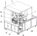
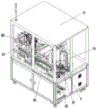
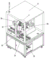
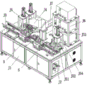
Fig. 1 is a schematic structural diagram of an embodiment of the present invention. Fig. 2 is a schematic structural diagram of a front end cover feeding device according to an embodiment of the present invention. Fig. 3 is a schematic view of the rear view of fig. 2. Fig. 4 is a schematic structural diagram of a lamp panel locking device according to an embodiment of the invention. Fig. 5 is a schematic structural view of a foam assembly device according to an embodiment of the present invention. Fig. 6 is a schematic structural diagram of a motherboard feeding device according to an embodiment of the present invention. Fig. 7 is a schematic structural diagram of a motherboard locking device according to an embodiment of the present invention. Fig. 8 is a schematic structural view of a front end cover locking device according to an embodiment of the present invention. Fig. 9 is a schematic structural diagram of a labeling device according to an embodiment of the invention. FIG. 10 is a schematic diagram of an air-testing device according to an embodiment of the invention. Fig. 11 is a schematic structural view of a decorative cover assembly device according to an embodiment of the present invention. Fig. 12 is a schematic structural diagram of an assembly fixture positioning device according to an embodiment of the invention. Fig. 13 is a schematic structural diagram of an assembly fixture lifting mechanism according to an embodiment of the present invention. Fig. 14 is an enlarged schematic view of the Q portion of fig. 11. Fig. 15 is an enlarged schematic view of the T portion of fig. 11. Fig. 16 is an enlarged schematic view of the P portion of fig. 9. Fig. 17 is an enlarged schematic view of the portion O of fig. 8. Fig. 18 is an enlarged schematic view of the portion N of fig. 5. Fig. 19 is a partially enlarged schematic view of the structure of fig. 4. Fig. 20 is an enlarged schematic view of the portion M of fig. 2.
Detailed Description
The present invention will be described in further detail by way of examples with reference to the accompanying drawings, which are illustrative of the present invention and not limited to the following examples.
Referring to fig. 1 to 20, an embodiment of the present invention includes first to eleventh stations, which are sequentially disposed.
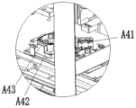
1. And the front end cover feeding device A is arranged on the first station. Front end cap loading attachment A includes first frame A1, first lower floor transfer chain A2, first upper transfer chain A3, front end cap location frock A4, front end cap material loading robot A5 and assembly frock hoist mechanism R.
The first lower layer conveying line A2 and the first upper layer conveying line A3 are arranged on the first frame A1, and the first lower layer conveying line A2 is located below the first upper layer conveying line A3. The front end cover loading robot A5 is mounted on the first frame A1. The front end cover positioning tool A4 is mounted on the first frame A1 and comprises a front end cover positioning cylinder A41, a front end cover positioning seat A42 and a front end cover positioning backing A43. The front end cap positioning cylinder a41 and the front end cap positioning seat a42 are mounted on the first frame A1. The front end cover positioning leaning hill A43 is fixed on the front end cover positioning seat A42 and is opposite to the piston of the front end cover positioning cylinder A41. The front end cover feeding device A is provided with a fitting feeding device L. The accessory loading attachment L includes feeding conveyer belt mechanism L1, feeding lift straight line module L2, feeding lifter plate L3, ejection of compact conveyer belt mechanism L4, ejection of compact lift straight line module L5, ejection of compact lifter plate L6, shifts straight line module L7 and snatchs mechanism L8. The feeding conveyer belt mechanism L1, the feeding lifting linear module L2, the discharging conveyer belt mechanism L4, the discharging lifting linear module L5 and the transferring linear module L7 are all installed on the first frame A1. The feeding conveyor belt mechanism L1 is horizontally arranged and is positioned beside the feeding lifting linear module L2. The feeding lifting linear module L2 is vertically arranged. The feeding lifting plate L3 is arranged on the feeding lifting linear module L2, and the feeding lifting plate L3 is matched with the feeding conveying belt mechanism L1. The discharging conveying belt mechanism L4 is horizontally arranged and is positioned beside the discharging lifting linear module L5. The discharging lifting linear module L5 is vertically arranged. The ejection of compact lifter plate L6 is installed on ejection of compact lift straight line module L5, and ejection of compact lifter plate L6 cooperates with ejection of compact conveyer belt mechanism L4.
The grabbing mechanism L8 is arranged on the transfer linear module L7, and the grabbing mechanism L8 comprises a grabbing lifting cylinder mounting plate L81, a grabbing lifting cylinder L82, a grabbing suction head mounting plate L83 and a grabbing suction head L84. The grabbing lifting cylinder mounting plate L81 is mounted on the transfer linear module L7. The grabbing lifting cylinder L82 is arranged on the grabbing lifting cylinder mounting plate L81, and the grabbing lifting cylinder L82 is vertically arranged. The grip tip mounting plate L83 is mounted on the piston of the grip lifting cylinder L82. The grabbing suction head L84 is mounted on the grabbing suction head mounting plate L83, and the grabbing suction head L84 is vertically arranged. The assembly fixture lifting mechanism R comprises a lifter R1, an outer baffle mechanism R2, an inner baffle mechanism R3 and a lifting plate R4. The lifter R1 is mounted on the first frame A1. The lifter plate R4 is mounted on the lifter R1. The lifting plate R4 is provided with a pulley R5. The lifter plate R4 cooperates with the first lower-layer conveyor line A2 and the first upper-layer conveyor line A3. The inner barrier mechanism R3 includes an inner fixing plate R31 and an inner barrier R32. The inner fixing plate R31 is fixed to the lifting plate R4. The inner baffle R32 is arranged on the inner fixing plate R31, a waist-shaped hole is formed in the inner baffle R32, and the inner baffle R32 is arranged on the inner fixing plate R31 through a mounting bolt in the waist-shaped hole, so that the position of the inner baffle R32 can be adjusted, and the blocking position can be adjusted. The outer barrier mechanism R2 includes an outer fixing plate R21, an outer barrier R22, and a spring R23. The outer fixing plate R21 is mounted on the first frame A1. The outer barrier R22 is elastically mounted on the outer fixing plate R21 by a spring R23. The lifting plate R4 is engaged with the outer barrier R22.
(1) The lifter R1 drives the lifting plate R4 to descend to the low position, and the lifting plate R4 presses down the outer baffle plate R22; the first lower layer conveying line A2 conveys the empty assembly fixture U into the lifting plate R4, and the inner baffle plate R32 blocks the assembly fixture U and positions the assembly fixture U; the lifter R1 drives the lifting plate R4 to rise to a high position, and the assembly fixture U is conveyed into a working position by the first upper conveying line A3; after the lifting plate R4 ascends, the outer baffle R22 returns under the action of the spring R23 to block the assembly fixture U behind the first lower layer conveying line A2; (2) Placing a plurality of front end covers into a material tray, and then placing the material tray on a feeding conveyer belt mechanism L1; after the feeding conveyor belt mechanism L1 conveys the material tray inwards to a proper position, the material tray is just above the feeding lifting plate L3 positioned at a low position; (3) The feeding lifting linear module L2 drives the feeding lifting plate L3 to lift, and the feeding lifting plate L3 drives the material tray to lift; after the feeding lifting plate L3 rises to a high position, the front end cover feeding robot A5 grabs the front end cover from the material tray, the front end cover is placed on the front end cover positioning seat A42, the front end cover positioning cylinder A41 acts, the front end cover is pushed onto the front end cover positioning backing A43 by the piston of the front end cover positioning cylinder A41, and the front end cover positioning backing A43 is fixed, so that the front end cover is positioned; the front end cover feeding robot A5 grabs the positioned front end cover and puts the front end cover into an assembly fixture U on the first upper layer conveying line A3; (4) After the front end cover in the material tray on the feeding lifting plate L3 is completely gripped by the front end cover feeding robot A5, the transfer linear module L7 moves to grip the lifting cylinder mounting plate L81, the gripping mechanism L8 moves to the position above the empty material tray, the gripping lifting cylinder L82 acts, the gripping suction head mounting plate L83 descends, the gripping suction head L84 sucks the material tray, then the gripping suction head mounting plate L83 ascends, the gripping suction head L84 lifts the material tray from the feeding lifting plate L3, and the feeding lifting plate L3 is driven to return to the low position by the feeding lifting linear module L2; the linear transfer module L7 moves the grabbing lifting cylinder mounting plate L81 again, the grabbing mechanism L8 is moved to the position above the discharging lifting plate L6 at a high position, the grabbing lifting cylinder L82 moves again, the grabbing suction head mounting plate L83 descends, the grabbing suction head L84 loosens a material disc, and the material disc is located on the discharging lifting plate L6; (5) The discharging lifting linear module L5 drives the discharging lifting plate L6 to descend, and the discharging lifting plate L6 drives the material tray to descend; after the discharging lifting plate L6 descends to the low position, the discharging conveying belt mechanism L4 conveys the material tray outwards, the empty material tray is taken away by a worker, and the discharging lifting linear module L5 drives the discharging lifting plate L6 to ascend to the high position again.
2. And a manual lamp panel feeding device B is arranged on the second station. The manual lamp panel feeding device B comprises a second frame B1, a second upper layer conveying line B2 and a second lower layer conveying line.
The second upper conveyor line B2 and the second lower conveyor line are mounted on the second frame B1. The second lower floor transfer chain is located the second upper strata transfer chain below. The second upper layer conveying line B2 is connected with the first upper layer conveying line A3, and the second lower layer conveying line is connected with the first lower layer conveying line A2. The first upper conveying line A3 conveys the assembly fixture U with the front end cover to the second upper conveying line B2, the second upper conveying line B2 conveys the assembly fixture U to a working position, a worker places the lamp panel into the front end cover, then the fixture cover is clamped on the assembly fixture U, and the fixture cover presses the lamp panel, so that the lamp panel and the front end cover are pressed together.
3. And a lamp panel locking device C is arranged on the third station. The lamp panel locking and attaching device C comprises a third frame C1, a third lower layer conveying line C2, a third upper layer conveying line C3, a lamp panel locking and attaching robot C4, a lamp panel screw feeding mechanism C5, a lamp panel screw locking machine C6, a tool cover pulling mechanism C7 and a tool cover backflow plate C8.
The third lower layer conveying line C2 and the third upper layer conveying line C3 are installed on the third frame C1, and the third lower layer conveying line C2 is located below the third upper layer conveying line C3. The third lower layer conveying line C2 is connected with the second lower layer conveying line, and the third upper layer conveying line C3 is connected with the second upper layer conveying line B2. The lamp panel locking robot C4 is installed on the third frame C1, and the lamp panel locking robot C4 is a linear robot. The lamp panel locking robot C4 is provided with a lamp panel screw locking machine C6 and a tool cover pulling mechanism C7. The tool cover pulling mechanism C7 comprises a tool cover pulling cylinder mounting plate C71, a tool cover pulling cylinder C72 and a tool cover pulling chuck C73, wherein the tool cover pulling cylinder mounting plate C71 is mounted on the lamp panel locking robot C4, the tool cover pulling cylinder C72 is mounted on the tool cover pulling cylinder mounting plate C71, and the tool cover pulling chuck C73 is mounted on the tool cover pulling cylinder C72. The lamp panel screw feeding mechanism C5 is arranged on the third frame C1. The lamp panel screw feeding mechanism C5 is used for feeding screws and adopts a vibration feeding mode. The tooling cover reflux plate C8 is installed on the third frame C1 and is obliquely arranged.
(1) The second upper layer conveying line B2 conveys the assembly fixture U to the third upper layer conveying line C3, and the third upper layer conveying line C3 conveys the assembly fixture U to a working position; (2) The lamp panel locking robot C4 drives the lamp panel locking screw machine C6 to move, and the lamp panel locking screw machine C6 fixes the lamp panel in the assembly fixture U and the front end cover together through screws; (3) Then the lamp panel locking robot C4 drives the tool cover pulling mechanism C7 to move to a working position, the tool cover pulling cylinder C72 drives the tool cover pulling chuck C73 to clamp the tool cover, the lamp panel locking robot C4 drives the tool cover pulling mechanism C7 to move, and the tool cover pulling chuck C73 pulls the tool cover out of the assembly tool U, so that the lamp panel locking process is completed; (4) The lamp panel locking robot C4 drives the tool cover pulling mechanism C7 to move to the position above the tool cover backflow plate C8, the tool cover pulling clamping head C73 is loosened, the tool cover falls to the tool cover backflow plate C8, and the tool cover slides into the collecting basket along the tool cover backflow plate C8.
4. And the fourth station is provided with a foam assembling device D. The foam assembly device D comprises a fourth frame D1, a foam feeding mechanism D2, a dust removing mechanism D3, a foam assembly robot D4, a foam clamp D5, a foam assembly platform D6, a fourth lower conveying line D7 and a fourth upper conveying line D8.
The fourth lower layer conveying line D7 and the fourth upper layer conveying line D8 are both installed on the fourth frame D1, and the fourth lower layer conveying line D7 is located below the fourth upper layer conveying line D8. The fourth lower layer conveying line D7 is connected to the third lower layer conveying line C2, and the fourth upper layer conveying line D8 is connected to the third upper layer conveying line C3. The foam feeding mechanism D2 is arranged on the fourth frame D1. The foam feeding mechanism D2 is used for feeding foam materials and adopts a vibration feeding mode. The foam assembling robot D4 is mounted on the fourth frame D1. The foam assembling robot D4 is a linear robot. The foam clamp D5 is mounted on the foam assembly robot D4. The foam clamp D5 comprises a foam clamp cylinder D51, a foam clamp cylinder mounting plate D52, a foam suction head D53 and a foam suction head mounting plate D54. The foam clamp cylinder mounting plate D52 is mounted on the foam assembly robot D4. The foam clamp cylinder D51 is arranged on the foam clamp cylinder mounting plate D52 and is vertically arranged downwards. The foam suction head mounting plate D54 is mounted on the piston of the foam suction head D53. The foam suction head D53 is arranged on the foam suction head mounting plate D54. The dust removing mechanism D3 is mounted on the fourth frame D1. The dust removing mechanism D3 is provided with an air hole D31, and the air hole D31 is connected with an air suction device. The foam assembly platform D6 comprises a foam upper jacking cylinder D61, a foam placing platform D62, a foam positioning plate D63 and a foam positioning plate transverse moving cylinder D64. The foam upper jacking cylinder D61 is arranged on the fourth frame D1 and is vertically upwards. The foam placing table D62 is arranged on a piston of the foam upper jacking cylinder D61. The foam positioning plate traversing cylinder D64 is mounted on the fourth frame D1 and is horizontally arranged. The foam positioning plate D63 is arranged on a piston of the foam positioning plate transverse moving cylinder D64, a notch is formed in the foam positioning plate D63, and the width of the notch is larger than or equal to the diameter of a lens on the main board; the foam positioning plate D63 is positioned above the foam placing table D62.
(1) The foam assembling robot D4 drives the foam clamp D5 to move to the foam feeding mechanism D2, and the foam suction head D53 of the foam clamp D5 sucks foam from the foam feeding mechanism D2; (2) The foam assembling robot D4 drives the foam clamp D5 to move to the dust removing mechanism D3, and the air holes D31 of the dust removing mechanism D3 absorb sundries such as dust on the foam 13; (3) The foam assembling robot D4 drives the foam clamp D5 to move to the foam assembling platform D6, the piston of the foam clamp cylinder D51 descends to place foam on the foam placing platform D62, and the foam suction head D53 loosens the foam; the foam assembling robot D4 drives the foam clamp D5 to leave the foam assembling platform D6; (4) The foam positioning plate traversing cylinder D64 drives the foam positioning plate D63 to horizontally move to the position right above the foam placing table D62; the robot of the latter station sets the main board with lens above the foam locating board D63, and the lens on the main board stretches into the notch; the piston of the foam upper pushing cylinder D61 drives the foam placing table D62 to ascend, the foam placing table D62 pushes foam upwards, and the foam is clamped into the lens to complete the foam assembling process; in the process, the foam positioning plate D63 plays a role in positioning the position of the foam on the lens, and the foam is the best mounting position of the foam when the foam positioning plate D63 contacts the bottom of the foam when the foam placing table D62 is pushed upwards.
5. And the fifth station is provided with a main board feeding device E. The main board feeding device E comprises a fifth frame E1, a fifth upper conveying line E2, a fifth lower conveying line E3, a vision device E4 and a main board feeding robot E5.
The fifth upper conveyor line E2 and the fifth lower conveyor line E3 are mounted on the fifth frame E1. The fifth lower conveyor line E3 is located below the fifth upper conveyor line E2. The fifth upper layer conveyor line E2 is connected to the fourth upper layer conveyor line D8, and the fifth lower layer conveyor line E3 is connected to the fourth lower layer conveyor line D7. The vision device E4 is mounted on the fifth frame E1. The main board feeding robot E5 is mounted on the fifth frame E1. The main board feeding device E is also provided with the accessory feeding device L. The accessory loading attachment L includes feeding conveyer belt mechanism L1, feeding lift straight line module L2, feeding lifter plate L3, ejection of compact conveyer belt mechanism L4, ejection of compact lift straight line module L5, ejection of compact lifter plate L6, shifts straight line module L7 and snatchs mechanism L8. The feeding conveyer belt mechanism L1, the feeding lifting linear module L2, the discharging conveyer belt mechanism L4, the discharging lifting linear module L5 and the transferring linear module L7 are all installed on the fifth frame E1. The feeding conveyor belt mechanism L1 is horizontally arranged and is positioned beside the feeding lifting linear module L2. The feeding lifting linear module L2 is vertically arranged. The feeding lifting plate L3 is arranged on the feeding lifting linear module L2, and the feeding lifting plate L3 is matched with the feeding conveying belt mechanism L1. The discharging conveying belt mechanism L4 is horizontally arranged and is positioned beside the discharging lifting linear module L5. The discharging lifting linear module L5 is vertically arranged. The ejection of compact lifter plate L6 is installed on ejection of compact lift straight line module L5, and ejection of compact lifter plate L6 cooperates with ejection of compact conveyer belt mechanism L4. The grabbing mechanism L8 is arranged on the transfer linear module L7, and the grabbing mechanism L8 comprises a grabbing lifting cylinder mounting plate L81, a grabbing lifting cylinder L82, a grabbing suction head mounting plate L83 and a grabbing suction head L84. The grabbing lifting cylinder mounting plate L81 is mounted on the transfer linear module L7. The grabbing lifting cylinder L82 is arranged on the grabbing lifting cylinder mounting plate L81, and the grabbing lifting cylinder L82 is vertically arranged. The grip tip mounting plate L83 is mounted on the piston of the grip lifting cylinder L82. The grabbing suction head L84 is mounted on the grabbing suction head mounting plate L83, and the grabbing suction head L84 is vertically arranged.
(1) The assembly fixture U on the third upper layer conveying line C3 after finishing the lamp panel locking process passes through the fourth upper layer conveying line D8 and then enters the fifth upper layer conveying line E2, and the assembly fixture U is conveyed to a working position by the fifth upper layer conveying line E2; (2) Placing a plurality of mainboards provided with lenses into a tray, and then placing the tray on a feeding conveyer belt mechanism L1; after the feeding conveyor belt mechanism L1 conveys the material tray inwards to a proper position, the material tray is just above the feeding lifting plate L3 positioned at a low position; (3) The feeding lifting linear module L2 drives the feeding lifting plate L3 to lift, and the feeding lifting plate L3 drives the material tray to lift; after the feeding lifting plate L3 is lifted to a high position, the main board feeding robot E5 grabs the main board from the material tray, and the main board is placed on the vision device E4 for positioning; (4) The main board feeding robot A5 is used for arranging the positioned main board above the foam positioning board D63 for foam assembly; after the foam assembly process is completed, the main board feeding robot A5 places the main board into a front end cover of an assembly fixture U positioned on a fifth upper layer conveying line E2, and the main board feeding process is completed; (5) After the main board in the tray on the feeding lifting plate L3 is completely gripped by the main board feeding robot A5, the transfer linear module L7 moves to grip the lifting cylinder mounting plate L81, the gripping mechanism L8 moves to the position above the empty tray, the gripping lifting cylinder L82 acts, the gripping suction head mounting plate L83 descends, the gripping suction head L84 sucks the tray, then the gripping suction head mounting plate L83 ascends, the gripping suction head L84 lifts the tray from the feeding lifting plate L3, and the feeding lifting plate L3 is driven to return to the low position by the feeding lifting linear module L2; the linear transfer module L7 moves the grabbing lifting cylinder mounting plate L81 again, the grabbing mechanism L8 is moved to the position above the discharging lifting plate L6 at a high position, the grabbing lifting cylinder L82 moves again, the grabbing suction head mounting plate L83 descends, the grabbing suction head L84 loosens a material disc, and the material disc is located on the discharging lifting plate L6; (6) The discharging lifting linear module L5 drives the discharging lifting plate L6 to descend, and the discharging lifting plate L6 drives the material tray to descend; after the discharging lifting plate L6 descends to the low position, the discharging conveying belt mechanism L4 conveys the material tray outwards, the empty material tray is taken away by a worker, and the discharging lifting linear module L5 drives the discharging lifting plate L6 to ascend to the high position again.
6. And the sixth station is provided with a main board locking device F. The main board locking device F comprises a sixth frame F1, a sixth lower layer conveying line F2, a sixth upper layer conveying line F3, a main board locking robot F4, a main board screw feeding mechanism F5 and a main board screw locking machine F6.
The sixth lower layer conveying line F2 and the sixth upper layer conveying line F3 are installed on the sixth frame F1, and the sixth lower layer conveying line F2 is located below the sixth upper layer conveying line F3. The sixth lower-layer conveying line F2 is connected to the fifth lower-layer conveying line E3, and the sixth upper-layer conveying line F3 is connected to the fifth upper-layer conveying line E2. The motherboard locking robot F4 is mounted on the sixth frame F1, and the motherboard locking robot F4 is a linear robot. The main board locking robot F4 is provided with a main board screw locking machine F6. The main board screw feeding mechanism F5 is mounted on the sixth frame F1. The main board screw feeding mechanism F5 is used for feeding screws and adopts a vibration feeding mode.
(1) The fifth upper layer conveying line E2 conveys the assembly fixture U which completes the main board feeding process to a sixth upper layer conveying line F3; the sixth upper layer conveying line F3 conveys the assembly fixture U to a working position; (2) And the main board locking robot F4 drives the main board locking screw machine F6 to move to a working position, and the main board locking screw machine F6 fixes the main board in the assembly tool U and the front end cover together by screws, so that a main board locking process is completed.
7. And a manual wire plugging device G is arranged on the seventh station. The manual wire inserting device G comprises a seventh frame G1, a seventh upper conveying line G2 and a seventh lower conveying line. The seventh upper conveyor line G2 and the seventh lower conveyor line are mounted on the seventh frame G1. The seventh lower conveying line is located below the seventh upper conveying line. The seventh upper layer conveying line G2 is connected to the sixth upper layer conveying line F3, and the seventh lower layer conveying line is connected to the sixth lower layer conveying line F2. The sixth upper layer conveying line F3 conveys the assembly fixture U to the seventh upper layer conveying line G2, a worker places the shell of the camera into the assembly fixture U, then inserts each wire of the camera into a corresponding socket, and then places the front end cover on the shell to complete the manual wire plugging process.
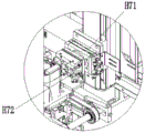
8. The eighth station is provided with a front end cover locking device H. The front end cover locking and attaching device H comprises an eighth frame H1, an eighth lower layer conveying line H2, an eighth upper layer conveying line H3, a front end cover locking and attaching robot H4, an eighth station overturning robot H5, a front end cover screw locking machine H6, an eighth station overturning mechanism H7 and a pressing mechanism.
The eighth lower layer conveying line H2 and the eighth upper layer conveying line H3 are installed on the eighth frame H1, and the eighth lower layer conveying line H2 is located below the eighth upper layer conveying line H3. The eighth lower layer conveying line H2 is connected to the seventh lower layer conveying line, and the eighth upper layer conveying line H3 is connected to the seventh upper layer conveying line G2. The front end cover locking robot H4 is arranged on the eighth frame H1, and the front end cover locking screw machine H6 is arranged on the front end cover locking robot H4. The eighth station turning robot H5 is mounted on the eighth frame H1, and the eighth station turning mechanism H7 is mounted on the eighth station turning robot H5. The eighth station turning mechanism H7 comprises an eighth station rotary cylinder H71 and an eighth station pneumatic clamping jaw H72. The eighth station rotating cylinder H71 is mounted on the eighth station turning robot H5. The eighth station pneumatic clamping jaw H72 is mounted on the eighth station rotary cylinder H71. The eighth station turning robot H5 and the front end cover locking robot H4 are disposed back and forth along the conveying direction of the eighth upper conveying line H3. The pressing mechanism is installed at the eighth frame H1 and located beside the eighth upper conveyor line H3. The compressing mechanism comprises a compressing cylinder and a compressing plate, and a piston of the compressing cylinder is connected with the compressing plate.
(1) The seventh upper layer conveying line G2 conveys the assembly fixture U which completes the manual wire inserting process to the eighth upper layer conveying line H3, and the eighth upper layer conveying line H3 conveys the assembly fixture U to the first working position; (2) The compressing cylinder drives the compressing plate to press down and tightly compress the front end cover, the front end cover locking robot H4 drives the front end cover screw locking machine H6 to move to a working position, and the front end cover screw locking machine H6 fixes the front end cover and the shell in the assembly tool U together through screws; (3) The eighth upper layer conveying line H3 continuously conveys the assembly fixture U to a second working position; the eighth station turning robot H5 drives the eighth station turning mechanism H7 to descend to a working position, the eighth station pneumatic clamping jaw H72 clamps the camera, the eighth station turning robot H5 drives the eighth station turning mechanism H7 to ascend to a certain height, and the eighth station rotating cylinder H71 drives the eighth station pneumatic clamping jaw H72 to rotate, so that the tail part of the camera faces upwards (namely, the front end cover is arranged below and the shell is arranged above); the eighth station overturning robot H5 drives the eighth station overturning mechanism H7 to descend, and after the camera is put into the assembly tool U again, the eighth station pneumatic clamping jaw H72 is loosened, so that the front end cover locking process is completed.
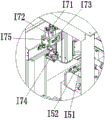
9. And the ninth station is provided with a labeling device I. The labeling device I comprises a ninth frame I1, a ninth lower layer conveying line I2, a ninth upper layer conveying line I3, a label conveying mechanism I4, a labeling separating mechanism I5, a labeling robot I6 and a label clamp I7.
The ninth lower layer conveying line I2 and the ninth upper layer conveying line I3 are mounted on the ninth frame I1, and the ninth lower layer conveying line I2 is located below the ninth upper layer conveying line I3. The ninth lower layer conveying line I2 is connected with the eighth lower layer conveying line H2, and the ninth upper layer conveying line I3 is connected with the eighth upper layer conveying line H3. The label conveying mechanism I4 is mounted on the ninth frame I1. The label separating mechanism I5 is engaged with the label conveying mechanism I4. The labeling and separating mechanism I5 includes a separating table I51 and a separating block I52. The separation block I52 is fixed at on the separating table I51, the number of the separation blocks I52 is two, and the separation blocks I are arranged left and right. The labeler robot I6 is mounted on the ninth frame I1. The label holder I7 is mounted on the labelling robot I6. The label clamp I7 comprises a label clamp cylinder I71, a swinging rod I72, a label clamp mounting plate I73, a label suction head I74 and a limit bolt I75. The label clamp mounting plate I73 is mounted on the labeler robot I6. The tag jig cylinder I71 is mounted on the tag jig mounting plate I73. The middle part of the swinging rod I72 is hinged on the label clamp mounting plate I73, and the head part is connected with a piston of the label clamp cylinder I71. A label suction head I74 is mounted to the bottom of the swing lever I72. The limit bolt I75 is mounted on the tag clamp mounting plate I73 and is matched with the swinging rod I72.
(1) The eighth upper layer conveying line H3 conveys the assembly fixture U after the front end cover locking process is completed to a ninth upper layer conveying line I3, and the ninth upper layer conveying line I3 conveys the assembly fixture U to a working position; (2) The label tape on the label conveying mechanism I4 is lapped on a separating block I52 of the labeling separating mechanism I5 and then returns to the label conveying mechanism I4; (3) The label clamp cylinder I71 acts, and the piston of the label clamp cylinder I drives the swing rod I72 to rotate, so that the swing rod I72 is in a vertical position, and the label suction head I74 is vertical at the moment; (4) The labeling robot I6 drives the label clamp I7 to move to the labeling separation mechanism I5, the labeling robot I6 drives the label suction head I74 of the label clamp I7 to press on a label belt between two separation blocks I52, and as the separation blocks I52 and the separation table I51 have a height difference, labels on the label belt are in a suspended state, and the labels are pressed out of the label belt by the label suction head I74 and sucked by the label suction head I74; (5) The labeling robot I6 drives the label clamp I7 to move to a camera on the assembly tool U, the label clamp cylinder I71 acts, and the piston of the label clamp cylinder I pushes the swinging rod I72 to rotate, so that the swinging rod I72 is in an inclined position, and the label suction head I74 is inclined at the moment because the place where the camera is attached with a label (namely the tail of the camera) is also inclined; (6) And the labeling robot I6 drives the label suction head I74 of the label clamp I7 to label the label at the place where the camera is used for labeling, so that the labeling process is completed.
10. And the tenth station is provided with an air measuring device J. The air testing device J comprises a tenth frame J1, a tenth lower layer conveying line J2, a tenth upper layer conveying line J3, an air testing robot J4, a testing tool J5, an air tightness detection mechanism J6 and a defective product outflow conveying line J7.
The tenth lower layer conveying line J2 and the tenth upper layer conveying line J3 are installed on the tenth frame J1, and the tenth lower layer conveying line J2 is located below the tenth upper layer conveying line J3. The tenth lower-layer conveying line J2 is connected to the ninth lower-layer conveying line I2, and the tenth upper-layer conveying line J3 is connected to the ninth upper-layer conveying line I3. The gas detection robot J4 is mounted on the tenth frame J1. The test tool J5 and the airtightness detection mechanism J6 are both installed on the tenth frame J1. The test tool J5 is connected with the air tightness detection mechanism J6. The test fixture J5 comprises a test bench J51, a test cover J52, a test cover cylinder J53 and a test frame J54. The test rack J54 is mounted on the tenth frame J1. Test bench J51 is installed on test frame J54, is provided with the trachea on the test bench J51. The test cover cylinder J53 is mounted on the test rack J54. Test cup J52 is mounted on the piston of test cup cylinder J53 and mates with test stand J51. The defective product outflow conveyor line J7 is mounted on the tenth frame J1.
(1) The ninth upper layer conveying line I3 conveys the assembly fixture U to the tenth upper layer conveying line J3, and the tenth upper layer conveying line J3 conveys the assembly fixture U to a working position; (2) The gas detection robot J4 places a camera on the assembly tool U on the test bench J51 through a clamp; the test cover cylinder J53 acts to estimate the test cover J52 downwards, the test cover J52 is covered on the test table J51, and the camera is positioned in a sealed space between the test cover J52 and the test table J51; (3) The air is ventilated into the sealed space through an air pipe on the test bench J51, and the air tightness detection mechanism J6 detects the air tightness of the camera; (4) After the detection is finished, the gas detection robot J4 places the qualified camera on the assembly tool U again through the clamp to finish the gas detection process; and the unqualified cameras are placed in a defective product outflow conveying line J7 for outflow.
11. The eleventh station is provided with a decorative cover assembly device K. The decorative cover assembly device K comprises an eleventh frame K1, an eleventh lower layer conveying line, an eleventh upper layer conveying line K3, a decorative cover press attachment robot K4, an eleventh station overturning robot K5, a decorative cover clamp K6, an eleventh station overturning mechanism K7, a decorative cover positioning tool K8, a product outflow conveying line K2 and an assembly tool recycling mechanism K9.
The eleventh lower layer conveying line and the eleventh upper layer conveying line K3 are installed on the eleventh frame K1, and the tenth lower layer conveying line is located below the eleventh upper layer conveying line K3. The tenth lower layer transfer chain is connected with tenth lower floor transfer chain J2, and eleventh upper layer transfer chain K3 is connected with tenth upper layer transfer chain J3. The decorative cover attaching robot K4 is mounted on the eleventh frame K1, and the decorative cover clamp K6 is mounted on the decorative cover attaching robot K4. The decorative cover clamp K6 is provided with a camera pneumatic clamping jaw and a decorative cover suction head. The eleventh station turning robot K5 is mounted on the eleventh frame K1, and the eleventh station turning mechanism K7 is mounted on the eleventh station turning robot K5. The eleventh station turnover mechanism K7 comprises an eleventh station rotary cylinder K71 and an eleventh station pneumatic clamping jaw K72. The eleventh station rotating cylinder K71 is mounted on the eleventh station turning robot K5. The eleventh station pneumatic clamping jaw K72 is mounted on the eleventh station rotary cylinder K71. The decorative cover press robot K4 and the eleventh station turning robot K5 are disposed back and forth along the conveying direction of the eleventh upper layer conveying line K3. The decorative cover positioning tool K8 is arranged on the eleventh frame K1 and comprises a decorative cover positioning cylinder K81, a decorative cover positioning seat K82 and a decorative cover positioning backing K83. The decorative cover positioning cylinder K81 and the decorative cover positioning seat K82 are mounted on the eleventh frame K1. The decorative cover positioning backing K83 is fixed on the decorative cover positioning seat K82 and is opposite to the piston of the decorative cover positioning cylinder K81. The fitting loading device L is also mounted in the decorative cover assembling device K. The accessory loading attachment L includes feeding conveyer belt mechanism L1, feeding lift straight line module L2, feeding lifter plate L3, ejection of compact conveyer belt mechanism L4, ejection of compact lift straight line module L5, ejection of compact lifter plate L6, shifts straight line module L7 and snatchs mechanism L8. The feeding conveyer belt mechanism L1, the feeding lifting linear module L2, the discharging conveyer belt mechanism L4, the discharging lifting linear module L5 and the transferring linear module L7 are all installed on the eleventh frame K1. The feeding conveyor belt mechanism L1 is horizontally arranged and is positioned beside the feeding lifting linear module L2. The feeding lifting linear module L2 is vertically arranged. The feeding lifting plate L3 is arranged on the feeding lifting linear module L2, and the feeding lifting plate L3 is matched with the feeding conveying belt mechanism L1. The discharging conveying belt mechanism L4 is horizontally arranged and is positioned beside the discharging lifting linear module L5. The discharging lifting linear module L5 is vertically arranged. The ejection of compact lifter plate L6 is installed on ejection of compact lift straight line module L5, and ejection of compact lifter plate L6 cooperates with ejection of compact conveyer belt mechanism L4. The grabbing mechanism L8 is arranged on the transfer linear module L7, and the grabbing mechanism L8 comprises a grabbing lifting cylinder mounting plate L81, a grabbing lifting cylinder L82, a grabbing suction head mounting plate L83 and a grabbing suction head L84. The grabbing lifting cylinder mounting plate L81 is mounted on the transfer linear module L7. The grabbing lifting cylinder L82 is arranged on the grabbing lifting cylinder mounting plate L81, and the grabbing lifting cylinder L82 is vertically arranged. The grip tip mounting plate L83 is mounted on the piston of the grip lifting cylinder L82. The grabbing suction head L84 is mounted on the grabbing suction head mounting plate L83, and the grabbing suction head L84 is vertically arranged. The assembly fixture recycling mechanism K9 comprises a recycling lifter and a recycling lifting plate. The recovery lifter is mounted on the eleventh frame K1. The recovery lifting plate is arranged on the recovery lifter. The recovery lifting plate is matched with a tenth lower layer conveying line and an eleventh upper layer conveying line K3.
(1) The tenth upper layer conveying line J3 conveys the assembling tool U which completes the gas measurement procedure to an eleventh upper layer conveying line K3, and the eleventh upper layer conveying line K3 conveys the assembling tool U to a first working position; (2) The eleventh station turnover robot K5 drives the eleventh station turnover mechanism K7 to descend to a working position, the eleventh station pneumatic clamping jaw K72 clamps the camera, the eleventh station turnover robot K5 drives the eleventh station turnover mechanism K7 to ascend to a certain height, and the eleventh station rotating cylinder K71 drives the eleventh station pneumatic clamping jaw K72 to rotate so that the head of the camera faces upwards (namely, the front end cover is arranged above and the shell is arranged below); the eleventh station turnover robot K5 drives the eleventh station turnover mechanism K7 to descend, after the camera is put into the assembly fixture U again, the eleventh station pneumatic clamping jaw K72 is loosened, and the eleventh upper conveying line K3 conveys the assembly fixture U forwards to a second working position; (3) Placing each decorative cover into a tray, and then placing the tray on the feeding conveyor mechanism L1; after the feeding conveyor belt mechanism L1 conveys the material tray inwards to a proper position, the material tray is just above the feeding lifting plate L3 positioned at a low position; the feeding lifting linear module L2 drives the feeding lifting plate L3 to lift, and the feeding lifting plate L3 drives the material tray to lift; (4) After the feeding lifting plate L3 is lifted to a high position, the decorative cover pressing robot K4 sucks the decorative cover from the material tray through the decorative cover suction head in the decorative cover clamp K6, the decorative cover is placed on the decorative cover positioning seat K82, the decorative cover positioning cylinder K81 acts, the piston pushes the decorative cover to the decorative cover positioning backing K83, and the position of the decorative cover positioning backing K83 is fixed, so that the decorative cover is positioned; (5) The decoration cover pressing robot K4 grabs the positioned decoration cover, presses the decoration cover on the front end cover in the assembly tool U, and fixes the decoration cover and the front end cover together; then the pneumatic clamping jaw of the camera in the decorative cover clamp K6 clamps the camera, the camera is put on a product outflow conveying line K2 for output, and the assembly production of the whole camera is completed; the empty assembly fixture U is conveyed into the upper recovery lifting plate by the eleventh upper conveying line K3, the recovery lifting plate is driven by the recovery lifting machine to descend to the lower position, the assembly fixture U for recovering the lifting plate is conveyed away by the tenth lower conveying line and sequentially passes through the tenth to second lower conveying lines and then enters the first lower conveying line A2, and recycling is achieved; (6) After the decorative cover in the material tray on the feeding lifting plate L3 is completely grabbed by the decorative cover pressing robot K4, the transfer linear module L7 moves to grab the lifting cylinder mounting plate L81, the grabbing mechanism L8 is moved to the position above the empty material tray, the grabbing lifting cylinder L82 acts, the grabbing suction head mounting plate L83 descends, the grabbing suction head L84 sucks the material tray, then the grabbing suction head mounting plate L83 ascends, the grabbing suction head L84 lifts the material tray from the feeding lifting plate L3, and the feeding lifting plate L3 is driven to return to the low position by the feeding lifting linear module L2; the linear transfer module L7 moves the grabbing lifting cylinder mounting plate L81 again, the grabbing mechanism L8 is moved to the position above the discharging lifting plate L6 at a high position, the grabbing lifting cylinder L82 moves again, the grabbing suction head mounting plate L83 descends, the grabbing suction head L84 loosens a material disc, and the material disc is located on the discharging lifting plate L6; (5) The discharging lifting linear module L5 drives the discharging lifting plate L6 to descend, and the discharging lifting plate L6 drives the material tray to descend; after the discharging lifting plate L6 descends to the low position, the discharging conveying belt mechanism L4 conveys the material tray outwards, the empty material tray is taken away by a worker, and the discharging lifting linear module L5 drives the discharging lifting plate L6 to ascend to the high position again.
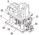
12. The front end cover feeding device A, the lamp panel locking device C, the main board feeding device E, the main board locking device F, the front end cover locking device H, the labeling device I, the gas detection device J and the decoration cover assembling device K are all provided with the assembling tool positioning device S. The assembly fixture positioning device S comprises a positioning block S1, a positioning block lifting cylinder S2, a jacking plate S3, a jacking cylinder S4, a jacking guide column S5, a bottom plate S6 and a sensor. The lifting plate S3 is installed on the bottom plate S6 in a lifting manner by the lifting guide post S5. The jacking cylinder S4 is mounted on the bottom plate S6, and its piston is connected to the jacking plate S3. The positioning block lifting cylinder S2 is arranged on the bottom plate S6, and a piston of the positioning block lifting cylinder S2 is connected with the positioning block S1. The assembly fixture U is detected by a sensor to reach each station, and a piston of the positioning block lifting cylinder S2 drives the positioning block S1 to move upwards to block the assembly fixture U; the piston of the jacking cylinder S4 drives the jacking plate S3 to move upwards to jack up the assembly fixture U, so that the assembly fixture U is separated from the upper conveying line. After each procedure is completed, the piston of the positioning block lifting cylinder S2 drives the positioning block S1 to move downwards, the piston of the jacking cylinder S4 drives the jacking plate S3 to move downwards, and the assembly fixture U is conveyed away by the upper conveying line.
Claims (8)
1. The utility model provides a camera assembly line which characterized in that: the device comprises a first station, a second station, a third station, a fourth station and a fifth station, wherein the first station is sequentially arranged from the first station to the eleventh station;
The front end cover feeding device is arranged on the first station; the front end cover feeding device comprises a first frame, a first lower layer conveying line, a first upper layer conveying line and a front end cover feeding robot; the first lower layer conveying line and the first upper layer conveying line are arranged on the first frame; the front end cover feeding robot is arranged on the first frame; the front end cover feeding device is internally provided with a fitting feeding device;
a manual lamp panel feeding device is arranged on the second station; the manual lamp panel feeding device comprises a second frame, a second upper layer conveying line and a second lower layer conveying line; the second upper layer conveying line and the second lower layer conveying line are arranged on the second frame, the second upper layer conveying line is connected with the first upper layer conveying line, and the second lower layer conveying line is connected with the first lower layer conveying line;
the third station is provided with a lamp panel locking device; the lamp panel locking device comprises a third frame, a third lower layer conveying line, a third upper layer conveying line, a lamp panel locking robot and a lamp panel screw locking machine; the third lower layer conveying line and the third upper layer conveying line are arranged on the third frame, the third lower layer conveying line is connected with the second lower layer conveying line, and the third upper layer conveying line is connected with the second upper layer conveying line; the lamp panel locking robot is arranged on the third frame, and a lamp panel screw locking machine is arranged on the lamp panel locking robot;
A foam assembly device is arranged on the fourth station; the foam assembly device comprises a fourth frame, a dust removing mechanism, a foam assembly robot, a foam clamp, a foam assembly platform, a fourth lower layer conveying line and a fourth upper layer conveying line; the fourth lower layer conveying line and the fourth upper layer conveying line are both arranged on the fourth frame, the fourth lower layer conveying line is connected with the third lower layer conveying line, and the fourth upper layer conveying line is connected with the third upper layer conveying line; the foam assembling robot is arranged on the fourth frame; the foam clamp is arranged on the foam assembly robot; the dust removing mechanism is arranged on the fourth frame; the foam assembly platform comprises a foam upper-jacking cylinder, a foam placing table, a foam positioning plate and a foam positioning plate transverse-moving cylinder; the foam upper jacking cylinder is arranged on the fourth frame and is vertically upwards arranged; the foam placing table is arranged on a piston of a foam upper jacking cylinder; the foam positioning plate transversely-moving air cylinder is arranged on the fourth frame and is horizontally arranged; the foam positioning plate is arranged on a piston of the foam positioning plate transverse moving cylinder; the foam positioning plate is positioned above the foam placing table;
a main board feeding device is arranged on the fifth station; the main board feeding device comprises a fifth frame, a fifth upper layer conveying line, a fifth lower layer conveying line, a vision device and a main board feeding robot; the fifth upper layer conveying line and the fifth lower layer conveying line are arranged on the fifth frame, the fifth upper layer conveying line is connected with the fourth upper layer conveying line, and the fifth lower layer conveying line is connected with the fourth lower layer conveying line; the vision device is mounted on the fifth frame; the main board feeding robot is arranged on the fifth frame; the main board feeding device is also provided with the accessory feeding device;
The sixth station is provided with a main board locking device; the main board locking device comprises a sixth frame, a sixth lower layer conveying line, a sixth upper layer conveying line, a main board locking robot and a main board screw locking machine; the sixth lower layer conveying line and the sixth upper layer conveying line are arranged on the sixth frame, the sixth lower layer conveying line is connected with the fifth lower layer conveying line, and the sixth upper layer conveying line is connected with the fifth upper layer conveying line; the main board locking robot is arranged on the sixth frame, and a main board screw locking machine is arranged on the main board locking robot;
a seventh station is provided with a manual wire plugging device; the manual wire inserting device comprises a seventh frame, a seventh upper layer conveying line and a seventh lower layer conveying line; the seventh upper layer conveying line and the seventh lower layer conveying line are arranged on the seventh frame, the seventh upper layer conveying line is connected with the sixth upper layer conveying line, and the seventh lower layer conveying line is connected with the sixth lower layer conveying line;
the eighth station is provided with a front end cover locking device; the front end cover locking device comprises an eighth frame, an eighth lower layer conveying line, an eighth upper layer conveying line, a front end cover locking robot, an eighth station turning robot, a front end cover screw locking machine and an eighth station turning mechanism; the eighth lower layer conveying line and the eighth upper layer conveying line are arranged on the eighth frame, the eighth lower layer conveying line is connected with the seventh lower layer conveying line, and the eighth upper layer conveying line is connected with the seventh upper layer conveying line; the front end cover locking robot is arranged on the eighth frame, and the front end cover screw locking machine is arranged on the front end cover locking robot; the eighth station overturning robot is arranged on the eighth frame, and the eighth station overturning mechanism is arranged on the eighth station overturning robot;
A labeling device is arranged on the ninth station; the labeling device comprises a ninth frame, a ninth lower layer conveying line, a ninth upper layer conveying line, a label conveying mechanism, a labeling robot and a label clamp; the ninth lower layer conveying line and the ninth upper layer conveying line are arranged on the ninth frame, the ninth lower layer conveying line is connected with the eighth lower layer conveying line, and the ninth upper layer conveying line is connected with the eighth upper layer conveying line; the label conveying mechanism is arranged on the ninth frame; the labeler robot is arranged on the ninth frame; the label clamp is arranged on the labeler;
the tenth station is provided with an air measuring device; the air testing device comprises a tenth frame, a tenth lower layer conveying line, a tenth upper layer conveying line, an air testing robot, a testing tool and an air tightness detection mechanism; the tenth lower layer conveying line and the tenth upper layer conveying line are arranged on the tenth frame, the tenth lower layer conveying line is connected with the ninth lower layer conveying line, and the tenth upper layer conveying line is connected with the ninth upper layer conveying line; the air detection robot is arranged on the tenth frame; the test tool and the air tightness detection mechanism are both arranged on the tenth frame; the test tool is connected with the air tightness detection mechanism; the test fixture comprises a test table, a test cover cylinder and a test frame; the test rack is arranged on the tenth frame; the test bench is arranged on the test frame; the test cover cylinder is arranged on the test frame; the test cover is arranged on a piston of the test cover cylinder and is matched with the test bench;
The eleventh station is provided with a decorative cover assembly device; the decorative cover assembly device comprises an eleventh frame, a tenth lower layer conveying line, an eleventh upper layer conveying line, a decorative cover press attachment robot, an eleventh station overturning robot, a decorative cover clamp, an eleventh station overturning mechanism and a decorative cover positioning tool; the eleventh lower layer conveying line and the eleventh upper layer conveying line are arranged on the eleventh frame, the tenth lower layer conveying line is connected with the tenth lower layer conveying line, and the eleventh upper layer conveying line is connected with the tenth upper layer conveying line; the decoration cover pressing robot is arranged on the eleventh frame, and the decoration cover clamp is arranged on the decoration cover pressing robot; the eleventh station turnover robot is arranged on the eleventh frame, and the eleventh station turnover mechanism is arranged on the eleventh station turnover robot; the decorative cover positioning tool is arranged on the eleventh frame; the accessory feeding device is also arranged in the decorative cover assembly device;
the eighth station overturning mechanism comprises an eighth station rotating cylinder and an eighth station pneumatic clamping jaw; the eighth station rotating cylinder is arranged on the eighth station overturning robot; the eighth station pneumatic clamping jaw is arranged on the eighth station rotary cylinder;
The eleventh station turnover mechanism comprises an eleventh station rotary cylinder and an eleventh station pneumatic clamping jaw; the eleventh station rotating cylinder is arranged on the eleventh station overturning robot; the eleventh station pneumatic clamping jaw is arranged on the eleventh station rotary cylinder.
2. The camera assembly line of claim 1, wherein: the front end cover feeding device further comprises a front end cover positioning tool; the front end cover positioning tool is arranged on the first frame and comprises a front end cover positioning cylinder, a front end cover positioning seat and a front end cover positioning backer; the front end cover positioning cylinder and the front end cover positioning seat are arranged on the first frame; the front end cover positioning backing is fixed on the front end cover positioning seat and is opposite to the piston of the front end cover positioning cylinder.
3. The camera assembly line of claim 1, wherein: the accessory feeding device comprises a feeding conveying belt mechanism, a feeding lifting linear module, a feeding lifting plate, a discharging conveying belt mechanism, a discharging lifting linear module, a discharging lifting plate, a transferring linear module and a grabbing mechanism; the feeding conveyor belt mechanism is horizontally arranged and is positioned beside the feeding lifting linear module; the feeding lifting linear module is vertically arranged; the feeding lifting plate is arranged on the feeding lifting linear module and is matched with the feeding conveying belt mechanism; the discharging conveying belt mechanism is horizontally arranged and is positioned beside the discharging lifting linear module; the discharging lifting linear module is vertically arranged; the discharging lifting plate is arranged on the discharging lifting linear module and is matched with the discharging conveying belt mechanism; the grabbing mechanism is arranged on the transfer linear module and comprises a grabbing lifting cylinder mounting plate, a grabbing lifting cylinder, a grabbing suction head mounting plate and a grabbing suction head; mounting plate of grabbing lifting cylinder on the transfer line module; the grabbing lifting cylinder is arranged on the grabbing lifting cylinder mounting plate and is vertically arranged; the grabbing suction head mounting plate is arranged on a piston of the grabbing lifting cylinder; the grabbing suction head is arranged on the grabbing suction head mounting plate, and the grabbing suction head is vertically arranged.
4. The camera assembly line of claim 1, wherein: the front end cover feeding device further comprises an assembly tool lifting mechanism, wherein the assembly tool lifting mechanism comprises a lifter, an outer baffle mechanism, an inner baffle mechanism and a lifting plate; the lifter is arranged on the first frame; the lifting plate is arranged on the lifter; the lifting plate is matched with the first lower layer conveying line and the first upper layer conveying line; the inner baffle mechanism comprises an inner fixed plate and an inner baffle; the inner side fixing plate is fixed on the lifting plate; the inner baffle is arranged on the inner fixing plate; the outer baffle mechanism comprises an outer fixing plate, an outer baffle and a spring; the outer fixing plate is arranged on the first frame; the outer baffle is elastically arranged on the outer fixing plate through a spring; the lifting plate is matched with the outer baffle.
5. The camera assembly line of claim 1, wherein: the lamp panel locking device also comprises a tool cover pulling mechanism and a tool cover reflux plate; the tool cover pulling mechanism comprises a tool cover pulling cylinder mounting plate, a tool cover pulling cylinder and a tool cover pulling chuck, wherein the tool cover pulling cylinder mounting plate is mounted on the lamp panel locking robot; the tool cover reflux plate is installed on the third frame and is obliquely arranged.
6. The camera assembly line of claim 1, wherein: the foam clamp comprises a foam clamp cylinder, a foam clamp cylinder mounting plate, a foam suction head and a foam suction head mounting plate; the foam clamp cylinder mounting plate is mounted on the foam assembly robot; the foam clamp cylinder is arranged on the foam clamp cylinder mounting plate and is vertically arranged downwards; the foam suction head mounting plate is arranged on the piston of the foam suction head; the foam suction head is arranged on the foam suction head mounting plate.
7. The camera assembly line of claim 1, wherein: the labeling device also comprises a labeling separating mechanism which is matched with the label conveying mechanism; the labeling and separating mechanism comprises a separating table and a separating block; the separation block is fixed on the separation table; the number of the separation blocks is two, and the separation blocks are arranged left and right.
8. The camera assembly line of claim 1, wherein: the label clamp comprises a label clamp cylinder, a swinging rod, a label clamp mounting plate, a label suction head and a limit bolt; the label clamp mounting plate is arranged on the labeler; the label clamp cylinder is arranged on the label clamp mounting plate; the middle part of the swinging rod is hinged on the label clamp mounting plate, and the head part of the swinging rod is connected with the piston of the label clamp cylinder; the label suction head is arranged at the bottom of the swinging rod; the limit bolt is installed on the label clamp mounting plate and matched with the swinging rod.
Priority Applications (1)
| Application Number | Priority Date | Filing Date | Title |
|---|---|---|---|
| CN201810201994.1A CN108340157B (en) | 2018-03-12 | 2018-03-12 | Camera assembly production line |
Applications Claiming Priority (1)
| Application Number | Priority Date | Filing Date | Title |
|---|---|---|---|
| CN201810201994.1A CN108340157B (en) | 2018-03-12 | 2018-03-12 | Camera assembly production line |
Publications (2)
| Publication Number | Publication Date |
|---|---|
| CN108340157A CN108340157A (en) | 2018-07-31 |
| CN108340157B true CN108340157B (en) | 2023-07-07 |
Family
ID=62956477
Family Applications (1)
| Application Number | Title | Priority Date | Filing Date |
|---|---|---|---|
| CN201810201994.1A Active CN108340157B (en) | 2018-03-12 | 2018-03-12 | Camera assembly production line |
Country Status (1)
| Country | Link |
|---|---|
| CN (1) | CN108340157B (en) |
Families Citing this family (5)
| Publication number | Priority date | Publication date | Assignee | Title |
|---|---|---|---|---|
| CN108890289B (en) * | 2018-09-14 | 2022-07-22 | 广东莞信科技创新有限公司 | Automatic case and bag assembling machine |
| CN111332737A (en) * | 2020-03-06 | 2020-06-26 | 广东金弘达自动化科技股份有限公司 | Optical product front cover assembly feeding device |
| CN111332786A (en) * | 2020-03-06 | 2020-06-26 | 广东金弘达自动化科技股份有限公司 | Automatic assembly line of optical product |
| CN112809369A (en) * | 2020-12-31 | 2021-05-18 | 昆山富利瑞电子科技有限公司 | Automatic assembly line for electronic sphygmomanometer |
| CN112676835B (en) * | 2020-12-31 | 2022-08-26 | 宁波加凯汽车部件有限公司 | Assembly equipment for cooling liquid pot cover |
Family Cites Families (6)
| Publication number | Priority date | Publication date | Assignee | Title |
|---|---|---|---|---|
| US20100217437A1 (en) * | 2009-02-24 | 2010-08-26 | Branko Sarh | Autonomous robotic assembly system |
| CN103692210B (en) * | 2013-12-21 | 2016-08-17 | 周俊雄 | Actuator automatically assembles and detects line |
| CN104801968B (en) * | 2015-02-13 | 2017-08-22 | 杭州新松机器人自动化有限公司 | Automatic assembly system and its method based on security protection industry camera core component |
| CN105598707B (en) * | 2016-01-29 | 2018-06-08 | 东莞市旭特机器人股份有限公司 | The automatic assembly line of Radar Products |
| CN106938729A (en) * | 2017-04-21 | 2017-07-11 | 东莞智荣机械有限公司 | Intelligence dress patch machine and its attaching method |
| CN208262255U (en) * | 2018-03-12 | 2018-12-21 | 上海宝嵩机器人有限公司 | Video camera Assembling Production assembly line |
-
2018
- 2018-03-12 CN CN201810201994.1A patent/CN108340157B/en active Active
Also Published As
| Publication number | Publication date |
|---|---|
| CN108340157A (en) | 2018-07-31 |
Similar Documents
| Publication | Publication Date | Title |
|---|---|---|
| CN108340157B (en) | Camera assembly production line | |
| CN109987395B (en) | Automatic feeding device for mobile phone frame | |
| CN108326546B (en) | Camera assembly quality | |
| CN112792550A (en) | Magnet assembling machine and assembling method | |
| CN107364719A (en) | A kind of sheet glass feeding and conveying device | |
| CN211888000U (en) | Automatic measuring equipment for camera lens | |
| CN105314139B (en) | Automatic hanging machine of pullers | |
| CN113320987A (en) | Feeding equipment | |
| CN206163470U (en) | Automatic dress that pastes in thermal -insulated area of product is equipped | |
| CN209954139U (en) | Automatic assembling equipment | |
| CN208262255U (en) | Video camera Assembling Production assembly line | |
| CN117007519A (en) | Appearance detection equipment of semiconductor chip frame | |
| CN111760799A (en) | Glass bottle sorting device | |
| CN209119052U (en) | A kind of pressing module of the automatic gland equipment of chip | |
| CN111056312A (en) | Automatic wire feeding system used before automobile front windshield combining | |
| CN216709737U (en) | Automatic plug loading device | |
| CN209889840U (en) | Automatic feeding system used before combining coated automobile front windshield | |
| CN114043796B (en) | Full-automatic laminating machine | |
| CN209466189U (en) | A kind of inclined-plane magnet cartridge carrier device | |
| CN211401514U (en) | Tension detection device of two-for-one twister capsule tensioner | |
| CN113804622A (en) | Appearance detection equipment | |
| CN209104133U (en) | A kind of pick-up component of the automatic gland equipment of chip | |
| CN208262256U (en) | The trim of video camera Assembling Production assembly line assembles device | |
| CN209119050U (en) | A kind of chip jig stacker mechanism | |
| CN112027266A (en) | Intelligent labeling mechanism robot for PCB and labeling method |
Legal Events
| Date | Code | Title | Description |
|---|---|---|---|
| PB01 | Publication | ||
| PB01 | Publication | ||
| SE01 | Entry into force of request for substantive examination | ||
| SE01 | Entry into force of request for substantive examination | ||
| GR01 | Patent grant | ||
| GR01 | Patent grant |