CN201998789U - Automobile fuel tank mounting support assembly - Google Patents
Automobile fuel tank mounting support assembly Download PDFInfo
- Publication number
- CN201998789U CN201998789U CN2011200917309U CN201120091730U CN201998789U CN 201998789 U CN201998789 U CN 201998789U CN 2011200917309 U CN2011200917309 U CN 2011200917309U CN 201120091730 U CN201120091730 U CN 201120091730U CN 201998789 U CN201998789 U CN 201998789U
- Authority
- CN
- China
- Prior art keywords
- fuel tank
- tank mounting
- lateral surface
- seat mounting
- back seat
- Prior art date
- Legal status (The legal status is an assumption and is not a legal conclusion. Google has not performed a legal analysis and makes no representation as to the accuracy of the status listed.)
- Expired - Lifetime
Links
Images

Abstract
The utility model relates to an automobile fuel tank mounting support assembly, which comprises two identical support bodies and a rear seat mounting beam, wherein the lower ends of the support bodies are provided with a rectangular surface with a mounting hole at the center. The automobile fuel tank mounting support assembly is characterized in that the left of the rectangular surface is connected with a first vertical lateral surface, the right of the rectangular surface is connected with a second vertical lateral surface, the rear of the rectangular surface is connected with a third vertical lateral surface, the upper end of the third lateral surface is provided with a backwardly bent flanging, the upper ends of the first lateral surface and the second lateral surface of the two support bodies are fixedly connected with two inner walls of the rear seat mounting beam respectively, and the flanging at the upper end of the third lateral surface of the support bodies is fixedly connected with the bottom wall of the rear seat mounting beam. The automobile fuel tank mounting support assembly has the advantages that the rigidity of a fuel tank mounting point is improved greatly so that a floor no longer deforms, and the torsion strength of an integral automobile is enhanced, so that comfort of passengers is improved and personal safety of the passengers is also guaranteed.
Description
Technical field
The utility model relates to automobile component, is specifically related to a kind of automotive oil tank mounting bracket assembly.
Background technology
In existing common economy car, direct and the floor weld together (as shown in Figure 5) of fuel tank mounting bracket, its shortcoming is: the thickness on floor is generally all thinner, the floor integral rigidity is relatively poor, the fuel tank mounting bracket directly is welded on the floor, back, the weight of fuel tank also will be born in the floor, causes the rigidity at fuel tank attachment point position very weak.Make the floor easy deformation in the process of moving, even tank hanger situation about coming off takes place, influence occupant's traveling comfort, threat occupant's personal safety." the fuel tank mounting bracket assembly " of CN 201559525 U bulletin, comprise the support that is " U " shape and nut is installed, the support of " U " shape of fuel tank mounting bracket assembly is welded in the bottom mutual superposition by first mounting bracket and second support, nut is installed is welded in this stack place, therefore, intensity herein increases, and is not yielding.Obviously, the technical matters that this utility model will solve is the intensity that strengthens the frame bottom of " U " shape, as for the relatively poor problem of rigidity of fuel tank mounting bracket and weld, floor, also needs to propose other technical scheme and solves.
Summary of the invention
The purpose of this utility model provides a kind of automotive oil tank mounting bracket assembly, and it can bear the weight of fuel tank, has rigidity is installed preferably, guarantees that the fuel tank installation is reliable.
A kind of automotive oil tank mounting bracket assembly described in the utility model comprises two identical rack bodies and the back seat mounting rail that connects with two rack bodies; Rack body is a whole sheet metal component, and the lower end is that a rectangular surfaces and centre are provided with a mounting hole, and a project-welding nut is corresponding with this mounting hole and be fixedly connected on rectangular surfaces; It is characterized in that:
The left side of rectangular surfaces and vertical first side link, the right and vertical second side links, back and vertical the 3rd side link; The upper end of the 3rd side is provided with the flange of bending backward;
First side of two rack bodies and the upper end of second side are fixedly connected with the both sides inwall of back seat mounting rail respectively, and the flange of the upper end, the 3rd side of two rack bodies is fixedly connected with the diapire of back seat mounting rail respectively; A rack body is connected in the left part of back seat mounting rail, and another rack body is connected in the right part of back seat mounting rail.
Described a kind of automotive oil tank mounting bracket assembly is respectively equipped with vertical reinforced rib in described first side, second side on the 3rd side.
Described a kind of automotive oil tank mounting bracket assembly, the adjacent regions in described first side and the 3rd side is provided with the technology breach, and the adjacent regions in described second side and the 3rd side also is provided with the technology breach.
The utility model is compared with prior art and is had the following advantages: increased substantially the rigidity of fuel tank attachment point, the floor is not deformed; Chair mounted beam two ends and floor side member weld together have also improved the torsional strength of car load, thereby have improved occupant's traveling comfort, and make occupant's life safety also obtain guarantee.
Description of drawings
Fig. 1 is that the axle of the utility model fuel tank mounting bracket body is surveyed scheme drawing;
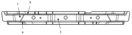
Fig. 2 is the scheme drawing (upward view) of the utility model chair mounted beam;
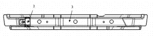
Fig. 3 is the connection diagram of the utility model fuel tank mounting bracket body and chair mounted beam;
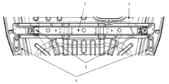
Fig. 4 is the connection diagram of the utility model chair mounted beam assembly and floor, back and floor side member;
Fig. 5 is the connection diagram on existing vehicle fuel tank mounting bracket and floor, back..
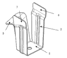
Among the figure: 1-be the floor, back, 2-be rack body, 3-be the chair mounted beam, 4-be floor side member, 5-be rectangular surfaces, 6-be first side, 7-be second side, 8-be the 3rd side; A, b-be the both sides inwall of chair mounted beam, c-be the diapire of chair mounted beam; 11-be floor, existing back, 12-for having rack body now.
The specific embodiment
Below in conjunction with accompanying drawing the utility model is further described.
Referring to Fig. 1, Fig. 2 and a kind of automotive oil tank mounting bracket assembly shown in Figure 3, comprise two identical rack bodies 2 and the back seat mounting rail 3 that connects with two rack bodies; Rack body 2 is a whole sheet metal component, and the lower end is that a rectangular surfaces 5 and centre are provided with a mounting hole, and a project-welding nut is corresponding with this mounting hole and be fixedly connected on rectangular surfaces;
The left side of rectangular surfaces 5 and vertical first side 6 link, the right and vertical second side 7 links, back and vertical the 3rd side 8 link; The upper end of the 3rd side 8 is provided with the flange of bending backward;
Be respectively equipped with vertical reinforced rib in described first side 6, second side 7 on the 3rd side 8; Adjacent regions in described first side 6 and the 3rd side 8 is provided with the technology breach, and the adjacent regions in described second side 7 and the 3rd side 8 also is provided with the technology breach.
Referring to Fig. 4, fuel tank cooperates with project-welding nut on two rack body lower end rectangular surfaces by bolt and is connected on two rack bodies 2, and two rack bodies and back seat mounting rail 3 are welded into an integral body.The centre portion of back seat mounting rail is linked together by a plurality of solder joints with floor 1, back, and the two end portions of back seat mounting rail and floor side member 4 are by a plurality of solder joint weld togethers.
This structure not only can increase substantially the rigidity of fuel tank attachment point, and the floor is not deformed; And chair mounted beam two ends and floor side member weld together can also improve the torsional strength of car load, improved occupant's traveling comfort, and occupant's life safety also is protected.
Fig. 5 is the connection diagram on existing vehicle fuel tank mounting bracket and floor, back.Existing rack body 12 directly is welded on the floor 11, existing back, and obviously, the weight that fuel tank also will be born in floor, existing back is so the rigidity at fuel tank attachment point position is very weak.
Claims (3)
1. automotive oil tank mounting bracket assembly, the back seat mounting rail (3) that comprises two identical rack bodies (2) and connect with two rack bodies; Rack body (2) is a whole sheet metal component, and the lower end is that a rectangular surfaces (5) and centre are provided with a mounting hole, and a project-welding nut is corresponding with this mounting hole and be fixedly connected on rectangular surfaces; It is characterized in that:
The left side of rectangular surfaces (5) and vertical first side (6) link, the right and vertical second side (7) links, back and vertical the 3rd side (8) link; The upper end of the 3rd side (8) is provided with the flange of bending backward;
First side (6) of two rack bodies (2) and the upper end of second side (7) are fixedly connected with the both sides inwall (a, b) of back seat mounting rail (3) respectively, and the flange of the upper end, the 3rd side (8) of two rack bodies (2) is fixedly connected with the diapire (c) of back seat mounting rail (3) respectively; A rack body is connected in the left part of back seat mounting rail, and another rack body is connected in the right part of back seat mounting rail.
2. a kind of automotive oil tank mounting bracket assembly according to claim 1 is characterized in that: be respectively equipped with vertical reinforced rib one on described first side (6), second side (7) and the 3rd side (8).
3. a kind of automotive oil tank mounting bracket assembly according to claim 1 and 2, it is characterized in that: the adjacent regions in described first side (6) and the 3rd side (8) is provided with the technology breach, and the adjacent regions in described second side (7) and the 3rd side (8) also is provided with the technology breach.
Priority Applications (1)
| Application Number | Priority Date | Filing Date | Title |
|---|---|---|---|
| CN2011200917309U CN201998789U (en) | 2011-03-31 | 2011-03-31 | Automobile fuel tank mounting support assembly |
Applications Claiming Priority (1)
| Application Number | Priority Date | Filing Date | Title |
|---|---|---|---|
| CN2011200917309U CN201998789U (en) | 2011-03-31 | 2011-03-31 | Automobile fuel tank mounting support assembly |
Publications (1)
| Publication Number | Publication Date |
|---|---|
| CN201998789U true CN201998789U (en) | 2011-10-05 |
Family
ID=44701555
Family Applications (1)
| Application Number | Title | Priority Date | Filing Date |
|---|---|---|---|
| CN2011200917309U Expired - Lifetime CN201998789U (en) | 2011-03-31 | 2011-03-31 | Automobile fuel tank mounting support assembly |
Country Status (1)
| Country | Link |
|---|---|
| CN (1) | CN201998789U (en) |
Cited By (3)
| Publication number | Priority date | Publication date | Assignee | Title |
|---|---|---|---|---|
| CN105667300A (en) * | 2016-01-27 | 2016-06-15 | 陈焕祥 | Gasoline tank protection device of tractor |
| CN108216873A (en) * | 2018-01-08 | 2018-06-29 | 北京金同泰科技有限公司 | Security device for fuel tank |
| CN114013269A (en) * | 2021-11-13 | 2022-02-08 | 安徽江淮汽车集团股份有限公司 | Oil tank mounting bracket |
-
2011
- 2011-03-31 CN CN2011200917309U patent/CN201998789U/en not_active Expired - Lifetime
Cited By (4)
| Publication number | Priority date | Publication date | Assignee | Title |
|---|---|---|---|---|
| CN105667300A (en) * | 2016-01-27 | 2016-06-15 | 陈焕祥 | Gasoline tank protection device of tractor |
| CN108216873A (en) * | 2018-01-08 | 2018-06-29 | 北京金同泰科技有限公司 | Security device for fuel tank |
| CN114013269A (en) * | 2021-11-13 | 2022-02-08 | 安徽江淮汽车集团股份有限公司 | Oil tank mounting bracket |
| CN114013269B (en) * | 2021-11-13 | 2024-03-08 | 安徽江淮汽车集团股份有限公司 | Oil tank installing support |
Similar Documents
| Publication | Publication Date | Title |
|---|---|---|
| CN105143020B (en) | Subframe for vehicle | |
| US8870224B2 (en) | Engine cradle with deflector device | |
| US9085329B2 (en) | Automotive rear vehicle body structure | |
| CN211519682U (en) | Vehicle front floor assembly and cross beam | |
| JP2012153258A (en) | Front body of vehicle | |
| CN103568771B (en) | Motorcar body with the externally-located reinforcer for connecting back axle | |
| CN103895535A (en) | Back installation beam assembly of front row seat of car | |
| CN201998789U (en) | Automobile fuel tank mounting support assembly | |
| CN104192215A (en) | Light electric automobile body structure | |
| CN202827805U (en) | Longitudinal-beam-free van semi trailer and compartment structure thereof | |
| CN201922879U (en) | Assembling structure for rear damper seat of automobile body | |
| CN103640546A (en) | Safety belt mounting structure of rear seat of automobile | |
| CN204415516U (en) | Fore sub frame mounting structure and automobile | |
| JP6042231B2 (en) | Front body structure of automobile | |
| JP2014144715A (en) | Front vehicle-body structure of vehicle | |
| CN202080123U (en) | Automobile fuel tank mounting bracket assembly | |
| JP6091876B2 (en) | Car suspension member reinforcement structure | |
| JP5509265B2 (en) | Body front structure | |
| CN215097819U (en) | Rear auxiliary frame | |
| CN210707669U (en) | Spare tire fixing device for vehicle and vehicle with same | |
| CN211918837U (en) | Inner reinforcing plate assembly of rear wheel cover | |
| CN209956066U (en) | Sub vehicle frame assembly behind high strength | |
| JP6925761B2 (en) | Vehicle front structure | |
| CN210793364U (en) | Automobile rear seat mounting beam | |
| CN101700789B (en) | Automobile rear floor bearing structure |
Legal Events
| Date | Code | Title | Description |
|---|---|---|---|
| C14 | Grant of patent or utility model | ||
| GR01 | Patent grant | ||
| CX01 | Expiry of patent term |
Granted publication date: 20111005 |
|
| CX01 | Expiry of patent term |