CN201858254U - 圆锥滚子轴承 - Google Patents
圆锥滚子轴承 Download PDFInfo
- Publication number
- CN201858254U CN201858254U CN 201020583791 CN201020583791U CN201858254U CN 201858254 U CN201858254 U CN 201858254U CN 201020583791 CN201020583791 CN 201020583791 CN 201020583791 U CN201020583791 U CN 201020583791U CN 201858254 U CN201858254 U CN 201858254U
- Authority
- CN
- China
- Prior art keywords
- inner ring
- retainer
- tapered roller
- bearing
- roller bearing
- Prior art date
- Legal status (The legal status is an assumption and is not a legal conclusion. Google has not performed a legal analysis and makes no representation as to the accuracy of the status listed.)
- Expired - Fee Related
Links
Images


Classifications
-
- F—MECHANICAL ENGINEERING; LIGHTING; HEATING; WEAPONS; BLASTING
- F16—ENGINEERING ELEMENTS AND UNITS; GENERAL MEASURES FOR PRODUCING AND MAINTAINING EFFECTIVE FUNCTIONING OF MACHINES OR INSTALLATIONS; THERMAL INSULATION IN GENERAL
- F16C—SHAFTS; FLEXIBLE SHAFTS; ELEMENTS OR CRANKSHAFT MECHANISMS; ROTARY BODIES OTHER THAN GEARING ELEMENTS; BEARINGS
- F16C35/00—Rigid support of bearing units; Housings, e.g. caps, covers
- F16C35/04—Rigid support of bearing units; Housings, e.g. caps, covers in the case of ball or roller bearings
- F16C35/06—Mounting or dismounting of ball or roller bearings; Fixing them onto shaft or in housing
- F16C35/063—Fixing them on the shaft
- F16C35/0635—Fixing them on the shaft the bore of the inner ring being of special non-cylindrical shape which co-operates with a complementary shape on the shaft, e.g. teeth, polygonal sections
-
- F—MECHANICAL ENGINEERING; LIGHTING; HEATING; WEAPONS; BLASTING
- F16—ENGINEERING ELEMENTS AND UNITS; GENERAL MEASURES FOR PRODUCING AND MAINTAINING EFFECTIVE FUNCTIONING OF MACHINES OR INSTALLATIONS; THERMAL INSULATION IN GENERAL
- F16C—SHAFTS; FLEXIBLE SHAFTS; ELEMENTS OR CRANKSHAFT MECHANISMS; ROTARY BODIES OTHER THAN GEARING ELEMENTS; BEARINGS
- F16C19/00—Bearings with rolling contact, for exclusively rotary movement
- F16C19/22—Bearings with rolling contact, for exclusively rotary movement with bearing rollers essentially of the same size in one or more circular rows, e.g. needle bearings
- F16C19/34—Bearings with rolling contact, for exclusively rotary movement with bearing rollers essentially of the same size in one or more circular rows, e.g. needle bearings for both radial and axial load
- F16C19/36—Bearings with rolling contact, for exclusively rotary movement with bearing rollers essentially of the same size in one or more circular rows, e.g. needle bearings for both radial and axial load with a single row of rollers
- F16C19/364—Bearings with rolling contact, for exclusively rotary movement with bearing rollers essentially of the same size in one or more circular rows, e.g. needle bearings for both radial and axial load with a single row of rollers with tapered rollers, i.e. rollers having essentially the shape of a truncated cone
Landscapes
- Engineering & Computer Science (AREA)
- General Engineering & Computer Science (AREA)
- Mechanical Engineering (AREA)
- Rolling Contact Bearings (AREA)
Abstract
本实用新型涉及一种圆锥滚子轴承,圆锥滚子轴承,包括内圈、保持架、滚子和外圈,外圈与内圈之间设置有保持架,滚子嵌入设置在保持架内,所述内圈的中心孔为正多边形柱孔。优点:本实用新型具有结构新颖,使用方便,所述内圈的中心孔位多边形柱孔,轴段与多边形柱孔匹配连接,其轴向通过压片固定,当需要拆卸时,仅需松开压片,即可将轴承取出。
Description
技术领域
本实用新型涉及一种轴承,特别是一种圆锥滚子轴承。
背景技术
现有技术中,圆锥滚子轴承由内圈、保持架、滚子和外圈构成,外圈与内圈之间设置有保持架,滚子嵌入设置在保持架内。其中,内圈的中心孔以及外圈的外壁均为圆柱面,通常所述内圈均与圆柱轴段连接,所述外圈与圆柱孔连接,轴和轴承连接,是轴与轴承的内圈套在一起,一般都是过盈配合(轴的直径略大于轴承内圈直径)。这样轴承的内圈紧密地套在轴上,成为一体。其不足之处是:轴与轴承内圈或者机件与轴承外圈装配或者拆卸时,均需要通过工具敲击,而在敲击过程中,容易损坏轴承。
发明内容
本实用新型的目的就是为了避免背景技术中的不足之处,提出一种结构新颖,安装和拆卸方便的圆锥滚子轴承。
对于本实用新型的一种优化,本实用新型采用如下技术方案:圆锥滚子轴承,包括内圈、保持架、滚子和外圈,外圈与内圈之间设置有保持架,滚子嵌入设置在保持架内,所述内圈的中心孔为正多边形柱孔。
本实用新型与背景技术相比,具有结构新颖,使用方便,所述内圈的中心孔位多边形柱孔,轴段与多边形柱孔匹配连接,其轴向通过压片固定,当需要拆卸时,仅需松开压片,即可将轴承取出。
附图说明
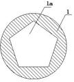
图1是圆锥滚子轴承的结构示意图。
图2是内圈的结构示意图之一。
图3是内圈的结构示意图之二。
图4是内圈的结构示意图之三。
具体实施方式
实施例1:参照图1~4。圆锥滚子轴承,包括内圈1、保持架2、滚子3和外圈4,外圈4与内圈1之间设置有保持架2,滚子3嵌入设置在保持架2内,所述内圈1的中心孔1a为正多边形柱孔。
实施例2:参照图2。所述内圈1的中心孔1a的截面为正三角形。
实施例3:参照图3。所述内圈1的中心孔1a的截面为正五角形。
实施例4:参照图4,所述内圈1的中心孔1a的截面为正六边形。
需要理解到的是:本实施例虽然对本实用新型作了比较详细的说明,但是这些说明,只是对本实用新型的简单说明,而不是对本实用新型的限制,任何不超出本实用新型实质精神内的发明创造,均落入本实用新型的保护范围。
Claims (1)
1.一种圆锥滚子轴承,包括内圈、保持架、滚子和外圈,外圈与内圈之间设置有保持架,滚子嵌入设置在保持架内,其特征是:所述内圈的中心孔为正多边形柱孔。
Priority Applications (1)
| Application Number | Priority Date | Filing Date | Title |
|---|---|---|---|
| CN 201020583791 CN201858254U (zh) | 2010-10-30 | 2010-10-30 | 圆锥滚子轴承 |
Applications Claiming Priority (1)
| Application Number | Priority Date | Filing Date | Title |
|---|---|---|---|
| CN 201020583791 CN201858254U (zh) | 2010-10-30 | 2010-10-30 | 圆锥滚子轴承 |
Publications (1)
| Publication Number | Publication Date |
|---|---|
| CN201858254U true CN201858254U (zh) | 2011-06-08 |
Family
ID=44104061
Family Applications (1)
| Application Number | Title | Priority Date | Filing Date |
|---|---|---|---|
| CN 201020583791 Expired - Fee Related CN201858254U (zh) | 2010-10-30 | 2010-10-30 | 圆锥滚子轴承 |
Country Status (1)
| Country | Link |
|---|---|
| CN (1) | CN201858254U (zh) |
Cited By (1)
| Publication number | Priority date | Publication date | Assignee | Title |
|---|---|---|---|---|
| CN108757727A (zh) * | 2018-06-15 | 2018-11-06 | 重庆交通大学 | 减振降冲轴承 |
-
2010
- 2010-10-30 CN CN 201020583791 patent/CN201858254U/zh not_active Expired - Fee Related
Cited By (1)
| Publication number | Priority date | Publication date | Assignee | Title |
|---|---|---|---|---|
| CN108757727A (zh) * | 2018-06-15 | 2018-11-06 | 重庆交通大学 | 减振降冲轴承 |
Similar Documents
| Publication | Publication Date | Title |
|---|---|---|
| EP2243685A3 (en) | Electric power steering system | |
| CN202702153U (zh) | 轴承装配器 | |
| SG159449A1 (en) | Spool shaft support structure for dual-bearing reel | |
| CN201858254U (zh) | 圆锥滚子轴承 | |
| CN201210042Y (zh) | 螺母光孔轴线垂直度检具 | |
| CN204019460U (zh) | 一种分离式轴承装配导向工装 | |
| CN203696190U (zh) | 一种可轴向滑动的旋转结构 | |
| CN203604262U (zh) | 通风机叶轮与电机轴伸配合固定结构 | |
| CN201461640U (zh) | 一种新型连接杆及连接球 | |
| CN202937664U (zh) | 执行机构的推力底座 | |
| WO2011135198A3 (fr) | Assemblage instrumente pour fusée d'essieu et procède de montage | |
| CN202228523U (zh) | 一种磁性球关节 | |
| CN201970265U (zh) | 一种巧取盲孔内套的装置 | |
| CN202579279U (zh) | 一种卧式多级泵滚动轴承的组合装置 | |
| CN202562502U (zh) | 用于轴承套圈支撑和转动的辅助检测装置 | |
| CN203892358U (zh) | 一种压轮 | |
| CN201412446Y (zh) | 带有紧定套“e”的调心滚子轴承 | |
| CN202625508U (zh) | 一种不同直径工字轮转换装置 | |
| CN204288949U (zh) | 成圈包膜一体机的转盘主轴安装结构 | |
| CN203044510U (zh) | 焊丝轧机用辊轮轴和轴承、轴承锁套的组合结构 | |
| CN201925333U (zh) | 轴承 | |
| CN203410241U (zh) | 一种新型自行车中轴结构 | |
| CN202851431U (zh) | 泵用轴承体结构 | |
| CN205708603U (zh) | 钢珠支座及扳动该钢珠支座的扳手 | |
| CN201209622Y (zh) | 外球面球轴承 |
Legal Events
| Date | Code | Title | Description |
|---|---|---|---|
| C14 | Grant of patent or utility model | ||
| GR01 | Patent grant | ||
| C17 | Cessation of patent right | ||
| CF01 | Termination of patent right due to non-payment of annual fee |
Granted publication date: 20110608 Termination date: 20121030 |