CN201858254U - Tapered roller bearing - Google Patents
Tapered roller bearing Download PDFInfo
- Publication number
- CN201858254U CN201858254U CN 201020583791 CN201020583791U CN201858254U CN 201858254 U CN201858254 U CN 201858254U CN 201020583791 CN201020583791 CN 201020583791 CN 201020583791 U CN201020583791 U CN 201020583791U CN 201858254 U CN201858254 U CN 201858254U
- Authority
- CN
- China
- Prior art keywords
- inner ring
- retainer
- tapered roller
- bearing
- roller bearing
- Prior art date
- Legal status (The legal status is an assumption and is not a legal conclusion. Google has not performed a legal analysis and makes no representation as to the accuracy of the status listed.)
- Expired - Fee Related
Links
Images


Classifications
-
- F—MECHANICAL ENGINEERING; LIGHTING; HEATING; WEAPONS; BLASTING
- F16—ENGINEERING ELEMENTS AND UNITS; GENERAL MEASURES FOR PRODUCING AND MAINTAINING EFFECTIVE FUNCTIONING OF MACHINES OR INSTALLATIONS; THERMAL INSULATION IN GENERAL
- F16C—SHAFTS; FLEXIBLE SHAFTS; ELEMENTS OR CRANKSHAFT MECHANISMS; ROTARY BODIES OTHER THAN GEARING ELEMENTS; BEARINGS
- F16C35/00—Rigid support of bearing units; Housings, e.g. caps, covers
- F16C35/04—Rigid support of bearing units; Housings, e.g. caps, covers in the case of ball or roller bearings
- F16C35/06—Mounting or dismounting of ball or roller bearings; Fixing them onto shaft or in housing
- F16C35/063—Fixing them on the shaft
- F16C35/0635—Fixing them on the shaft the bore of the inner ring being of special non-cylindrical shape which co-operates with a complementary shape on the shaft, e.g. teeth, polygonal sections
-
- F—MECHANICAL ENGINEERING; LIGHTING; HEATING; WEAPONS; BLASTING
- F16—ENGINEERING ELEMENTS AND UNITS; GENERAL MEASURES FOR PRODUCING AND MAINTAINING EFFECTIVE FUNCTIONING OF MACHINES OR INSTALLATIONS; THERMAL INSULATION IN GENERAL
- F16C—SHAFTS; FLEXIBLE SHAFTS; ELEMENTS OR CRANKSHAFT MECHANISMS; ROTARY BODIES OTHER THAN GEARING ELEMENTS; BEARINGS
- F16C19/00—Bearings with rolling contact, for exclusively rotary movement
- F16C19/22—Bearings with rolling contact, for exclusively rotary movement with bearing rollers essentially of the same size in one or more circular rows, e.g. needle bearings
- F16C19/34—Bearings with rolling contact, for exclusively rotary movement with bearing rollers essentially of the same size in one or more circular rows, e.g. needle bearings for both radial and axial load
- F16C19/36—Bearings with rolling contact, for exclusively rotary movement with bearing rollers essentially of the same size in one or more circular rows, e.g. needle bearings for both radial and axial load with a single row of rollers
- F16C19/364—Bearings with rolling contact, for exclusively rotary movement with bearing rollers essentially of the same size in one or more circular rows, e.g. needle bearings for both radial and axial load with a single row of rollers with tapered rollers, i.e. rollers having essentially the shape of a truncated cone
Landscapes
- Engineering & Computer Science (AREA)
- General Engineering & Computer Science (AREA)
- Mechanical Engineering (AREA)
- Rolling Contact Bearings (AREA)
Abstract
The utility model relates to a tapered roller bearing comprising an inner ring, a retainer, a roller and an outer ring, wherein the retainer is arranged between the outer ring and the inner ring; the roller is embedded in the retainer; and the center hole of the inner ring is an equilaterally polygonal cylindrical hole. The tapered roller bearing of the utility model has the advantages of being novel in structure and convenient for use; and as the center hole of the inner ring is the equilaterally polygonal cylindrical hole, an axis section is matched and connected with the polygonal cylindrical hole and the axial direction of the axis section is fixed through a pressing sheet, the bearing can be taken out by only loosening the pressing sheet when dismounting is needed.
Description
Technical field
The utility model relates to a kind of bearing, particularly a kind of tapered roller bearing.
Background technique
In the prior art, tapered roller bearing is made of inner ring, retainer, roller and outer ring, is provided with retainer between outer ring and the inner ring, and roller embeds and is arranged in the retainer.Wherein, the center hole of inner ring and the outer wall of outer ring are the cylndrical surface, and common described inner ring all is connected with the cylinder shaft part, described outer ring is connected with cylindrical hole, axle is connected with bearing, is spool that the inner ring with bearing is nested together, and generally all is interference fit (spool slightly larger in diameter in the bearing inner race diameter).The inner ring of bearing closely is enclosed within on the axle like this, becomes one.Its deficiency is: when axle and bearing inner race or parts and bearing outer ring assembling or dismounting, all need to knock by instrument, and in the process of knocking, damage bearing easily.
Summary of the invention
The purpose of this utility model is exactly the deficiency in the background technique, proposes a kind of novel structure, mounts and dismounts tapered roller bearing easily.
For a kind of optimization of the present utility model, the utility model adopts following technological scheme: tapered roller bearing, comprise inner ring, retainer, roller and outer ring, and be provided with retainer between outer ring and the inner ring, roller embeds and is arranged in the retainer, and the center hole of described inner ring is the regular polygon column hole.
The utility model is compared with background technique, has novel structure, and is easy to use, the polygonal post hole, center hole position of described inner ring, shaft part is connected with polygonal post hole coupling, and it is axially fixed by compressing tablet, when needs are dismantled, only need unclamp compressing tablet, bearing can be taken out.
Description of drawings
Fig. 1 is the structural representation of tapered roller bearing.
Fig. 2 is one of structural representation of inner ring.
Fig. 3 be inner ring structural representation two.
Fig. 4 be inner ring structural representation three.
Embodiment
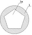
Embodiment 1: with reference to Fig. 1 ~ 4.Tapered roller bearing comprises inner ring 1, retainer 2, roller 3 and outer ring 4, is provided with retainer 2 between outer ring 4 and the inner ring 1, and roller 3 embeds and is arranged in the retainer 2, and the center hole 1a of described inner ring 1 is the regular polygon column hole.
Embodiment 2: with reference to Fig. 2.The cross section of the center hole 1a of described inner ring 1 is an equilateral triangle.
Embodiment 3: with reference to Fig. 3.The cross section of the center hole 1a of described inner ring 1 is positive pentagon.
Embodiment 4: with reference to Fig. 4, the cross section of the center hole 1a of described inner ring 1 is a regular hexagon.
What need understand is: though present embodiment is to the utility model detailed explanation of contrasting; but these explanations; just to simple declaration of the present utility model; rather than to restriction of the present utility model; any innovation and creation that do not exceed in the utility model connotation all fall into protection domain of the present utility model.
Claims (1)
1. a tapered roller bearing comprises inner ring, retainer, roller and outer ring, is provided with retainer between outer ring and the inner ring, and roller embeds and is arranged in the retainer, and it is characterized in that: the center hole of described inner ring is the regular polygon column hole.
Priority Applications (1)
| Application Number | Priority Date | Filing Date | Title |
|---|---|---|---|
| CN 201020583791 CN201858254U (en) | 2010-10-30 | 2010-10-30 | Tapered roller bearing |
Applications Claiming Priority (1)
| Application Number | Priority Date | Filing Date | Title |
|---|---|---|---|
| CN 201020583791 CN201858254U (en) | 2010-10-30 | 2010-10-30 | Tapered roller bearing |
Publications (1)
| Publication Number | Publication Date |
|---|---|
| CN201858254U true CN201858254U (en) | 2011-06-08 |
Family
ID=44104061
Family Applications (1)
| Application Number | Title | Priority Date | Filing Date |
|---|---|---|---|
| CN 201020583791 Expired - Fee Related CN201858254U (en) | 2010-10-30 | 2010-10-30 | Tapered roller bearing |
Country Status (1)
| Country | Link |
|---|---|
| CN (1) | CN201858254U (en) |
Cited By (1)
| Publication number | Priority date | Publication date | Assignee | Title |
|---|---|---|---|---|
| CN108757727A (en) * | 2018-06-15 | 2018-11-06 | 重庆交通大学 | Vibration damping drop rushes bearing |
-
2010
- 2010-10-30 CN CN 201020583791 patent/CN201858254U/en not_active Expired - Fee Related
Cited By (1)
| Publication number | Priority date | Publication date | Assignee | Title |
|---|---|---|---|---|
| CN108757727A (en) * | 2018-06-15 | 2018-11-06 | 重庆交通大学 | Vibration damping drop rushes bearing |
Similar Documents
| Publication | Publication Date | Title |
|---|---|---|
| EP2009302A3 (en) | Bearing fixing device and bearing unit | |
| EP2243685A3 (en) | Electric power steering system | |
| SG159449A1 (en) | Spool shaft support structure for dual-bearing reel | |
| CN201858254U (en) | Tapered roller bearing | |
| CN201210042Y (en) | Checking tool for verticality of nut unthreaded hole shaft line | |
| CN201771981U (en) | Bearing seat structure of shaft piece | |
| CN204019460U (en) | A kind of pedestal assembling guided tooling | |
| CN201461640U (en) | Novel connecting rod and connecting ball | |
| CN202937664U (en) | Thrust base of actuating mechanism | |
| CN202639355U (en) | Strong running center | |
| CN201970265U (en) | Device for taking sleeve out of blind hole skillfully | |
| CN204686788U (en) | The provision for disengagement of a kind of torque-converters transfer gear | |
| CN204677603U (en) | Drawn cup is centripetal with needle roller thrust combination bearing | |
| CN202579279U (en) | Device for combining horizontal type multi-stage pump rolling bearing | |
| CN205841690U (en) | The axle mounting structure of granulator | |
| CN203892358U (en) | Pressing wheel | |
| CN202625508U (en) | Different diameter I-shaped wheel conversion device | |
| CN204288949U (en) | The rotating disk spindle mounting structure of lopping coating all-in-one | |
| CN203044510U (en) | Composite structure of roller shaft, bearing and bearing lock sleeve for solder wire rolling mill | |
| CN202867316U (en) | Four-jaw coupling | |
| CN201925333U (en) | Bearing | |
| CN203410241U (en) | Novel middle axle structure of bicycle | |
| CN202851431U (en) | Bearing body structure for pump | |
| CN205708603U (en) | Steel ball bearing and pull the spanner of this steel ball bearing | |
| CN202562502U (en) | Assistant detecting device employed to support and rotation of bearing ring |
Legal Events
| Date | Code | Title | Description |
|---|---|---|---|
| C14 | Grant of patent or utility model | ||
| GR01 | Patent grant | ||
| C17 | Cessation of patent right | ||
| CF01 | Termination of patent right due to non-payment of annual fee |
Granted publication date: 20110608 Termination date: 20121030 |