CN1532402A - Support structure of portable air compressor - Google Patents
Support structure of portable air compressor Download PDFInfo
- Publication number
- CN1532402A CN1532402A CNA2004100088396A CN200410008839A CN1532402A CN 1532402 A CN1532402 A CN 1532402A CN A2004100088396 A CNA2004100088396 A CN A2004100088396A CN 200410008839 A CN200410008839 A CN 200410008839A CN 1532402 A CN1532402 A CN 1532402A
- Authority
- CN
- China
- Prior art keywords
- framework
- air compressor
- compressor assembly
- motor
- dunnage
- Prior art date
- Legal status (The legal status is an assumption and is not a legal conclusion. Google has not performed a legal analysis and makes no representation as to the accuracy of the status listed.)
- Granted
Links
Images


Classifications
-
- F—MECHANICAL ENGINEERING; LIGHTING; HEATING; WEAPONS; BLASTING
- F04—POSITIVE - DISPLACEMENT MACHINES FOR LIQUIDS; PUMPS FOR LIQUIDS OR ELASTIC FLUIDS
- F04B—POSITIVE-DISPLACEMENT MACHINES FOR LIQUIDS; PUMPS
- F04B35/00—Piston pumps specially adapted for elastic fluids and characterised by the driving means to their working members, or by combination with, or adaptation to, specific driving engines or motors, not otherwise provided for
- F04B35/06—Mobile combinations
Abstract
A portable air compressor assembly includes a tubular frame having a pair of parallelogram shaped side sections. A support plate is connected between the side sections and horizontally positioned in a compressor normal operating position. A plurality of operating components connect to the support plate. A fluid pressure tank is supported perpendicular to the side sections and forward of the operating components. The frame envelopes the operating components' outer perimeter and angularly extends to a stop point rearward of the operating components. When tipped rearward to the stop point, the compressor assembly returns by gravity to the compressor normal operating position. An instrument and connector panel including an engine on/off switch is mounted in a protected position. Wheels and structural feet are removable and a handle is retractable and removable for shipping.
Description
Technical field
The present invention relates generally to air compressor, is specifically related to the supporting structure of portable air compressor.
Background technique
Generally as source of compressed air, these pressurized air are stored in the compressed tanks air compressor temporarily.The actuator that is generally motor or internal-combustion engine is connected to compressor bank.Compressor bank generally comprises a piston assembly or compressor pump, and the compression of piston assembly or compressor pump is from the air of atmosphere and force it to enter the fluid pressure tank that is used for interim storage.Use in order to make air compressor conveniently move to the working site, structural framing is provided.Framework generally comprises at least one wheel that is used for mobile air compressor assembly.
There are some defectives in portable air compressor assembly commonly used.First defective is the constituent elements of air compressor assembly, and the refrigerating head of parts of air-strainer of petrol engine silencing apparatus and petrol engine and so on and compressor for example often is arranged in the outside of structural housing of the framework of support air compressor assembly.The part that some other is less, for example the exhaust of fluid pressure tank and liquid discharging valve, the self contained instrument that is used for definite system pressure and liquid port of various different operating elements or the like also are exposed to outside (just extending to the outside of frame shell) through regular meeting.The element that exposes is damaged easily.
Another defective of known portable air compressor is, pushing away by handle or tension and compression when contracting the air engine assembly, and assembly is easy to overturning.Be used to support and be used to make the wheel that framework moves and make that also whole assembly is easy to rotate and overturning.When the air compressor assembly overturning, those parts that reach outside the frame perimeter may be damaged, and also fuel leak may take place.
Therefore, be desirable to provide a kind of portable air compressor assembly that has overcome the defective of known air compressor assembly.
Summary of the invention
In a preferred embodiment of the invention, the portable air compressor assembly comprises a framework with pair of parallel lateral parts.At the compressor normal operating position, a dunnage flatly is connected between two lateral parts.A plurality of operating elements are connected to dunnage.The fluid pressure tank vertical support is to lateral parts and in the place ahead of operating element.The outer periphery of frame facet part encapsulating operation element, and angle extends to the framework rotation halt of operating element back.When rotating halt when toppling over towards framework backward, gravity makes compressor assembly turn back to the compressor normal operating position.
In a further advantageous embodiment, the supporting structure of portable air compressor comprises a framework with a pair of approximately parallel lateral parts, and a dunnage that is horizontally set between the lateral parts.The a plurality of elements that comprise motor, compressor and fluid pressure tank are connected to dunnage.A wheel shaft passes the following tubular portion of two lateral parts slidably, and wheel shaft has the end of the opposite planar shell that operationally forms portable air compressor.The meter support panel can be connected on the framework, and is positioned at a select location of adjacent plane shell.Comprise that motor on/off switch, at least one pressure gauge, a plurality of instrument that at least one disconnects accessory and at least one feather valve fast are installed on the meter support panel, make each instrument and meter support panel can fully be positioned at a selected outerplanar shell.
The wheel and the structural feet that are supported on rotationally on the wheel shaft are used for supporting component, and each can take off so that transport.The center of gravity of assembly is positioned at the place ahead of wheel, and when toppling over backward with convenient assembly, center of gravity still remains on the place ahead of the vertical axis that passes wheel shaft, and gravity makes assembly deflection, makes it turn back to normal operating position.In another preferred embodiment, lateral parts provides a pair of lifting handle of assembly.In another preferred embodiment, the handle that is arranged on the central position can withdraw or take off, so that transport.
From following detailed description, can know other advantage of the present invention.Although should be known in detailed explanation and specific examples and pointed out the preferred embodiments of the present invention, just for illustrative purposes, rather than to limit the scope of the invention.
Description of drawings
From following detailed description and accompanying drawing, can understand the present invention more fully, wherein:
Fig. 1 is the perspective view of a preferred embodiment of air compressor assembly of the present invention;
Fig. 2 is the planimetric map of the assembly of Fig. 1, shows the orientation of fluid storage tank with respect to the assembly longitudinal shaft;
Fig. 3 is along the side view of the section 3 of Fig. 2, shows the control panel that is installed to frame structure;
Fig. 4 is along the side view of the section 4 of Fig. 2, shows the relation between wheel of the present invention and the supporting foot, and the assembly center of gravity;
Fig. 5 is the side view of Fig. 4, shows compressor assembly turns to framework around wheel shaft the definite stop position of back projection;
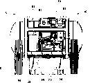
Fig. 6 be show be installed in two on the dunnage between the lateral parts exemplary engine and the planimetric map of compressor;
Fig. 7 is the side view of the section 7 of Fig. 6, and all elements that show motor and air compressor all are enclosed in the shell of framework;
Fig. 8 is the rear view of the section 8 of Fig. 7, the geometrical shape of wheel shaft that shows supporting foot and pass the tubular member of framework rotationally;
Fig. 9 is the bottom view along the compressor assembly of the section 9 of Fig. 7, has shown lower supporting plate in detail and has been used for the installation fastening piece of device support to dunnage;
Figure 10 is the perspective view of another preferred embodiment of the present invention, and this embodiment has the framework that is connected to fluid pressure tank on the structure and the preceding support handle of centralized positioning; With
Figure 11 is with the flow chart of portable air compressor of the present invention to the method for levels operation location deflection.
Embodiment
On the illustrative in nature of following preferred embodiment only is to illustrate for example, rather than will limit the present invention and application or use by any way.
Fig. 1 shows air compressor assembly 10 according to a preferred embodiment of the present invention.Air compressor assembly 10 comprises a framework 12, an element group 14 and a fluid pressure tank 16.The first round 18 and second takes turns 20 and is supported on the rear end of air compressor assembly 10 rotationally from framework 12.Framework 12 comprises one first lateral parts 22 and one second lateral parts 24.First lateral parts 22 and second lateral parts 24 are the tubular frame members that forms the parallelogram with fillet generally.Dunnage 26 is provided at the bottom of framework 12, and mechanically is attached to first lateral parts 22 and second lateral parts 24 respectively.A pair of supporting foot 28 (only can see one among this figure) mechanically is attached to the front end of framework 12 at the lower surface of dunnage 26, and this point will illustrate in greater detail with reference to figure 9 time.
Each supporting foot 28 comprises a cushion 30.The purpose of cushion 30 is the slips that will reduce air compressor assembly 10 when power operation, and anti-locking apparatus slides on being placed on relative smooth surface the time.Control panel 32 is provided on any one lateral parts in first lateral parts 22 or second lateral parts 24.In the embodiment shown, control panel 32 is by the last level of first lateral parts 22 and the support of following plane member.Further specify control panel 32 with reference to figure 3.Supporting member 34 after providing one among the present invention, so that first lateral parts, 22 structures are connected to second lateral parts 24.As illustrating in greater detail with reference to figure 5, back supporting member 34 also rotates the part of halt as the framework of framework 12 kiss the earths.In a preferred embodiment, back supporting member 34 and dunnage 26 all are welded to first lateral parts 22 and second lateral parts 24.
As shown in Figure 2, the structure of framework 12 makes it possible to element group 14 is completely enclosed within the shell of framework 12.Assembly longitudinal axis A is with 12 pairs of branches of framework.Fluid pressure tank 16 comprises a jar longitudinal axis B approximately perpendicular to assembly longitudinal axis A.
As shown in Figure 3, control panel 32 is supported on the two ends up and down of framework 12.In a preferred embodiment, control panel 32 in binding site 33 mechanical fixation (for example welding) to framework 12.In Fig. 3, control panel 32 is shown as vertical orientation, still, also can uses the mechanical fixation combination that is similar to binding site 33, control panel 32 is supported to the last horizontal component or the following horizontal component of framework 12 along a major opposing side.A plurality of elements are installed on the control panel 32.Specifically, control panel comprises that at least one pressure gauge 36, air regulator regulate button 37, feather valve 38, a motor on/off switch 39 and an a pair of quick disconnection accessory 40.Pressure gauge 36, feather valve 38, on/off switch and the element that disconnects accessory 40 and so on fast can have various arrangement on control panel 32.
As shown in Figure 4, back tubular member 41 is connected to down horizontal pipe with first lateral parts, 22 (not shown) of framework 12 and the last horizontal pipe of second lateral parts 24.As shown in the figure, each back tubular member 41 forms a framework relief angle θ with ground C.Framework relief angle θ makes air compressor assembly 10 to take turns the rotatingshaft D at each center of taking turns of 20 and rotate around being formed on the first round 18 (not shown) and second.Wheel shaft vertical axis E extends from running shaft D.Center of gravity 42 is arranged on the place ahead of axletree vertical axis E.The position of the air compressor assembly 10 shown in Fig. 4 is to take turns 20 and the normal operating position of each supporting foot 28 kiss the earth C each first round 18 and second.Those skilled in the art should be known in that the geometrical shape of ground C can change so, thereby normal operating position also can be changed as long as each is taken turns and supporting foot kiss the earth C.In addition, as shown in Figure 4, second took turns for 50 (and unshowned first round 18) is in the position of rearmost part of the following horizontal pipe of framework 12.As shown in the figure, fluid pressure tank 16 is positioned at the top of supporting foot 28.Therefore, wheel 18,20 and supporting foot 28 are provided on the position that is configured in the heaviest contiguous element of framework 12, with the element of support air compressor assembly 10 suitably.Preceding and rear described here to be with respect to arrow F forwards to.
As shown in Figure 5, air compressor assembly 10 rotates promoting the sense of rotation H moving axis D that rotates, up to back tubular member 41 and/or back supporting member 34 kiss the earth C.Point of contact between framework 12 and ground C shows framework and rotates halt 44.Pivotal position shown in Figure 5, center of gravity 42 is retained in the place ahead of wheel shaft vertical axis E.On this position, framework 12 has rotated an assembly rotational angle φ from ground C.At assembly rotation angle φ, gravity can make air compressor assembly 10 rotate moving axis D returning sense of rotation J upper deflecting, turns back to normal operating position shown in Figure 4.Under the condition with level ground C shown in Figure 5, largest component rotation angle φ depends on the radius Y of distance X between the rear end that comprises (with reference to figure 4) wheel shaft vertical axis E and framework 12, wheel and rotates several variablees of the height Z of halt 44 from ground C to framework.
With reference to figure 4, there is shown the total height T and the total length V of air compressor assembly 10 again.In a preferred embodiment, total height T is approximately 50cm (20 inches), and total length V is approximately 119cm (47 inches).Should be known in to change these sizes of the present invention, and do not break away from the spirit and scope of the present invention.
As shown in Figure 6, show petrol power reciprocating engine 50 and compressor pump 52.Motor 50 comprises a drive pulley 54 that is connected to the rotating pulley 56 of compressor pump 50 by the V-shape belt (not shown).Suitably select the layout of motor 50, compressor pump 52 and fluid pressure tank 16, so that on assembly longitudinal axis A, roughly distribute the weight of these elements equably.First lateral parts 22 provides a traction/raised position 58, the second lateral parts 24 that a traction/raised position 60 is provided, so that from the front end hand hoisting and the mobile air compressor assembly 10 of compressor assembly 10.But, can promote air compressor assembly 10 from traction/raised position 58 or 60 respectively, so that on the opposite direction of F, promote air compressor assembly 10, be preferably and hold traction/raised position 58 and 60 simultaneously forwards.In an illustrated embodiment, a pair of carriage 61 leaves framework 12 with fluid pressure tank 16 local support, and carriage 61 is mechanically connected on each connecting sheet of a pair of connecting sheet 60 that is welded to fluid pressure tank 16.
As shown in Figure 7, comprise that the element at rear portion of the motor 50 of silencing apparatus 63 is positioned at the shell of framework 12.The compressor body 64 and the refrigerating head 66 of compressor 52 also are assemblied in the shell of framework 12.This layout has reduced outside the protection border that these elements reach framework 12 and has caused the possibility of damage.
With reference now to Fig. 8,, at length shows fluid pressure tank 16 is supported to carriage 61 and connecting sheet 62 on the framework 12.The hole that wheel shaft 46 passes the rear end of the close compressor assembly 10 in the following plane member of first lateral parts 22 that is formed on framework 12 and second lateral parts 24 is rotatably positioned.Also show the geometrical shape and the structure of supporting foot 28 among the figure.As describing in detail with reference to figure 9, the construction machine of supporting foot 28 is fixed to dunnage 26.Supporting foot 28 has formed the part of supporting structure 68, and supporting structure 68 comprises arched part 70, to separate each supporting foot 28.When ground C from shown in horizontal plane when changing, arched part 70 makes air compressor assembly 10 keep static, and each supporting foot 28 contacts with ground C.
As shown in Figure 9, the lower surface of air compressor assembly 10 provides Support Position for first lateral parts 22 and second lateral parts, 24 each lateral parts respectively for dunnage 26.A plurality of solder joints 72 are connected to each lateral parts in first lateral parts 22 and second lateral parts 24 with the some parts of dunnage 26.Can be through being formed on the hole 76 that forms in the supporting structure 68 near the liquid discharging valve 74 of fluid pressure tank 16.The elevated regions 78 of the contiguous liquid discharging valve 74 of supporting structure 68 provides extra protection for the part that liquid discharging valve 74 extends to below fluid pressure tank 16 excircles.Supporting structure 68 is connected to fluid pressure tank 16 through a plurality of fastening pieces 80 and connecting sheet (not shown).As shown in Figure 7, compressor 52 is installed to dunnage 26 through a plurality of fastening pieces 82.The discharge opeing accessory (not shown) of compressor 52 is aimed at the outage 84 that passes dunnage 26, so that discharge the lubricating fluid of compressor 52.Similar to shown in Fig. 7, motor 50 is installed to dunnage 26 through a plurality of fastening pieces 86.The discharge opeing accessory 88 of motor 50 has the outage of aiming at it 90, so that allow the lubricating fluid of motor 50 to discharge.
With reference to Figure 10, show the air compressor assembly 100 of another preferred embodiment of the present invention.Air compressor assembly 100 is identical with air compressor assembly 10, comprises a framework 102, an element group 104 and a fluid pressure tank 106.Shown other element that comprises wheel and control panel is identical with those elements of air compressor assembly 10, therefore here discusses no longer further.Framework 102 comprises it generally being first lateral parts 108 and second lateral parts 110 that is formed by tubular material.Each lateral parts in first lateral parts 108 and second lateral parts 110 has end 109 and 111, and from the planimetric map of air compressor assembly 100, terminal 109 and 111 align with the longitudinal axis of fluid pressure tank 106 respectively approx.First end of a pair of connecting sheet 112 is connected to first lateral parts 108 and second lateral parts 110 by in a pair of fastening piece 114 each, and is welded to fluid pressure tank 106 at second end.Therefore, framework 102 is connected the upper surface and the lower surface of fluid pressure tank 106, and partly relies on the rigidity of fluid pressure tank 106 to force framework 102.Framework 102 also comprises a center lift portion 116 with the assembly longitudinal axis (identical with the assembly longitudinal axis A of air compressor 10) approximate alignment at the front end of air compressor assembly 100.Center lift portion 116 makes it possible to push away or draw air compressor assembly 100 along the longitudinal axis of air compressor assembly 100.As selection, can forwards reach (shown in the dotted line) extended position to center lift portion 116 from (shown in) stowed position, and be locked in extended position to F.In addition, can integrally take off the center lift portion.Center lift portion 116 is locked in such as spring loaded pin hidden or the mechanical locking of extended position is known, therefore do not do further discussion here.For center lift portion 116 can be stretched out, the diameter that make center lift portion 116 less than or greater than the two diameter of first lateral parts 108 and second lateral parts 110.
Apply the method step of deflecting force at last to compressor assembly of the present invention with reference to Figure 11 explanation.In beginning step 200, calculate the center of gravity of compressor assembly.In step 202, a pair of wheel that has common rotation axis and pass the vertical axis of common rotation axis is positioned at the rear of center of gravity.In later step 204, with the rear extension of framework contact surface to the common rotation axis of wheel.At next step 206, lifting handle is arranged on the place ahead of center of gravity.In step 208, the rotate path of definition compressor assembly, when using lifting handle to make compressor assembly when common rotation axis rotates, rotate path changes between normal operating position and pivotal position, and the pivotal position makes framework contact surface kiss the earth.In last step 210, pre-determine the position of framework contact surface, so that on whole compressor assembly rotate path, make center of gravity remain on the place ahead of vertical axis, make gravity compressor assembly to be got back to normal operating position from pivotal position deflection in any position along rotate path of compressor assembly.
Air compressor assembly of the present invention has lot of advantages.The select location of afterframe geometrical shape and device center of gravity has reduced the possibility of air compressor assembly overturning jointly.Gravity biased makes device turn back to normal operating position.The framework of air compressor assembly provides the space of complete closed, has protected the equipment of frame supported.In the planar housings that the wheel axle end surface that control panel of the present invention makes all instrument mounted thereto be included in the support wheel forms.This has reduced to damage any possibility that is installed in the element on the control panel.The hole is provided on dunnage,, and provides the path that is used for discharge opeing of operating fluid pressurized tank and outlet valve so that from compressor and engine emission fluid.A plurality of strong points can be used for different frames embodiment of the present invention,, and not make the device overturning so that can promote or pull unit.The little spatial enclosure of assembly of the present invention makes it possible to whole device is placed in the compartment of the commercial truck of using in the building industry.The wheel of air compressor assembly, supporting foot and front hand grip can be removed, so that shifter and packing device.
Explanation of the present invention in fact only is to illustrate for example, and therefore, the various changes that do not break away from main idea of the present invention comprise within the scope of the invention.These changes can not be regarded as and break away from the spirit and scope of the present invention.
Claims (28)
1. portable air compressor assembly comprises:
One has a pair of tubular frame that has defined the abundant parallel lateral parts of a front end, a rear end and an enclosed space volume;
A dunnage that is arranged between the described lateral parts, described dunnage horizontal location is at the normal operating position of described air compressor assembly;
A plurality of operating elements that are arranged on described dunnage and contiguous described back-end framework joinably, described operating element has defined a combination shell that is included in fully in the described enclosed space volume;
A fluid pressure tank that is arranged on contiguous described framework front position on the described dunnage; With
An angle extension that when working, has formed the described framework of a framework rotation stopper at described back-end framework, thereby when described compressor assembly turns to described rotation stopper, make described angle extension kiss the earth, thereby limited the further rotation of described compressor assembly.
2. air compressor according to claim 1 further comprises a front hand grip part that is releasably connected to the described front end of described framework, and described front hand grip part is joinably in conjunction with described lateral parts.
3. air compressor according to claim 1, wherein said framework have a holding position that is arranged on the described front end of each described parallel side described framework of vicinity partly.
4. air compressor according to claim 1, wherein said operating element further comprise the motor that is supported on the described dunnage and at least one in the motor; With one with described at least one motor and motor together support on the described dunnage and compressor pump that drive during by described at least one motor and motor in work.
5. air compressor according to claim 4, the setting type that wherein has described at least one motor and motor and a compressor is: the contiguous described back-end framework of at least one motor and motor, and described compressor is positioned at the place ahead of described at least one motor and motor; And a plurality of machanical fasteners support to described dunnage joinably with in described at least one motor and motor and the described compressor each.
6. air compressor according to claim 1 further comprises:
A wheel shaft that passes slidably near the following tubular portion of each lateral parts of described back-end framework, described wheel shaft has opposing ends and a longitudinal axis; With
A wheel is set on the described end of each of described wheel shaft, and described wheel has the coaxillay aligned center of rotation of the described longitudinal axis with described wheel shaft.
7. air compressor according to claim 6, wherein center of gravity is positioned at described wheel shaft the place ahead when normal operating position, and when described compressor when described wheel shaft rotates, center of gravity remains on from the place ahead of the vertically extending axis of described wheel shaft.
8. air compressor according to claim 1 further comprises:
One the time is arranged on fluid pressure tank liquid discharging valve on the lower surface of described fluid pressure tank in work;
Supporting structure with the supporting foot that is provided with near described framework front end; With
One that stretch out from described supporting structure, make described liquid discharging valve be arranged on convex area wherein fully.
9. supporting frame that is used for portable air compressor comprises:
One has a pair of approximately parallel lateral parts and a framework that is horizontally set on the dunnage between the described lateral parts;
A plurality of elements that are arranged on joinably on the described dunnage;
A wheel shaft that passes the following tubular portion of two described lateral parts slidably, described wheel shaft have the end that forms the relative outerplanar shell of described portable air compressor when work;
A meter support plate that is arranged on the described framework joinably and is close to one of described outerplanar shell location; With
A plurality of instrument that are installed on the described meter support plate, make each instrument and described meter support plate in described a plurality of instrument be positioned at a described outerplanar shell fully, described a plurality of instrument comprise at least one pressure gauge, at least one disconnects accessory and a motor on/off switch fast.
10. supporting frame according to claim 9 comprises that further at least one is attached to described dunnage the mechanical fasteners point of each described lateral parts joinably.
11. supporting frame according to claim 9, further comprise a handle that is connected to described framework slidably, described handle has one described supporting structure stretching out fully and locked position between the spreadable life, and one at the described complete retracted position that transports in the configuration.
12. supporting frame according to claim 9 further comprises:
Has a lateral parts that forms the body of parallelogram structure separately with fillet;
An adpting flange that is attached to each described body; With
Fluid pressure tank with a pair of mechanical bond in the engagement tabs of the outer surface of described fluid pressure tank, each described engagement tabs can be mechanically connected to a described adpting flange.
13. supporting frame according to claim 9 further comprises at least two holes that are formed on the described dunnage, a described hole is aimed at the engine fluid liquid port, and another described hole is aimed at the compressor fluid liquid port.
14. supporting frame according to claim 9, further comprise a construction element that is releasably connected to described dunnage, described construction element has contact extension, at least one ground and one and is arranged on wheel on the described end of each described wheel shaft rotationally; Wherein in transporting configuration, take off to the described construction element of major general, described wheel and described wheel shaft.
15. supporting frame according to claim 9 further comprises at least one in motor and the motor; And at least one is arranged on the mechanical bond point between described at least one motor and motor and the described dunnage.
16. supporting frame according to claim 9 further comprises a fluid pressure tank with a longitudinal shaft, described fluid pressure tank is installed to dunnage, makes the longitudinal shaft of fluid pressure tank in fact perpendicular to the longitudinal shaft orientation of described supporting frame.
17. a self-stabilization portable air compressor assembly comprises:
One has a pair of approximately parallel, the framework that comprises the tubulose lateral parts of a front end and a rear end, and described framework has the angle extension of location, a described rear end of vicinity;
A dunnage that in normal operating position, is horizontally set between the described lateral parts;
A plurality of elements that are arranged on joinably on the described dunnage;
A following tubular portion that passes described lateral parts in described rear end slidably, and have a pair of wheel shaft that supports wheel thereon rotationally; With
A center of gravity that is arranged on described wheel shaft the place ahead in normal operating position is when described compressor assembly center of gravity when described wheel shaft rotates remains on from the place ahead of the vertically extending axis of described wheel shaft.
18. air compressor assembly according to claim 17 further comprises a pair of rigid support pin that removably is connected to described framework and contiguous described framework front end.
19. air compressor assembly according to claim 18 further comprises a cushion that is arranged on each described supporting foot.
20. air compressor assembly according to claim 17, further comprise a rotation halt that is formed between described angle extension and the described ground, the deflection owing to gravity of wherein said compressor assembly is to turn back to described normal level operating position from described pivotal position.
21. air compressor assembly according to claim 17, wherein said framework have defined a longitudinal shaft, fully are distributed to mode on the described longitudinal shaft thereby make it possible to weight with described a plurality of elements, longitudinally axle is arranged described a plurality of elements.
22. air compressor assembly according to claim 21 comprises that further at least one is formed on the support handle of described framework front end, wherein said at least one support handle has the center lift point, and described longitudinal shaft passes described center lift point.
23. air compressor assembly according to claim 21, wherein said framework each the described lateral parts with described longitudinal shaft equidistant intervals comprise one forward radially bend part.
24. a method that makes the portable air compressor assembly to the levels operation location deflection comprises the steps:
Calculate the center of gravity of compressor assembly;
With a pair of rear with wheel alignment of common rotation axis in center of gravity;
The framework contact surface is extended to the rear of the common rotation axis of wheel;
Lifting handle is arranged on the place ahead of center of gravity;
The rotate path of the compressor assembly that definition can change between a normal operating position and pivotal position; With
Pre-aligned framework contact surface, in normal operating position, to make center of gravity remain on the place ahead of vertical shaft, with in the pivotal position, remain on from the place ahead of the vertically extending axis of common rotation axis, thereby gravity makes compressor assembly deflection, turns back to normal operating position from the pivotal position.
25. method according to claim 24 comprises:
Rotationally wheel support is being taken turns the tip of the axis; With
The manipulator of air compressor is installed in the operation housing of the compressor assembly with the border that is formed on the wheel shaft end.
26. method according to claim 25 comprises the instrument front that compressor assembly is installed, and makes that all instrument on the panel are positioned at operation housing.
27. method according to claim 24 comprises:
Around common rotation axis center of gravity is set rotationally; With
The pivotal position is limited in the maximum magnitude that the framework contact surface of kiss the earth defines.
28. method according to claim 24 comprises extended and removable arm is arranged on the lifting handle.
Applications Claiming Priority (2)
| Application Number | Priority Date | Filing Date | Title |
|---|---|---|---|
| US10/392,567 | 2003-03-20 | ||
| US10/392,567 US7029240B2 (en) | 2002-10-10 | 2003-03-20 | Support structure for a portable air compressor |
Publications (2)
| Publication Number | Publication Date |
|---|---|
| CN1532402A true CN1532402A (en) | 2004-09-29 |
| CN100400872C CN100400872C (en) | 2008-07-09 |
Family
ID=32824886
Family Applications (1)
| Application Number | Title | Priority Date | Filing Date |
|---|---|---|---|
| CNB2004100088396A Expired - Fee Related CN100400872C (en) | 2003-03-20 | 2004-03-22 | Support structure of portable air compressor |
Country Status (5)
| Country | Link |
|---|---|
| US (2) | US7029240B2 (en) |
| EP (1) | EP1460269B1 (en) |
| CN (1) | CN100400872C (en) |
| DK (1) | DK1460269T3 (en) |
| ES (1) | ES2428890T3 (en) |
Cited By (5)
| Publication number | Priority date | Publication date | Assignee | Title |
|---|---|---|---|---|
| CN102177385A (en) * | 2008-10-07 | 2011-09-07 | 创科电动工具科技有限公司 | Portable air compressor |
| CN101280774B (en) * | 2007-04-02 | 2012-07-04 | 创科电动工具科技有限公司 | Portable air compressor |
| CN102878055A (en) * | 2012-09-28 | 2013-01-16 | 樊荣 | Portable air pump |
| CN105587657A (en) * | 2016-03-03 | 2016-05-18 | 隆鑫通用动力股份有限公司 | Handlebar pipe of water pump installation frame |
| CN109901236A (en) * | 2019-03-05 | 2019-06-18 | 赵秀军 | A kind of detection instrument with safeguard function for iron ore |
Families Citing this family (25)
| Publication number | Priority date | Publication date | Assignee | Title |
|---|---|---|---|---|
| US7163382B1 (en) * | 2003-04-09 | 2007-01-16 | Black & Decker Inc. | Suitcase style air compressor assembly |
| US7029240B2 (en) * | 2002-10-10 | 2006-04-18 | Black & Decker Inc. | Support structure for a portable air compressor |
| US7025573B1 (en) * | 2003-04-09 | 2006-04-11 | Black & Decker Inc. | Storage container for air compressor |
| US20060104835A1 (en) * | 2003-04-09 | 2006-05-18 | Etter Mark A | Portable air compressor tool carrier |
| US7909584B2 (en) * | 2004-01-30 | 2011-03-22 | Black & Decker Inc. | Air compressor |
| US7384245B2 (en) * | 2004-11-01 | 2008-06-10 | Alltrade Tools Llc | Compressor with rotating handle |
| US20060171820A1 (en) | 2005-01-31 | 2006-08-03 | Baron Michael P | Cooling arrangement for a portable air compressor |
| KR100646004B1 (en) * | 2005-02-25 | 2006-11-23 | (주)오티 웰빙 | Air compressor an improved model |
| US20060228228A1 (en) * | 2005-03-21 | 2006-10-12 | Wesolowski Gregory G | Engine mounting frame |
| DE102005018757B4 (en) * | 2005-04-24 | 2014-07-24 | SHG Spechtenhauser Hochwasser-und Gewässerschutz GmbH | One-man pump with support frame and flat suction preferably for environmental protection and disaster relief |
| EP1770279A3 (en) * | 2005-10-03 | 2011-10-26 | Black & Decker, Inc. | Air Compressor |
| US20070134104A1 (en) * | 2005-12-12 | 2007-06-14 | Sullair Corporation | Modular portable compressor |
| US8584564B2 (en) * | 2006-04-21 | 2013-11-19 | Black & Decker Inc. | Table saw |
| US7600998B1 (en) | 2006-08-15 | 2009-10-13 | Eric Pitchford | Portable heater with roll cage |
| US20080044299A1 (en) * | 2006-08-18 | 2008-02-21 | Liquid Load Logistics, Llc | Apparatus, system and method for loading and offlloading a bulk fluid tanker |
| DE202006015542U1 (en) * | 2006-10-09 | 2007-11-22 | Syntecs Gmbh Reinigungssysteme | high pressure cleaner |
| US20080219860A1 (en) * | 2007-03-08 | 2008-09-11 | Alltrade Tools Llc | Protection system for air compressor assembly |
| US8303261B1 (en) | 2009-01-30 | 2012-11-06 | Hawkins Bobby L | Wheeled, manually moveable air compressor |
| EP2320085A3 (en) * | 2009-11-05 | 2012-01-25 | Techtronic Power Tools Technology Limited | Portable air compressor |
| US20150021878A1 (en) * | 2013-07-18 | 2015-01-22 | Variety Children's Hospital D/B/A Miami Children's Hospital | Portable cardiopulmonary support cart systems |
| USD788825S1 (en) * | 2015-05-04 | 2017-06-06 | American Fab, Inc. | Frame for air compressor |
| CN105201779A (en) * | 2015-10-20 | 2015-12-30 | 无锡格莱德科技有限公司 | Antiskid-type air compressor |
| USD806753S1 (en) * | 2016-10-31 | 2018-01-02 | Wood Industries Inc. | Compressor |
| USD806755S1 (en) * | 2016-10-31 | 2018-01-02 | Wood Industries Inc. | Compressor |
| CN113217349A (en) * | 2021-05-10 | 2021-08-06 | 赵鹏展 | Air compressor |
Family Cites Families (78)
| Publication number | Priority date | Publication date | Assignee | Title |
|---|---|---|---|---|
| US293585A (en) * | 1884-02-12 | Feank d | ||
| US352292A (en) * | 1886-11-09 | Breech loading fire arm | ||
| US293446A (en) * | 1884-02-12 | Thomas s | ||
| US140642A (en) * | 1873-07-08 | Improvement in medical compounds for cholera | ||
| US352293A (en) * | 1886-11-09 | Balanced piston | ||
| US352294A (en) * | 1886-11-09 | Addie bond | ||
| US185000A (en) * | 1876-12-05 | Improvement in harvester-rakes | ||
| US231226A (en) * | 1880-08-17 | Telephone-transmitter | ||
| US170330A (en) * | 1875-11-23 | Improvement in vats for tanning leather | ||
| US273493A (en) * | 1883-03-06 | Valve-gear for electrical generator-engines | ||
| US197860A (en) * | 1877-12-04 | Improvement in sand-paper rollers for buffing shoe-soles | ||
| US293584A (en) * | 1884-02-12 | Barb for fence-wire | ||
| US144482A (en) * | 1873-11-11 | Improvement in wood-sawing machines | ||
| US449311A (en) * | 1891-03-31 | Cash register | ||
| US249265A (en) * | 1881-11-08 | Ohaeles e | ||
| US223039A (en) * | 1879-12-30 | Improvement in beaters for cotton-openers | ||
| US423518A (en) * | 1890-03-18 | Steam-generator and furnace | ||
| US445115A (en) * | 1891-01-20 | Beer-cooler | ||
| US450061A (en) * | 1891-04-07 | Leo ehelich | ||
| US273011A (en) * | 1883-02-27 | barker | ||
| US243282A (en) * | 1881-06-21 | Manufacture of g lass-i nsu l ate d telegraph-wires | ||
| US278425A (en) * | 1883-05-29 | Machine and bolt works | ||
| US1756806A (en) * | 1927-10-28 | 1930-04-29 | Howard W Beach | Portable air-compressing unit |
| US2074293A (en) * | 1933-12-02 | 1937-03-16 | Wohlmeyer Josef | Traveling motor compressor |
| US2434675A (en) * | 1944-02-05 | 1948-01-20 | Ernest H Simpson | Governor for power driven air supply units |
| US2490305A (en) | 1946-07-16 | 1949-12-06 | Charles S Jones | Portable motor operated air compressor with storage tank |
| US2521313A (en) | 1946-08-21 | 1950-09-05 | Jerry C Stokes | Combined spraying and compressor unit |
| US2685404A (en) | 1950-06-20 | 1954-08-03 | Wohlmeyer Josef Albert | Mobile air compressor unit |
| DE903023C (en) * | 1950-06-20 | 1954-02-01 | Josef Wohlmeyer Dipl Ing | Movable compressed air generation unit |
| US2804259A (en) * | 1954-05-10 | 1957-08-27 | Clarence J Ralston | Portable air compressor |
| US2812895A (en) | 1955-03-02 | 1957-11-12 | Vilbiss Co | Air compressing unit |
| US2772921A (en) | 1955-12-05 | 1956-12-04 | James R Nance | Garden spraying device |
| US2826354A (en) | 1957-05-13 | 1958-03-11 | Vivian A Field | Portable air compressors |
| US3433415A (en) | 1966-03-18 | 1969-03-18 | Binks Res & Dev | Hydraulic systems |
| US3284096A (en) * | 1966-05-20 | 1966-11-08 | Wham O Mfg Co | Bicycle accessory |
| US3591196A (en) * | 1968-11-22 | 1971-07-06 | Henry J Ott | Velocipede with rocking seat |
| US4089655A (en) * | 1973-08-20 | 1978-05-16 | Aero-Dri Corporation | Air purification system |
| USD243282S (en) | 1975-09-04 | 1977-02-01 | Burenga Thomas I | Portable air compressor |
| DE2558821A1 (en) | 1975-12-27 | 1977-07-07 | Peter Volker Dipl In Grosskopf | REFRIGERATION MACHINE IN FLAT BLOCK DESIGN |
| US4077747A (en) | 1976-09-07 | 1978-03-07 | Tsc Industries, Inc. | Portable air compressor |
| USD249265S (en) | 1977-01-04 | 1978-09-05 | Kabushiki Kaisha Komatsu Seisakusho | Compressor |
| DE8100434U1 (en) * | 1981-01-10 | 1981-07-02 | Mathis System-Technik Gmbh, 7801 Merdingen | COMPRESSOR, ESPECIALLY CONVEYOR COMPRESSOR |
| USD273493S (en) | 1981-03-31 | 1984-04-17 | Grenco S.P.A. | Portable air compressor |
| USD273011S (en) | 1981-07-15 | 1984-03-13 | Dudley Wayne C | Portable air compressor |
| USD278425S (en) | 1981-11-02 | 1985-04-16 | Honda Gikken Kogyo Kabushiki Kaisha | Power generator |
| US4722673A (en) | 1984-01-13 | 1988-02-02 | Champion Spark Plug Company | Tank mounting for compressor and motor |
| USD293585S (en) | 1986-10-22 | 1988-01-05 | Champion Spark Plug Company | Air compressor |
| USD293446S (en) | 1986-10-22 | 1987-12-29 | Champion Spark Plug Company | Air compressor |
| USD293584S (en) | 1986-10-22 | 1988-01-05 | Champion Spark Plug Company | Air compressor |
| IT221153Z2 (en) | 1990-02-28 | 1994-02-16 | Fini Elettrocostruzioni Meccan | MOTOR-COMPRESSOR PROVIDED WITH A PERFECTED VENTILATION DEVICE. |
| US5116207A (en) | 1991-02-04 | 1992-05-26 | Ingersoll-Rand Company | U-shaped compressor reservoir |
| US5217238A (en) * | 1991-05-09 | 1993-06-08 | Wagner Spray Tech Corporation | Convertible cart for paint sprayers |
| USD352294S (en) | 1993-10-13 | 1994-11-08 | Devilbiss Air Power Company | Air compressor |
| USD352293S (en) | 1993-10-13 | 1994-11-08 | Devilbiss Air Power Company | Air compressor |
| USD352292S (en) | 1993-10-18 | 1994-11-08 | Devilbiss Air Power Company | Air compressor |
| US5378119A (en) | 1994-02-15 | 1995-01-03 | Goertzen; Dennis D. | Air compressor having ventilated housing and motor/compressor pulley adjustment |
| US5419497A (en) * | 1994-03-15 | 1995-05-30 | Warrington; Bruce | Portable pumping station |
| US5538402A (en) * | 1994-08-31 | 1996-07-23 | Mckenney; Joseph E. | Modular spraying apparatus |
| DE29613017U1 (en) * | 1996-07-26 | 1996-10-02 | Schneider Druckluft Gmbh | Transport lock and protective device on portable and mobile compressors |
| JP3296205B2 (en) | 1996-09-20 | 2002-06-24 | 株式会社日立製作所 | Oil-free scroll compressor and its cooling system |
| US5931207A (en) | 1997-03-05 | 1999-08-03 | Gianino; Rosario N. | Portable home and garden sprayer, power unit |
| US6004103A (en) | 1997-07-01 | 1999-12-21 | General Electric Company | Air compressor system |
| USD423518S (en) | 1999-02-12 | 2000-04-25 | Accuspray, Inc. | Portable air compressor |
| DE19908308A1 (en) | 1999-02-26 | 2000-08-31 | Boge Kompressoren | Compressors |
| JP2001146167A (en) * | 1999-11-19 | 2001-05-29 | Etsuo Kanazawa | Wheelbarrow |
| US6375437B1 (en) * | 2000-02-04 | 2002-04-23 | Stanley Fastening Systems, Lp | Power operated air compressor assembly |
| US6468048B1 (en) | 2000-03-08 | 2002-10-22 | Devilbiss Air Power Company | Portable air compressor having stable base and tie-down points |
| USD445115S1 (en) | 2000-05-31 | 2001-07-17 | Ingersoll-Rand Company | Portable air compressor enclosure |
| US6431839B2 (en) | 2000-07-19 | 2002-08-13 | Campbell Hausfeld/Scott Fetzer Company | Air compressor assembly with shroud |
| US6447257B2 (en) | 2000-07-19 | 2002-09-10 | Campbell Hausfeld/Scott Fetzer Company | Air compressor assembly with vibration damping structure |
| USD449311S1 (en) | 2000-07-31 | 2001-10-16 | Coleman Powermate, Inc. | Compressor |
| US6406270B1 (en) | 2000-07-31 | 2002-06-18 | Coleman Powermate, Inc. | Fuel tank and belt guard arrangement for compressor |
| USD450061S1 (en) * | 2000-08-02 | 2001-11-06 | Coleman Powermate, Inc. | Combination compressor/generator |
| USD454357S1 (en) * | 2000-08-14 | 2002-03-12 | Wacker Corporation | Centrifugal trash pump |
| US6942464B2 (en) * | 2001-02-08 | 2005-09-13 | Black & Decker Inc. | Air compressor with improved hand portability |
| ITBO20010135A1 (en) * | 2001-03-13 | 2002-09-13 | Fiac Srl | TRANSPORTABLE COMPRESSOR |
| US6773237B2 (en) * | 2001-08-27 | 2004-08-10 | Coleman Powermate, Inc. | Air compressor workbench |
| US7029240B2 (en) * | 2002-10-10 | 2006-04-18 | Black & Decker Inc. | Support structure for a portable air compressor |
-
2003
- 2003-03-20 US US10/392,567 patent/US7029240B2/en not_active Expired - Fee Related
-
2004
- 2004-03-18 EP EP04006524.5A patent/EP1460269B1/en not_active Expired - Lifetime
- 2004-03-18 DK DK04006524.5T patent/DK1460269T3/en active
- 2004-03-18 ES ES04006524T patent/ES2428890T3/en not_active Expired - Lifetime
- 2004-03-22 CN CNB2004100088396A patent/CN100400872C/en not_active Expired - Fee Related
-
2006
- 2006-02-16 US US11/355,377 patent/US7686591B2/en not_active Expired - Fee Related
Cited By (6)
| Publication number | Priority date | Publication date | Assignee | Title |
|---|---|---|---|---|
| CN101280774B (en) * | 2007-04-02 | 2012-07-04 | 创科电动工具科技有限公司 | Portable air compressor |
| CN102177385A (en) * | 2008-10-07 | 2011-09-07 | 创科电动工具科技有限公司 | Portable air compressor |
| CN102177385B (en) * | 2008-10-07 | 2014-06-04 | 创科电动工具科技有限公司 | Portable air compressor |
| CN102878055A (en) * | 2012-09-28 | 2013-01-16 | 樊荣 | Portable air pump |
| CN105587657A (en) * | 2016-03-03 | 2016-05-18 | 隆鑫通用动力股份有限公司 | Handlebar pipe of water pump installation frame |
| CN109901236A (en) * | 2019-03-05 | 2019-06-18 | 赵秀军 | A kind of detection instrument with safeguard function for iron ore |
Also Published As
| Publication number | Publication date |
|---|---|
| CN100400872C (en) | 2008-07-09 |
| US7686591B2 (en) | 2010-03-30 |
| EP1460269A2 (en) | 2004-09-22 |
| EP1460269A3 (en) | 2006-07-26 |
| DK1460269T3 (en) | 2013-10-07 |
| US7029240B2 (en) | 2006-04-18 |
| EP1460269B1 (en) | 2013-08-28 |
| ES2428890T3 (en) | 2013-11-12 |
| US20060140784A1 (en) | 2006-06-29 |
| US20040071561A1 (en) | 2004-04-15 |
Similar Documents
| Publication | Publication Date | Title |
|---|---|---|
| CN100400872C (en) | Support structure of portable air compressor | |
| US7704035B2 (en) | Powered hand truck | |
| US5269501A (en) | Vehicle and vehicle parts transportation system | |
| JP4048540B2 (en) | Equipment for conveying irregularly long objects | |
| US20060210381A1 (en) | Lift trailer device | |
| JP5207624B2 (en) | Self-propelled lifter device | |
| CN1256669A (en) | Hydrant servicer cart | |
| JP2009120296A (en) | Traveling carriage loading/unloading device of self-traveling lifter loadable and unloadable by itself | |
| CN1154611C (en) | Load handling apparatus | |
| JP2002274783A (en) | Outrigger device for on-vehicle crane | |
| JP5121408B2 (en) | Structure loading / unloading device to be attached to / detached from the jack of work equipment with jack | |
| US20100166532A1 (en) | Apparatus for manipulating and recovering wheels | |
| CN220886915U (en) | Tire transport trolley | |
| JP3871558B2 (en) | Loading platform lifting device | |
| JP3359628B1 (en) | Cargo handling equipment | |
| KR102507706B1 (en) | A hand pallet truck having low centred structure | |
| JP7165590B2 (en) | Pile driver and transportation method for the pile driver | |
| CN209698355U (en) | A kind of large-scale pipeline welding support device | |
| US8137077B2 (en) | Portable air compressor assembly and associated method | |
| JP2740895B2 (en) | Method of unloading heavy work from transport container and loading heavy work into transport container | |
| CN1295010A (en) | Foldable platform support | |
| JPH08225066A (en) | Body attitude correcting device for high lift work vehicle | |
| JP2003146596A (en) | Cargo gear device and vehicle loaded with it | |
| JPH02120174A (en) | Material-handling gear for sheet pallet | |
| JPH0825928A (en) | Vehicle used on both track and land road |
Legal Events
| Date | Code | Title | Description |
|---|---|---|---|
| C06 | Publication | ||
| PB01 | Publication | ||
| C10 | Entry into substantive examination | ||
| SE01 | Entry into force of request for substantive examination | ||
| C14 | Grant of patent or utility model | ||
| GR01 | Patent grant | ||
| C17 | Cessation of patent right | ||
| CF01 | Termination of patent right due to non-payment of annual fee |
Granted publication date: 20080709 Termination date: 20120322 |