CN1458484A - Head exchanger of insert piece holding part with spring support for insert piece - Google Patents
Head exchanger of insert piece holding part with spring support for insert piece Download PDFInfo
- Publication number
- CN1458484A CN1458484A CN03136405.5A CN03136405A CN1458484A CN 1458484 A CN1458484 A CN 1458484A CN 03136405 A CN03136405 A CN 03136405A CN 1458484 A CN1458484 A CN 1458484A
- Authority
- CN
- China
- Prior art keywords
- unit
- exch
- plug
- resilient mounting
- block
- Prior art date
- Legal status (The legal status is an assumption and is not a legal conclusion. Google has not performed a legal analysis and makes no representation as to the accuracy of the status listed.)
- Pending
Links
Images


Classifications
-
- F—MECHANICAL ENGINEERING; LIGHTING; HEATING; WEAPONS; BLASTING
- F25—REFRIGERATION OR COOLING; COMBINED HEATING AND REFRIGERATION SYSTEMS; HEAT PUMP SYSTEMS; MANUFACTURE OR STORAGE OF ICE; LIQUEFACTION SOLIDIFICATION OF GASES
- F25B—REFRIGERATION MACHINES, PLANTS OR SYSTEMS; COMBINED HEATING AND REFRIGERATION SYSTEMS; HEAT PUMP SYSTEMS
- F25B43/00—Arrangements for separating or purifying gases or liquids; Arrangements for vaporising the residuum of liquid refrigerant, e.g. by heat
- F25B43/003—Filters
-
- F—MECHANICAL ENGINEERING; LIGHTING; HEATING; WEAPONS; BLASTING
- F25—REFRIGERATION OR COOLING; COMBINED HEATING AND REFRIGERATION SYSTEMS; HEAT PUMP SYSTEMS; MANUFACTURE OR STORAGE OF ICE; LIQUEFACTION SOLIDIFICATION OF GASES
- F25B—REFRIGERATION MACHINES, PLANTS OR SYSTEMS; COMBINED HEATING AND REFRIGERATION SYSTEMS; HEAT PUMP SYSTEMS
- F25B39/00—Evaporators; Condensers
- F25B39/04—Condensers
-
- F—MECHANICAL ENGINEERING; LIGHTING; HEATING; WEAPONS; BLASTING
- F25—REFRIGERATION OR COOLING; COMBINED HEATING AND REFRIGERATION SYSTEMS; HEAT PUMP SYSTEMS; MANUFACTURE OR STORAGE OF ICE; LIQUEFACTION SOLIDIFICATION OF GASES
- F25B—REFRIGERATION MACHINES, PLANTS OR SYSTEMS; COMBINED HEATING AND REFRIGERATION SYSTEMS; HEAT PUMP SYSTEMS
- F25B2339/00—Details of evaporators; Details of condensers
- F25B2339/04—Details of condensers
- F25B2339/044—Condensers with an integrated receiver
- F25B2339/0441—Condensers with an integrated receiver containing a drier or a filter
-
- F—MECHANICAL ENGINEERING; LIGHTING; HEATING; WEAPONS; BLASTING
- F25—REFRIGERATION OR COOLING; COMBINED HEATING AND REFRIGERATION SYSTEMS; HEAT PUMP SYSTEMS; MANUFACTURE OR STORAGE OF ICE; LIQUEFACTION SOLIDIFICATION OF GASES
- F25B—REFRIGERATION MACHINES, PLANTS OR SYSTEMS; COMBINED HEATING AND REFRIGERATION SYSTEMS; HEAT PUMP SYSTEMS
- F25B2400/00—General features or devices for refrigeration machines, plants or systems, combined heating and refrigeration systems or heat-pump systems, i.e. not limited to a particular subgroup of F25B
- F25B2400/16—Receivers
- F25B2400/162—Receivers characterised by the plug or stop
Landscapes
- Engineering & Computer Science (AREA)
- Physics & Mathematics (AREA)
- Mechanical Engineering (AREA)
- Thermal Sciences (AREA)
- General Engineering & Computer Science (AREA)
- Chemical & Material Sciences (AREA)
- Analytical Chemistry (AREA)
- Power Engineering (AREA)
- Air-Conditioning For Vehicles (AREA)
- Heat-Exchange Devices With Radiators And Conduit Assemblies (AREA)
Abstract
In a heat exchanger including an insert containing portion (3) adapted to contain an insert (14), the insert containing portion has a first opening formed on one side of the insert. A first cap (17) closes the first opening. Between the insert and the first cap, an elastic support portion (19) is interposed to elastically support the insert.
Description
Technical field
The application requires to have the preceence of Japanese patent application JP2002-139807 formerly, and its content is incorporated by reference in this article.
The present invention relates to a kind of H Exch, particularly, relate to a kind of plug-in unit and can be contained in the plug-in unit holding portion, as house steward, H Exch.
Background technology
Such H Exch is open in day disclosure special permission communique No.H09-53867, and it comprises two house stewards.House steward interconnects by a plurality of pipelines.Be provided with some radiating gills between pipeline, be provided with catcher near a house steward, catcher being provided with contained the desiccant unit of desiccant.The desiccant unit removably hangs on block, and block is threadedly connected to an end of catcher.Catcher inside is provided with space bar, forms fluid box below space bar.
In the above in the H Exch of Jie Shaoing, insert catcher and will block a shot by the desiccant unit that will hang on block and be connected with an end thread of catcher, the desiccant unit can be contained in the catcher.When block when catcher takes out, pull out from catcher simultaneously the desiccant unit.Therefore, the desiccant unit can easily place the catcher neutralization to take out from catcher.Can improve the operability when desiccant unit and maintenance are installed like this.
Yet under the situation that H Exch is vibrated, the desiccant unit can send rattling clash.The collision of desiccant unit makes a noise, and in the worst case, the desiccant unit is damaged.Especially, under the situation of air conditioner for automobile, problem above-mentioned occurs at an easy rate in heat exchanger application, because H Exch is vibrated easily.
Summary of the invention
Therefore, an object of the present invention is to provide a kind of H Exch, it can suppress to be contained in the plug-in unit holding portion, as house steward, in plug-in unit collision appears.
Another object of the present invention provides a kind of H Exch, and it can prevent that above-mentioned plug-in unit is damaged, even when bearing vibration.
Another purpose of the present invention provides a kind of H Exch, and it can prevent to produce noise, even when bearing vibration.
A further object of the invention provides a kind of H Exch, and it has good operability when above-mentioned plug-in unit being installed and keeping in repair.
When being introduced, can be clearly understood other purposes of the present invention.
According to an aspect of the present invention, a kind of H Exch has been proposed, comprise the plug-in unit holding portion that can hold plug-in unit, has first opening that forms in described plug-in unit one side, can seal first block of first opening, with the resilient mounting part, be arranged between described plug-in unit and described first block, with the described plug-in unit of resilient mounting.
Description of drawings
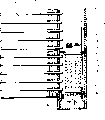
Fig. 1 is the front elevation of cutting open according to the part of the H Exch of the first embodiment of the present invention;
Fig. 2 is partly cut-away's enlarged drawing of the characteristic of H Exch shown in Figure 1;
Fig. 3 is the part sectional view of the characteristic of H Exch according to a second embodiment of the present invention;
Fig. 4 is the part sectional view of characteristic of the H Exch of a third embodiment in accordance with the invention;
Fig. 5 is the part sectional view of characteristic of the H Exch of a fourth embodiment in accordance with the invention; With
Fig. 6 is the front elevation of the improved house steward's of the present invention characteristic.
The specific embodiment
With reference to Fig. 1 and 2, the H Exch according to the first embodiment of the present invention is introduced.
With reference to figure 1, H Exch was a cold mould condenser 1, was the integral type collector type condenser that is used for air conditioner for automobile.Cross cold mould condenser 1 and comprise two house stewards that vertically extend in parallel 2 and 3 and the heat-transfer pipe 4 that is communicated with house steward 2 and 3 of a plurality of extensions parallel to each other.In the introduction below, house steward 3 is called first house steward, and house steward 2 is called second house steward.
Outside face with outmost heat-transfer pipe 4 between each adjacent heat-transfer pipe 4 is provided with many radiating gills 5.Although radiating gill 5 is evenly distributed between house steward 2 and 3 basically, for convenience of explanation, middle radiating gill does not show.
Second house steward 2 is provided with the refrigerant inlet pipe 6 that is connected respectively to the upper and lower and refrigerant outlet pipe 7, the second house stewards' 2 inside is provided with space bar 8.Space bar 8 is divided into upper space and lower space with second house steward's 2 inside.Space bar 8 is divided into first group and second group with heat-transfer pipe 4, and first group forms condensation of refrigerant core 9, and the refrigerant of introducing condenser 1 is carried out condensation; Second group formed cold core portion 10, made condensation of refrigerant core 9 condensed refrigerants cold excessively.Therefore, by form space bar 8 in second house steward 2, whole condenser 1 is divided into condensation of refrigerant core 9 and crosses cold core portion 10.
In condensation of refrigerant core 9, the refrigerant path that the heat-transfer pipe 4 of extension parallel to each other forms can form the known single channel type of prior art.Therefore, introduce each heat-transfer pipe 4 inflow first house stewards 3 of second house steward's 2 refrigerant through inlet pipe 6 by the condensation of refrigerant core 9 of single channel type.After flowing into first house steward 3 downwards, refrigerant directly entered the inlet of cold core portion 10, by crossing each heat-transfer pipe 4 of cold core portion 10, flowed out through outlet pipe 7.Should be pointed out that condensation of refrigerant core 9 can form the known binary channel type of prior art or the refrigerant path of multi-channel type.
With respect to comprising condensation of refrigerant core 9 and crossing the whole cold mould condenser 1 of crossing of cold core portion 10, cross the taking of cold core portion 10 than being about 10%.The experiment test explanation that the inventor carries out takies than preferably between about 5% to about 12%.In above-mentioned scope, can realize best cold ratio excessively, and suppress on high-tension side pressure increase and the motor vehicle fuel cost is descended.Wherein the pressure increase is because at the car engine unit room, promptly in limited condenser size, carries out cold causing in the limited installing space of interior condenser.
To introduce first house steward 3 below.
In first house steward 3, the desiccant unit 14 with hydraulic permeability with the card format setting wherein.Desiccant unit 14 comprises shell 12 and the desiccant 13 that is placed in one.Desiccant unit 14 has a lot of liquid by hole 24.Herein, first house steward 3 forms the plug-in unit holding portion.
With reference to Fig. 1 and 2, first house steward 3 is provided with opening in two axial ends.Particularly, first house steward 3 is at an axial end, and promptly the bottom forms first opening.Cylindrical member 16 can be connected first opening by soldering.First block 17 is threaded onto cylindrical member 16, has sealed first house steward's 3 first opening.It is airtight to guarantee to be provided with sealing member 26 between the inside face of first block 17 and cylindrical member 16.First house steward 3 has at the axial other end, i.e. top, and second opening of formation, second opening is with 18 sealings of second block.
In the mistake cold mould condenser 1 shown in Fig. 1 and 2, desiccant unit 14 resilient mountings are between stay bearing plate 21 and protrusion 19.Therefore, be used for the refrigerating cycle of air conditioner for automobile even cross cold mould condenser 1, and stand strong vibration, but the vibration of the compression of protrusion 19 and distortion absorption dehydration agent unit 14 suppresses or prevented the collision sound of desiccant unit 14.Therefore, can prevent the damage of desiccant unit 14 or noise occurs reliably.
Because the temperature that flows through first house steward's 3 refrigerant changes within a large range, the size of desiccant unit 14 on vertically also can change sometimes.Yet protrusion 19 is that rubber or resin are made, so protrusion 19 can flexibly expand or shrinks according to variation of temperature.Therefore, the collision sound of desiccant unit 14 can be inhibited and prevent in the large-temperature range very much.
Even scale error occurs in the manufacturing process of desiccant unit 14, this error also can be highlighted the elastic expansion of portion 19 or shrink and absorb.Therefore, can improve operability of inserting desiccant unit 14 and the dimensional accuracy of relaxing manufacturing.
Diameter contacts with the lower surface 22 of stay bearing plate 21 greater than the flange 23 of patchhole 20.Therefore, can prevent that refrigerant stream from flowing through the filter screen part 25 of bypass desiccant unit, gap 14 between patchhole 20 and the desiccant unit 14.As a result, effectiveness of regenerator that can improved cold core portion 10, and the single-piece effectiveness of regenerator of crossing cold mould condenser 1.
Because protrusion 19 is to be fixed on first block 17, can prevent to install the reduction with maintenance operation like this.As a kind of selection, protrusion 19 can also be fixed on desiccant unit 14.
With reference to figure 3, introduce H Exch according to a second embodiment of the present invention.Similarly parts are represented with identical mark, and are not further introduced.
H Exch shown in Figure 3 also is the mistake cold mould condenser that is similar to Fig. 1 and 2.Mistake cold mould condenser shown in Figure 3 comprises the elastic telescopic pipe 27 that can flexibly extend and shrink, and it is fixed on first block 27.Telescopic pipe 27 utilizes thrust resilient mounting desiccant unit 14 upwards, therefore can be used as the resilient mounting part.Telescopic pipe 27 can form with elastomeric material, as rubber or resin.
In mistake cold mould condenser shown in Figure 3, desiccant unit 14 flexibly is supported between stay bearing plate 21 and the telescopic pipe 27.Therefore, be used for the refrigerating cycle of air conditioner for automobile and be subjected to severe jolt even cross the cold mould condenser, but the vibration of the compression of telescopic pipe 27 and distortion absorption dehydration agent unit 14, so the collision sound of desiccant unit 14 is prevented or suppresses.Therefore, can prevent reliably that desiccant unit 14 from damaging, or produce noise.
Diameter contacts with the lower surface 22 of stay bearing plate 21 greater than the flange 23 of patchhole 20.Therefore, can prevent the filter screen part 25 of refrigerant stream by the bypass desiccant unit, gap 14 between patchhole 20 and the desiccant unit 14.The result has improved to cross the effectiveness of regenerator of cold core portion 10, crosses cold mould condenser 1 single-piece effectiveness of regenerator thereby improved.
Because telescopic pipe 27 is fixed on first block 17, reduce so can prevent the operability of installing and keeping in repair.As a kind of selection, telescopic pipe can be fixed to desiccant unit 14.
With reference to figure 4, introduce the H Exch of a third embodiment in accordance with the invention.Similarly parts are represented with identical mark, and are not further introduced.
H Exch shown in Figure 4 also is the mistake cold mould condenser that is similar to Fig. 1 and 2.Mistake cold mould condenser shown in Figure 4 comprises elastic O-ring 28, and it generally is known and is fixed to first block 17.O shape circle 28 utilizes its thrust resilient mounting desiccant unit 14 that makes progress, and therefore can be used as the resilient mounting part.O shape circle 28 can form with elastomeric material, as rubber or resin.
Be similar to the mistake cold mould condenser of Fig. 1 and 2 or 3, in mistake cold mould condenser shown in Figure 4, the collision sound of desiccant unit 14 is prevented or suppresses.Because refrigerant stream bypass filter screen part 25 is prevented, therefore, effectiveness of regenerator can improve.
With reference to figure 5, introduce the H Exch of a fourth embodiment in accordance with the invention.Similarly parts are represented with identical mark, and are not further introduced.
H Exch shown in Figure 5 also is the mistake cold mould condenser that is similar to Fig. 1 and 2.In mistake cold mould condenser shown in Figure 5, first opening is formed at first house steward's 3 top and seals with first block 30.Cylindrical member 16 can be connected to first house steward's 3 bottom by soldering.Second block 33 is threaded onto cylindrical member 16, makes first house steward's 3 second closure of openings.Sealing member 26 is arranged between the inside face of second block 33 and cylindrical member 16, forms airtight.
Mistake cold mould condenser shown in Figure 5 comprises the elastic telescopic pipe 32 that can flexibly extend and shrink, and it is fixed on second block 33.Telescopic pipe 32 utilizes downward thrust support desiccant unit 14, therefore can be used as the resilient mounting part.Telescopic pipe 32 can form with elastomeric material, as rubber or resin.
In mistake cold mould condenser shown in Figure 5, the elastic extension of telescopic pipe 32 or contraction have absorbed the vibration of desiccant unit 14, so the collision sound of desiccant unit 14 is prevented or suppresses.If flow through the temperature change of first house steward's 3 refrigerant, desiccant unit 14 size on vertically changes.But the collision sound that the elastic extension of simultaneous telescopic pipe 32 or contraction make desiccant unit 14 is prevented in large-temperature range very or suppresses.Telescopic pipe 32 can be fixed on the desiccant unit 14.
Referring to figs. 1 to 5 introduced each cross in the cold mould condenser, first house steward 3 has the opening that is formed at two axial ends.In addition, the described pipe 34 of Fig. 6 also can be used as house steward.Especially, pipe shown in Figure 6 only has opening on an axial end 34a, and another end 34b seals in advance by drawing or other modes.Pipe 34 comprises plug-in unit, as the desiccant unit, and the opening tegmentum cap closure of an end 34a.Between plug-in unit and block, be provided with the flexibly resilient mounting part of support insert.
Although the present invention is introduced by several embodiment, the those skilled in the art knows that very other modes that the present invention can be different implement.For example, though be described at crossing the cold mould condenser, the present invention also can be used for dissimilar Hs Exch, for example, catcher is arranged near this class H Exch the house steward.
Claims (10)
1. H Exch comprises:
The plug-in unit holding portion that can hold plug-in unit has first opening that forms in described plug-in unit one side;
First block can seal described first opening; With
The resilient mounting part is arranged between described plug-in unit and described first block, but the described plug-in unit of resilient mounting.
2. H Exch according to claim 1 is characterized in that, described plug-in unit holding portion is a pipeline, and described first opening forms at an end of axial described pipeline.
3. H Exch according to claim 2 is characterized in that described pipeline has second opening, and described second opening forms at the axial described pipeline other end; Described H Exch also comprises second block of described second opening of sealing.
4. H Exch according to claim 2 is characterized in that described pipeline has closed end at the axial other end.
5. H Exch according to claim 1, it is characterized in that, described H Exch also comprises the stay bearing plate that is positioned at described plug-in unit holding portion, the insertable patchhole of described plug-in unit, described plug-in unit has the flange that extends in a circumferential direction along outside face, the diameter of described flange is greater than the diameter of described patchhole, and the described plug-in unit of described resilient mounting part resiliency urged makes described flange engage with described stay bearing plate.
6. H Exch according to claim 1 is characterized in that, described resilient mounting is fixed in described first block and the described plug-in unit.
7. H Exch according to claim 1 is characterized in that, described resilient mounting partly has from the outstanding protrusion of one of described block and described plug-in unit.
8. H Exch according to claim 1 is characterized in that described resilient mounting partly comprises telescopic pipe.
9. H Exch according to claim 1 is characterized in that, described resilient mounting partly comprises O shape circle.
10. H Exch according to claim 1 is characterized in that described plug-in unit comprises the desiccant unit, and described unit comprises shell and is contained in the desiccant of described shell.
Applications Claiming Priority (2)
| Application Number | Priority Date | Filing Date | Title |
|---|---|---|---|
| JP2002139807A JP2003336938A (en) | 2002-05-15 | 2002-05-15 | Heat exchanger |
| JP139807/2002 | 2002-05-15 |
Publications (1)
| Publication Number | Publication Date |
|---|---|
| CN1458484A true CN1458484A (en) | 2003-11-26 |
Family
ID=29267790
Family Applications (1)
| Application Number | Title | Priority Date | Filing Date |
|---|---|---|---|
| CN03136405.5A Pending CN1458484A (en) | 2002-05-15 | 2003-05-15 | Head exchanger of insert piece holding part with spring support for insert piece |
Country Status (5)
| Country | Link |
|---|---|
| US (1) | US6935413B2 (en) |
| EP (1) | EP1363086B1 (en) |
| JP (1) | JP2003336938A (en) |
| CN (1) | CN1458484A (en) |
| DE (1) | DE60323901D1 (en) |
Families Citing this family (19)
| Publication number | Priority date | Publication date | Assignee | Title |
|---|---|---|---|---|
| EP1577629A1 (en) * | 2004-03-18 | 2005-09-21 | Behr Lorraine S.A.R.L. | Cap, header and heat exchanger |
| EP1643198A1 (en) * | 2004-09-06 | 2006-04-05 | Behr France Hambach S.A.R.L. | Condenser, in particular for a vehicle cooling system |
| US20060070724A1 (en) * | 2004-10-06 | 2006-04-06 | Visteon Global Technologies, Inc. | Integrated receiver dryer sleeve |
| DE102005005187A1 (en) * | 2005-02-03 | 2006-08-10 | Behr Gmbh & Co. Kg | Condenser for an air conditioning system, in particular a motor vehicle |
| WO2007124484A2 (en) * | 2006-04-21 | 2007-11-01 | Parker-Hannifin Corporation | Integrated cross-flow reservoir |
| JP5732258B2 (en) * | 2010-02-16 | 2015-06-10 | 株式会社ケーヒン・サーマル・テクノロジー | Capacitor |
| JP5488551B2 (en) * | 2010-11-03 | 2014-05-14 | 株式会社デンソー | Receiver and receiver-integrated condenser |
| JP5746872B2 (en) * | 2011-02-01 | 2015-07-08 | 株式会社ケーヒン・サーマル・テクノロジー | Capacitor |
| JP5488575B2 (en) * | 2011-02-22 | 2014-05-14 | 株式会社デンソー | Refrigeration cycle |
| WO2013031837A1 (en) * | 2011-09-02 | 2013-03-07 | サンデン株式会社 | Heat exchanger and heat pump system using same |
| JP5946656B2 (en) * | 2012-03-06 | 2016-07-06 | 株式会社不二工機 | Receiver dryer and manufacturing method thereof |
| KR101936243B1 (en) * | 2012-04-26 | 2019-01-08 | 엘지전자 주식회사 | A heat exchanger |
| JP6039946B2 (en) * | 2012-07-13 | 2016-12-07 | 株式会社ケーヒン・サーマル・テクノロジー | Capacitor |
| JP6119488B2 (en) * | 2013-07-30 | 2017-04-26 | 株式会社デンソー | Receiver and receiver-integrated condenser |
| US20150041414A1 (en) * | 2013-08-09 | 2015-02-12 | Ledwell & Son Enterprises, Inc. | Hydraulic fluid cooler and filter |
| US10094601B2 (en) * | 2016-07-12 | 2018-10-09 | Keihin Thermal Technology Corporation | Condenser |
| JP7114831B2 (en) * | 2019-03-29 | 2022-08-09 | 日軽熱交株式会社 | Receiver tank for heat exchanger |
| DE102020215372A1 (en) * | 2020-12-04 | 2022-06-09 | Mahle International Gmbh | Closing plug for a collector of a refrigerant circuit |
| DE102021201735A1 (en) | 2021-02-24 | 2022-08-25 | Mahle International Gmbh | Collector of a refrigerant circuit |
Family Cites Families (30)
| Publication number | Priority date | Publication date | Assignee | Title |
|---|---|---|---|---|
| US3064819A (en) * | 1959-01-19 | 1962-11-20 | Henry Valve Co | Refrigerant drier |
| DE1601045A1 (en) | 1967-10-14 | 1970-06-11 | Parker Hannifin Corp | Drying device |
| SE417123B (en) * | 1974-06-27 | 1981-02-23 | Walter C Avrea | DEVICE ON A LOCK FOR CONNECTION OF A COOLER'S REFILLING NECK |
| US4272264A (en) * | 1974-08-08 | 1981-06-09 | Multiform Desiccant Products, Inc. | Adsorbent package |
| JPH0616308Y2 (en) | 1989-03-08 | 1994-04-27 | サンデン株式会社 | Heat exchanger |
| US5127466A (en) | 1989-10-06 | 1992-07-07 | Sanden Corporation | Heat exchanger with header bracket and insertable header plate |
| JPH0622018U (en) | 1992-08-27 | 1994-03-22 | サンデン株式会社 | Bracket structure of heat exchanger |
| JPH06129791A (en) | 1992-10-15 | 1994-05-13 | Sanden Corp | Heat exchanger and method for fixing bracket thereof |
| JP3617083B2 (en) | 1993-10-12 | 2005-02-02 | 株式会社デンソー | Receiver integrated refrigerant condenser |
| DE4402927B4 (en) | 1994-02-01 | 2008-02-14 | Behr Gmbh & Co. Kg | Condenser for an air conditioning system of a vehicle |
| JPH07301472A (en) | 1994-05-09 | 1995-11-14 | Matsushita Refrig Co Ltd | Header |
| DE4421834A1 (en) * | 1994-06-22 | 1996-01-04 | Behr Gmbh & Co | Use for a condenser of an air conditioning system of a vehicle |
| JP3393957B2 (en) | 1995-05-30 | 2003-04-07 | サンデン株式会社 | Heat exchanger fluid supply / drain pipe joining method |
| JPH08327281A (en) | 1995-05-30 | 1996-12-13 | Sanden Corp | Header for heat exchanger |
| JP3357511B2 (en) | 1995-08-10 | 2002-12-16 | カルソニックカンセイ株式会社 | Condenser |
| JPH09280780A (en) | 1996-04-15 | 1997-10-31 | Calsonic Corp | Header pipe for heat exchanger |
| JPH10206068A (en) | 1997-01-17 | 1998-08-07 | Sanden Corp | Bracket for heat exchanger |
| JP3912836B2 (en) | 1997-02-21 | 2007-05-09 | サンデン株式会社 | Heat exchanger |
| DE19712714A1 (en) * | 1997-03-26 | 1998-10-01 | Behr Gmbh & Co | Use for a collector profile of a capacitor |
| JPH10290091A (en) | 1997-04-14 | 1998-10-27 | Diamond Electric Mfg Co Ltd | Working method for sealing part in heat pipe |
| WO1999010690A1 (en) | 1997-08-21 | 1999-03-04 | Zexel Corporation | Receiver tank and filter member therefor |
| DE29721546U1 (en) | 1997-12-05 | 1998-01-29 | Controls Gmbh Deutsche | Dryer cartridge for vehicle air conditioning |
| JP3790946B2 (en) | 1997-12-08 | 2006-06-28 | 株式会社ヴァレオサーマルシステムズ | Heat exchanger |
| JP4109764B2 (en) | 1998-09-02 | 2008-07-02 | 昭和電工株式会社 | Subcool system capacitor |
| JP4190668B2 (en) | 1999-07-23 | 2008-12-03 | カルソニックカンセイ株式会社 | Receiver |
| US6360560B1 (en) * | 1999-12-01 | 2002-03-26 | Visteon Global Technologies, Inc. | Condenser with integral receiver dryer |
| US6260379B1 (en) * | 1999-12-01 | 2001-07-17 | Visteon Global Technologies, Inc. | Condenser with integral receiver dryer |
| JP2001263869A (en) | 2000-03-23 | 2001-09-26 | Calsonic Kansei Corp | Liquid tank |
| JP2002267390A (en) | 2001-03-09 | 2002-09-18 | Sanden Corp | Heat exchanger |
| US6622517B1 (en) * | 2002-06-25 | 2003-09-23 | Visteon Global Technologies, Inc. | Condenser assembly having readily varied volumetrics |
-
2002
- 2002-05-15 JP JP2002139807A patent/JP2003336938A/en active Pending
-
2003
- 2003-05-13 US US10/436,105 patent/US6935413B2/en not_active Expired - Lifetime
- 2003-05-14 EP EP03253001A patent/EP1363086B1/en not_active Expired - Lifetime
- 2003-05-14 DE DE60323901T patent/DE60323901D1/en not_active Expired - Lifetime
- 2003-05-15 CN CN03136405.5A patent/CN1458484A/en active Pending
Also Published As
| Publication number | Publication date |
|---|---|
| US6935413B2 (en) | 2005-08-30 |
| EP1363086A1 (en) | 2003-11-19 |
| DE60323901D1 (en) | 2008-11-20 |
| JP2003336938A (en) | 2003-11-28 |
| EP1363086B1 (en) | 2008-10-08 |
| US20030213583A1 (en) | 2003-11-20 |
Similar Documents
| Publication | Publication Date | Title |
|---|---|---|
| CN1458484A (en) | Head exchanger of insert piece holding part with spring support for insert piece | |
| US6349562B1 (en) | Closure for an air conditioner collection vessel | |
| US5992174A (en) | Insert for a collector profile of a condenser | |
| US6742355B2 (en) | Receiver-drier for use in an air conditioning system | |
| US6170287B1 (en) | Desiccant installation for refrigerant condenser with integral receiver | |
| CN1864796A (en) | Filters | |
| CN1670453A (en) | Condenser cartridge, in particular for an air-conditioning unit for vehicles | |
| CN1112225A (en) | Conduit attachment to receiver/drier or accumulator | |
| CN2828677Y (en) | Float-type liquid storage apparatus | |
| CN109974351B (en) | Expansion valve aluminum inlet and outlet pipe assembly for heavy truck automobile air conditioner and processing technology thereof | |
| CN111306381A (en) | Integrated pump gate pipeline automatic coupling device | |
| CN1273785C (en) | Heat exchanger | |
| CN111594741B (en) | Automobile oil pump shell | |
| CN115155261A (en) | A disconnect-type desicator for vehicle air suspension air supply system | |
| US6763679B1 (en) | Standoff for desiccant in condenser reservoir of automotive air conditioning system | |
| CN218306806U (en) | Purifier for air separation | |
| CN211875360U (en) | Integrated pump gate pipeline automatic coupling device | |
| CN101063596A (en) | Plate-fin heat exchanger | |
| US10780389B2 (en) | Magnetic desiccant bag | |
| CN216244681U (en) | Auxiliary cooling device for air-conditioning air-cooled pipeline | |
| US7001440B1 (en) | Fluid filter assembly with a fin array | |
| CN214396719U (en) | Air prefilter for braking system | |
| CN108120123B (en) | Liquid reservoir and refrigerating system with same | |
| CN217686001U (en) | Pipeline structure, refrigerating system and refrigerating equipment | |
| CN215571403U (en) | Drying bottle barrel for refrigeration air conditioning equipment |
Legal Events
| Date | Code | Title | Description |
|---|---|---|---|
| C06 | Publication | ||
| PB01 | Publication | ||
| C10 | Entry into substantive examination | ||
| SE01 | Entry into force of request for substantive examination | ||
| C02 | Deemed withdrawal of patent application after publication (patent law 2001) | ||
| WD01 | Invention patent application deemed withdrawn after publication |