CN1268859C - Method and device for controlling clutch and/or speed variator - Google Patents
Method and device for controlling clutch and/or speed variator Download PDFInfo
- Publication number
- CN1268859C CN1268859C CN 98800731 CN98800731A CN1268859C CN 1268859 C CN1268859 C CN 1268859C CN 98800731 CN98800731 CN 98800731 CN 98800731 A CN98800731 A CN 98800731A CN 1268859 C CN1268859 C CN 1268859C
- Authority
- CN
- China
- Prior art keywords
- operating element
- gear shift
- gear
- shelves
- row
- Prior art date
- Legal status (The legal status is an assumption and is not a legal conclusion. Google has not performed a legal analysis and makes no representation as to the accuracy of the status listed.)
- Expired - Fee Related
Links
Images


Classifications
-
- F—MECHANICAL ENGINEERING; LIGHTING; HEATING; WEAPONS; BLASTING
- F16—ENGINEERING ELEMENTS AND UNITS; GENERAL MEASURES FOR PRODUCING AND MAINTAINING EFFECTIVE FUNCTIONING OF MACHINES OR INSTALLATIONS; THERMAL INSULATION IN GENERAL
- F16H—GEARING
- F16H61/00—Control functions within control units of change-speed- or reversing-gearings for conveying rotary motion ; Control of exclusively fluid gearing, friction gearing, gearings with endless flexible members or other particular types of gearing
- F16H61/26—Generation or transmission of movements for final actuating mechanisms
- F16H61/28—Generation or transmission of movements for final actuating mechanisms with at least one movement of the final actuating mechanism being caused by a non-mechanical force, e.g. power-assisted
- F16H61/32—Electric motors actuators or related electrical control means therefor
-
- F—MECHANICAL ENGINEERING; LIGHTING; HEATING; WEAPONS; BLASTING
- F16—ENGINEERING ELEMENTS AND UNITS; GENERAL MEASURES FOR PRODUCING AND MAINTAINING EFFECTIVE FUNCTIONING OF MACHINES OR INSTALLATIONS; THERMAL INSULATION IN GENERAL
- F16H—GEARING
- F16H61/00—Control functions within control units of change-speed- or reversing-gearings for conveying rotary motion ; Control of exclusively fluid gearing, friction gearing, gearings with endless flexible members or other particular types of gearing
- F16H2061/0075—Control functions within control units of change-speed- or reversing-gearings for conveying rotary motion ; Control of exclusively fluid gearing, friction gearing, gearings with endless flexible members or other particular types of gearing characterised by a particular control method
- F16H2061/0087—Adaptive control, e.g. the control parameters adapted by learning
-
- F—MECHANICAL ENGINEERING; LIGHTING; HEATING; WEAPONS; BLASTING
- F16—ENGINEERING ELEMENTS AND UNITS; GENERAL MEASURES FOR PRODUCING AND MAINTAINING EFFECTIVE FUNCTIONING OF MACHINES OR INSTALLATIONS; THERMAL INSULATION IN GENERAL
- F16H—GEARING
- F16H61/00—Control functions within control units of change-speed- or reversing-gearings for conveying rotary motion ; Control of exclusively fluid gearing, friction gearing, gearings with endless flexible members or other particular types of gearing
- F16H61/24—Providing feel, e.g. to enable selection
- F16H2061/242—Mechanical shift gates or similar guiding means during selection and shifting
-
- F—MECHANICAL ENGINEERING; LIGHTING; HEATING; WEAPONS; BLASTING
- F16—ENGINEERING ELEMENTS AND UNITS; GENERAL MEASURES FOR PRODUCING AND MAINTAINING EFFECTIVE FUNCTIONING OF MACHINES OR INSTALLATIONS; THERMAL INSULATION IN GENERAL
- F16H—GEARING
- F16H61/00—Control functions within control units of change-speed- or reversing-gearings for conveying rotary motion ; Control of exclusively fluid gearing, friction gearing, gearings with endless flexible members or other particular types of gearing
- F16H61/26—Generation or transmission of movements for final actuating mechanisms
- F16H61/28—Generation or transmission of movements for final actuating mechanisms with at least one movement of the final actuating mechanism being caused by a non-mechanical force, e.g. power-assisted
- F16H2061/283—Adjustment or calibration of actuator positions, e.g. neutral position
-
- F—MECHANICAL ENGINEERING; LIGHTING; HEATING; WEAPONS; BLASTING
- F16—ENGINEERING ELEMENTS AND UNITS; GENERAL MEASURES FOR PRODUCING AND MAINTAINING EFFECTIVE FUNCTIONING OF MACHINES OR INSTALLATIONS; THERMAL INSULATION IN GENERAL
- F16H—GEARING
- F16H2342/00—Calibrating
- F16H2342/02—Calibrating shift or range movements
-
- F—MECHANICAL ENGINEERING; LIGHTING; HEATING; WEAPONS; BLASTING
- F16—ENGINEERING ELEMENTS AND UNITS; GENERAL MEASURES FOR PRODUCING AND MAINTAINING EFFECTIVE FUNCTIONING OF MACHINES OR INSTALLATIONS; THERMAL INSULATION IN GENERAL
- F16H—GEARING
- F16H59/00—Control inputs to control units of change-speed-, or reversing-gearings for conveying rotary motion
- F16H59/68—Inputs being a function of gearing status
- F16H59/70—Inputs being a function of gearing status dependent on the ratio established
-
- F—MECHANICAL ENGINEERING; LIGHTING; HEATING; WEAPONS; BLASTING
- F16—ENGINEERING ELEMENTS AND UNITS; GENERAL MEASURES FOR PRODUCING AND MAINTAINING EFFECTIVE FUNCTIONING OF MACHINES OR INSTALLATIONS; THERMAL INSULATION IN GENERAL
- F16H—GEARING
- F16H63/00—Control outputs from the control unit to change-speed- or reversing-gearings for conveying rotary motion or to other devices than the final output mechanism
- F16H63/02—Final output mechanisms therefor; Actuating means for the final output mechanisms
- F16H63/08—Multiple final output mechanisms being moved by a single common final actuating mechanism
- F16H63/20—Multiple final output mechanisms being moved by a single common final actuating mechanism with preselection and subsequent movement of each final output mechanism by movement of the final actuating mechanism in two different ways, e.g. guided by a shift gate
-
- F—MECHANICAL ENGINEERING; LIGHTING; HEATING; WEAPONS; BLASTING
- F16—ENGINEERING ELEMENTS AND UNITS; GENERAL MEASURES FOR PRODUCING AND MAINTAINING EFFECTIVE FUNCTIONING OF MACHINES OR INSTALLATIONS; THERMAL INSULATION IN GENERAL
- F16H—GEARING
- F16H63/00—Control outputs from the control unit to change-speed- or reversing-gearings for conveying rotary motion or to other devices than the final output mechanism
- F16H63/40—Control outputs from the control unit to change-speed- or reversing-gearings for conveying rotary motion or to other devices than the final output mechanism comprising signals other than signals for actuating the final output mechanisms
- F16H63/46—Signals to a clutch outside the gearbox
Abstract
The invention relates to a method and device for controlling clutch and/or speed variator.
Description
Technical field
The present invention relates to a kind of method of characteristic location of operation geometric drawing of speed changer of learning automaton.
The invention still further relates to a kind of device of characteristic location of operation geometric drawing of speed changer of learning automaton.
Background technique
Make the speed changer automation that wherein is provided with a gear-changing component seem more and more important recently,, when one of experience is selected the shelves row, can cross different gear shift shelves row, in these grades row, can realize a gear conversion by described gear-changing component.This automatic transmission is than the low cost of manufacture of epicyclic gearbox, and working efficiency is higher.
For gear shift reliably, essential is that this gear-changing component as far as possible accurately is moved along an operation geometric drawing by actuator.When this operation geometric drawing is stored in the micro-processor controlled presetting apparatus, just can realize fast and gear shift exactly.A problem that occurs in practice is, also is different even this operates geometric drawing accurately in the speed changer of same structure form owing to the reason of manufacturing tolerances.And variation has all taken place in the reason owing to wearing and tearing in the continuity of working time on different positions.
For addressing this problem, a computer assisted method that is used to proofread and correct property (neutral gear) position among the electrodynamic type X-Y gearshift mechanism has been proposed in U.S. Pat-PS5305240, wherein, this gear-changing component can move on the directions X that is used to select gear shift shelves row, can move on the Y direction and fits with the abutment face of a shift block.This gear-changing component is moved to the corresponding abutment face of shift block and fits, and the location recognition that takes place to fit is gone out.Go out a neutrality (neutral gear) position according to the position calculation that reclines on two abutment face of a shift block, wherein, when Motor Vehicle stops, all carry out this neutral position determined that therefore, this neutral position is constantly upgraded at every turn.Characteristics of this known method are that the operation geometric drawing only selects the characteristic location of shelves row to be predicted out and brought in constant renewal in by being positioned at.
Also disclose the method for characteristic location of the operation geometric drawing of a study automatic transmission in US-PS4856360, wherein, in the gear shift shelves were listed as, sync bit can be predicted.
Common is for two listed files, is so to realize to the detection that arrives characteristic location by gear-changing component,, judges the torque of a raising according to the current drain of the motor that is used to operate gear-changing component that is.Additional electric line element is then depended in this current measurement, and as current measurement resistance, lead etc. make that so then the structure collectivity of control gear is complicated.These information that realized by the operation geometric drawing of automatic transmission by described known method only can be described to inaccuracy to operate geometric drawing and only allow to upgrade the data of being stored under a big relatively spacing mode.
Summary of the invention
Task of the present invention is, a kind of method and apparatus of characteristic location of the operation geometric drawing that is used for learning an automatic gearbox is set, this method maybe this device can be brought in constant renewal in ground identifying operation geometric drawing like this, makes gear shift to be implemented rapid, accurate and reliablely.
According to the present invention, a kind of method of characteristic location of operation geometric drawing of the speed changer that is used to learn an automation is proposed, wherein, the operation geometric drawing comprises one and selects shelves row and a plurality of space to be provided with, select the vertical gear shift shelves row of shelves row relatively, gear-changing component portion within it moves, this gear-changing component can moved on by two coordinate directions that constitute along the gear shift direction of selecting grade choice direction of row and be listed as along the gear shift shelves under the control of the presetting apparatus of a study by an actuator, wherein, each is detected motion on this gear-changing component each in two coordinate directions by a sensor, this signal of sensor is transported in the described presetting apparatus as position signal, and, it is identified in this sequencer when this gear-changing component arrives the characteristic location of operation geometric drawing, wherein, in a storage device of this presetting apparatus, respectively corresponding position signal and characteristic location are mapped, wherein, by this presetting apparatus predict out gear-changing component arrive be positioned at select within the shelves row and outside characteristic location, make this operation geometric drawing in storage device, generally be depicted and constantly be updated.
According to the invention requirement, characteristic location is predicted and is stored, and these characteristic location have not only been described selection shelves row but also described gear shift shelves row, and according to this, this operation geometric drawing can totally be documented in the storage device.Accurate identification and its continuous renewal by this operation geometric drawing just can be realized, gearshift procedure can especially promptly be implemented when needed, because can realize a controlled operation and needn't carry out the operation of a forced adjustment for this gearshift procedure itself, wherein, the position of gear-changing component was constantly fed back by position transducer between its moving period.
According to the particularly advantageous mode of execution of the inventive method, between the moving period of gear-changing component, continuous data can be obtained by the operation geometric drawing of speed changer, therefore, carries out continuously on the renewal reality of work.
The present invention gives two method for optimizing schemes that are used to predict the linear property position.
Can realize in simple mode, when the operation beginning or when putting into operation or putting into operation again for the first time, for example in safeguarding occasion, to from storage device, bring into operation by a minimum data array, the numerical value that does not formerly also predict during bringing into operation then is in operation and is predicted, and constantly is updated then.
Define the characteristic location of using with optimal way in addition, they also comprise straight line or crooked lines.
The characteristic location that detects directly can be stored in the storage device or according to the characteristic location that predicts and calculate the mathematics position, then it be stored.
Precision according to the inventive method is so improved, promptly be considered at gear-changing component with elasticity between the member that it engages.
Constantly carry out an absolute compensation of position signal when the evident characteristics position, like this, the speed of operational reliability and automaitc shfit all is enhanced.
Need not measure the electric current of drive motor just can discern by a characteristic location of gear-changing component arrival, wherein, for example can calculate torque, impose voltage thereon and send during the motor movement that causes thus and this torque is a motor according to a motor characteristic curve of in the storage device of presetting apparatus, storing.
The advantage that realizes with a preferred version is can directly know by the information on two coordinate directions when arriving a characteristic location.
During at the Motor Vehicle run duration of a speed changer that automation is housed that is at gear that has inserted and transmitting torque, also can be obtained and can be updated about the information of the operation geometric drawing of speed changer.
According to the present invention, a kind of device that is used for by the characteristic location of the operation geometric drawing of the speed changer of an automation of the inventive method study is also proposed, comprise: a speed changer that has gear-changing component, this gear-changing component can select the shelves row to move with a plurality of vertical with selecting the shelves row respectively gear shift shelves row along one, wherein, this selection grade row and gear shift shelves row all belong to the operation geometric drawing of this speed changer, constitute orthogonal two coordinate directions along the choice direction of these selection shelves row and the gear shift direction that is listed as along these gear shift shelves; A drive unit that is used to make this gear-changing component on a coordinate direction, to move; A position transducer that is used on this coordinate direction, detecting the position of gear-changing component; Other being used for makes the drive unit of gear-changing component motion on another coordinate direction; An other position transducer that is used on another coordinate direction, detecting the position of gear-changing component; With a control gear and a storage device that has the processor unit that is used to implement distinct program, it is used to store corresponding to external control signal program operation, that be used for accessory drive and stores those characteristic location by the operation geometric drawing of the speed changer that output signal derived of position transducer; They are upgraded continuously and are imported the control program that this is used for drive unit, wherein, by this presetting apparatus can predict gear-changing component arrive be positioned at select within the shelves row and outside characteristic location, make this operation geometric drawing in storage device, can generally be depicted and constantly be updated, and, have the characteristic location that at least one is different from the gear shift end position, when arriving this position, the continuation campaign of gear-changing component on two coordinate directions is locked.
The invention still further relates to a kind of method that is used for the zero-compensation of increment type measurement in addition, this increment measurement is to carry out the transmission of movement between executive component to an operating element, and this operating element belongs to the device of change velocity ratio between a driving motor and at least one wheel for motor vehicle.The invention still further relates to a device of implementing said method.
The automation mechanized operation of the speed changer of this Motor Vehicle occupies more and more higher critical role recently.The speed changer of this class automation is all with low cost than the automatic transmission of automatic transmission that has transducer and planetary gear group or stepless work.In addition, the speed changer of automation has than the less frictional loss of corresponding described automatic transmission, and then the fuel consumption of Motor Vehicle is descended.
In the speed changer of this automation, clutch and gear shift operation itself operated by executive component and finished, motor for example, oil hydraulic cylinder etc., wherein, settle an increment transmitter on executive component, it produces a pulse when executive component continues a definite quantity of motion (increment), therefore, the number of pulse can dispose with the position of a clutch operating element and/or gear-change operation element is corresponding.
May take place in practice, single increment loses when counting, and this just causes inaccuracy when determining absolute position.Therefore, momentarily, perhaps when entering definite condition, the reference point of must travelling so that to the absolute position determine proofread and correct or compensate.For this reason, used the zero-compensation derailing switch, it is the closed compensation that also can realize a count value when arriving reference point.This zero-compensation derailing switch means the expense of additional member and wiring etc., so cost has improved.
Task of the present invention is, so improves and develop the method for the described type of beginning, promptly can realize a reliable zero-compensation in simple mode.The further task of the present invention is that a device of implementing said method is provided.
The inventive method does not then require additional zero-compensation derailing switch.This precalculated position can by a screens structure or other cause for the change in resistance of the motion of operating element or also can constitute by a limit structure, the arrival in this precalculated position is only by so discerning, that is the Operational Limits of control instrument assessment executive component and for example depress expansion of consumed current or change the arrival of discerning this precalculated position in same electrical, by a unexpected revolution by motor.
Can realize an accurate especially zero-compensation, because, owing to the inexactness that exists elasticity to cause has been compensated.
The position that should determine limits by a limit structure, rises from here, and this operating element can not be moved.
The present invention also comprises the basic structure of the device of implementing said method.
Give the feature scheme with advantage of apparatus of the present invention.
Can operate a speed changer by operating element.
This operating element can also be set for clutch of operation.
Description of drawings
By the embodiment in the sketch with as other details of embodiment the present invention is given explanation below.
Fig. 1 is the skeleton diagram of the gear-changing component of an automatic transmission of control;
Fig. 2 and 3 is the sectional views that are used to explain other member mating reaction of this gear-changing component and a speed changer;
Figure 4 and 5 are stereograms of two different running statees of speed changer;
Fig. 6 is a stereogram that is used to guide the track slotware of gear-changing component;
Fig. 7 to 12 is schematic representation of explaining the mode of action of a gear shift lock;
Figure 13 to 15 is schematic representation of explaining another gear shift lock embodiment's the mode of action;
Figure 16 to 21 is operation geometric drawing (geometrie) schematic representation of explaining a speed changer of the inventive method;
Figure 22 and 23 is schematic representation of a lower bound gearshift map;
Figure 24 to 27 is the schematic representation that are used to explain processing mode when detecting characteristic location;
Figure 28 to 31 is the operation geometirc illustration intentions with characteristic location; Wherein, when characteristic location arrives, obtain the data of two coordinate directions;
Figure 32 and 33 is used to explain the schematic representation that detects a gear shift end position;
Figure 34 is the characteristic curve of a motor;
Figure 35 is a schematic representation of explaining a gearshift procedure;
Figure 36 and 37 is the flow charts corresponding to the process of Figure 35;
Figure 38 is a device that is used to operate a speed changer or a clutch;
Figure 39 is a skeleton diagram that is used to control the device of Figure 38;
Figure 40 is an increment sensor schematic representation;
Figure 41 is a skeleton diagram that is used to control a motor;
Figure 42 to 45 is various embodiment's schematic representation of cam drive;
Figure 46 and 47 is two embodiments that are used for being arranged on the limit structure of cam drive; With
Figure 48 is a balance flow chart;
Embodiment
According to Fig. 1, the gear-changing component 2 of a speed changer can be swung at the direction moving linearly of double-head arrow W and at axis upper edge double-head arrow S, and wherein, W is used for selecting shelves row (Gasse), and S is used for gear shift.In order to drive above-mentioned straight line motion, be provided with a motor 4, and, a motor 6 be set in order to drive above-mentioned oscillating motion.For motor 4 and 6, be provided with drive circuit 8 and 10, they for example provide voltage pulse with respect to the Metacentre Height of its pulse duration modulation to motor 4 and 6.This drive circuit 8 and 10 are controlled by an electronic control equipment 12, and this instrument 12 has a microprocessor 12a and storage device 12b in known manner and also has interface 12c if necessary, 12d.By them, analog input signal is convertible into digital input signal or makes digital output signal convert analog output signal to.The operation of the motion of gear-changing component 2 or motor 4 and 6 then records by sensor 14 and 16, and this sensor for example can be set to the structure of increment counter and send a pulse when rotating a predetermined angle in that motor is each.This sensor 14 and 16 output signal are transported to control instrument 12, this instrument 12 also obtain at another 18 places, inlet opening about a unshowned Motor Vehicle drive the operating condition signal of motor and according to this gear-changing component 2 of these SC sigmal control so that carry out the shift procedure that determines.
Be appreciated that this control instrument 12 also can be transfused to a large amount of other signals, for example from the signal of the limit switch of unshowned speed changer, and control instrument 12 also can control other construction package, for example a unshowned clutch.
Below, the present invention is described by the structure of known speed changer tout court for further explaining:
Fig. 2 and 3 has shown the sectional view of the basic building block that is used to operate a speed changer:
This gear-changing component 2 is (double-head arrow W) and (double-head arrow S) installation movably rotationally in a housing 20, and at gear shift pawl 22 of its end formation, this gear shift pawl is being movably to be meshed with different range forks and can to move a corresponding range fork 24,26 or 28 linearly when double-head arrow S direction is rotated being used on the direction of double-head arrow W.Other speed changer structure is also arranged, and wherein, for example gear selecting process (selection range fork) is that a swing by gear-changing component causes, and realizes by a linear motion for the range fork operation that inserts a gear.
The linear steering structure of range fork is indicated with 30 and 32.
Fig. 2 has shown that gear-changing component 2 is on the position of its top, and wherein, shelves pawl 22 is limited in the limit structure place on a transmission case side.Fig. 3 has shown that gear-changing component 2 is on its position bottom, wherein, one gear-changing component 2 with gear shift pawl 22 opposite opposed sides on the additional extremity piece 34 that constitutes rest on one with the fixing limit structure 36 of housing on.This label 34 relates to another gear shift pawl that is used for reverse gear, it be limited the border to down stroke by touching on the gear shift fork shaft.
Figure 4 and 5 have shown the schematic isometric of the member among Fig. 2 when different running state.According to Fig. 4, the gear shift pawl 22 of gear-changing component 2 is in its neutrality (neutral gear) position, wherein, it on the direction of selecting motion W be can be free between range fork 24,26 and 28 toward and return motion.
In Fig. 5, this gear shift pawl 22 is in range fork 24 inside and is moved to the left side along gear shift direction according to Fig. 5, and therefore, range fork 24 is moved to the left side equally, and inserts a corresponding gear.On the position of Fig. 5, the selection campaign of this gear shift pawl 22 is by locking because, gear shift pawl 22 when a selection campaign to bottom just with a leg piece of adjacent range fork 26 mutually by putting.Be appreciated that under situation about accurately describing the gear shift campaign of the gear-changing component 2 shown in the circle is convertible into a circus movement of gear shift pawl 22 in Fig. 2.But, under this little oscillating motion and lever ratio situation, this circus movement can be approx two front S by linearity represent.
Embodiment by the described transmission operating of Fig. 2 to 5 causes one of gear shift pawl 22 kinetic characteristic that is essentially H shape sign generally, wherein, so-called to select shelves row (Wahlgasse) or the inner direction along double-head arrow W of neutral (neutral gear) shelves row be movably to gear shift pawl 22 at one, and classifying vertical gear shift shelves row (Schaltgasse) inside at three or more as with respect to these selection shelves movably maybe can swing along the direction of double-head arrow S, simultaneously, with this motion gearshift procedure of always ining succession mutually, therefore, these corresponding shelves row are called gear shift shelves row.This gear shift shelves row are that the movement by range fork 22,24 and 26 is defined as, and are what to be defined as by the limit structure on case of transmission and select the shelves row.
As selection, gear-changing component 2 according to Fig. 6 can be provided with an axle journal 38, and it is embedded in the track slotware 42, its be configured in one with the fixing member 40 of case of transmission in, this track slotware 42 has constituted one and has selected shelves row 44 and gear shift shelves row 46,48 and 50.
Return Fig. 4, just may not take place under the transmission operating situation of track slotware having, this gear shift pawl 22 is not accurately to be positioned on the height of a range fork, therefore, it just may drive two range forks when gear shift direction is moved, this will cause one of speed changer to disturb fault.Therefore, be provided with the locking closure of machinery, it will be explained by Fig. 7 to 15 below.
Fig. 7 has shown a stereogram that has the gear-changing component 2 of gear shift pawl 22 and gear lock 52 and 54; Fig. 8 has shown the sectional view by the structural arrangements of Fig. 7.
As seen, two gear locks 52 and 54 on the gear-changing component 2 that is configured to shift shaft and chosen axis, have been settled, one of them gets off directly to rest on the gear shift pawl 22 from the top, and another comes also directly to rest on the gear shift pawl 22 from bottom, they so embed in the member 56 of a fixed position in that side that deviates from gear shift pawl 22 of gear-changing component 2, make them in choice direction, can move only, but be not movable maybe can not swinging on gear shift direction with gear-changing component 2.In addition, in Fig. 8, also indicated three range forks 24,26 and 28, wherein, in the range fork 26 in the middle of this gear shift pawl 22 is embedded into.
By Fig. 9 to 12, explain function according to the structural arrangements of Fig. 7 and 8.
In Fig. 9, this gear shift pawl 22 is in bottom the range fork 28.The range fork 24 of these two tops and 26 movement are locked by gear lock 52.This gear-changing component or gear shift pawl 22 can move upward in selecting the shelves row.
According to Figure 10, in the range fork 26 that this gear shift pawl mediates.52 and 54 limit movement with range fork 24 and 28 of this gear lock are lived.
According to Figure 11, this gear shift pawl 22 is moved right, and therefore, this range fork 26 is operated so that connect a gear.By gear lock 52 and 54, range fork 24 and 28 motion are by locking.And range fork 24 and 28 has stoped the motion of gear shift pawl 22 in Vertical direction.
According to Figure 12, this gear shift pawl 22 is between range fork 26 and the range fork 28.From this position, moving of range fork can not be taken place, therefore, the gear lock 52 and 54 that moves through of all range forks is lockable.
Figure 13 to 15 has shown the another embodiment of a gear lock device, and it prevents that two gears from being inserted simultaneously.What describe respectively is two range forks 26 and 28, and the gear shift fork shaft 60 and 62 of they and linear leading is for being rigidly connected.Between these two gear shift fork shafts 60 and 62, be equipped with a lock pin 64, it is that size so is set, that is, it fully in the holding grooving 66 and 68 of on gear shift fork shaft 60 and 62, constructing or the holding of part mode in these two flutings.In Figure 14, this range fork 26 and gear shift fork shaft 60 move to the right, and locking rod 64 are got into fully in the grooving 68 of gear shift fork shaft 62.And this lock pin 64 is in the guide structure of a fixed position can linear mobile leading, so it has pinned the mobility of gear shift fork shaft 62.
When two range forks 26 and 28 should be moved simultaneously as described in Figure 15 (power F), then lock pin 64 can not withdraw from two groovings 66 and 68, and therefore, two gear shift fork shafts 60 and 62 motion are all by locking; And then, just can not place two gears simultaneously.When the active force on range fork 24 and 26 was inequality, this locking rod was just got in the grooving of that gear shift fork shaft that bears less load, and such result makes the gear shift fork shaft that bears strong load just can move.
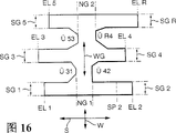
By with the foregoing stroke gauge that is used for gear shift pawl 22 as condition, just can draw one the operation geometric drawing (geometrie), this operation geometric drawing in, this gear shift pawl 22 gear-changing component 2 in other words can move.This operation geometric drawing is often referred to as the gearshift map into H-, and the mode that the line weight in Figure 16 does not wait has been done to describe.Simultaneously only multiple possible gear structural arrangements and a kind of scheme of number of gear setting in Figure 16, wherein, for example this reverse gear can be provided with in addition, promptly can only be 4 gears, perhaps also can 6 gears or the like forward perhaps also can be set more than 5 gears.The characteristic location that plays a decisive role for this motion geometric drawing then is the end position EL and the R (reverse gear) of for example these single gears, 1-5 (shelves level forward), neutrality (neutral gear) shelves row NG2 between gear 5 and R or 3 and 4, neutral shelves row 1 between gear 3 and 4 or 1 and 2, the position and the changeover portion between single gear " " that are used for the gear shift shelves row SG of R and 1-5, for example 4/2 is between the 4th grade and second grade and these synchronous points, and they have all been described in the dot and dash line mode.Synchronous points SP2 refers to, and herein, carries out the synchronous working of second gear.These two neutral shelves row NG1 and NG2 have then constituted together and have selected a shelves row WG.
The geometrical shape of the single part area of this operation geometric drawing can parameter aspect below be different: the width of gear shift shelves row, the position that gear shift shelves row are mutual, spacing between the end position of gear, the width of neutral shelves row, the mutual position of neutral shelves row, the end position of gear is with respect to the position of neutral shelves row, and the size and dimension of the changeover portion between gear shift shelves row and neutral shelves row.When as directed embodiment such, this gear-changing component 2 is operated by two separate executive components or motor, wherein, an executive component control is selected motion W and another executive component control gear shift campaign S, what then meet purpose especially is, these special parameters that are used to describe the geometrical shape aspect of this operation geometric drawing are divided according to their direction.
Characteristic location performed on gear shift direction has been described in Figure 17, for example, the gauge of the end position EL of single gear and neutral shelves row G.At this, they are according to the selected reference point of reasonable manner, this reference point can be positioned at the inside or the outside of operation geometric drawing, but, be maintained fixed, because, the count value of all increment sensors 14 and 16 (Fig. 1) all is based on this reference point, therefore, these count values are respectively corresponding to absolute geometric coordinate, and these coordinates will be reached when each new detection subsequently.Can certainly satisfactoryly select, reference point itself is for example placed on the mid point between NG2/1 and the NG2/2, this mid point just correspondingly is determined and is corresponding with count value 0.
Each described position or characteristic coordinates are all measured, because they have constituted the gauge of the kinetic characteristic that is used for gear-changing component 2, so, corresponding motor just reduces its revolution when arriving a described characteristic location under being subjected to uniform voltage pulse, it is determined in control instrument 12, therefore, the affiliated count value that is provided by sensor 14 or 16 just can store with as the relevant characteristic location that is characterized by position signal.When one of storage is used for the characteristic curve of associated motor in control instrument 12, and the torque that this curve includes correspondent voltage pulse, the revolution that adapts and works, so, this corresponding torque just can be determined, and according to the known position that can occupy when elasticity between the member that it is meshed just can calculate this gear-changing component in no torque conditions at gear-changing component and that.This position signal can correspondingly be corrected, so just to make the state of time spent consistent with gear-changing component 2 unable for the operation geometric drawing of having stored.
Figure 18 has shown that data that record in choice direction select, and wherein, each data is spacing corresponding with of gear-changing component equally.SG characterizes corresponding gear shift shelves row, and this first digital watch that is right after understands that the gear that is access in and second digit mean the left side gauge (1) of these gear shift shelves row on the gear shift direction at corresponding gear in these gear shift shelves row; And the gauge (2) on the right of these gear shift shelves row, according to Figure 18, the upper end of these selection shelves row is represented with WG1, and the lower end is represented with WG2.
Figure 19 shown gear shift shelves row and select the shelves row or neutral shelves row between the transition shelves, wherein, advantageous is that each changeover portion records by three points respectively, between these three points, insert the line of entering, this line is as straight line, arc section, ellipse, parabola, hyperbola also has curvature (perhaps record by more senior multinomial, wherein, need more point for this reason) on a direction or another direction.
Figure 20 has shown a scheme, and promptly how the data that detect according to Figure 17 can be converted, and wherein, according to the data of neutral shelves row gauge, by the formation of mean value, calculates the mean value N2 of neutral shelves row 2 and the mean value N1 of neutral shelves row 1.Then, the whole positional value of these single gear shift shelves row then is referred to the mean value N1 and the N2 of these neutral shelves row by favourable mode.In order to describe neutral shelves row or select the shelves row on gear shift direction, two data have been enough, that is data N1 and data Δ N, and data Δ N provides the spacing between N1 and N2.
Figure 21 has shown that a similar measure is to be used for detecting the conversion of data so that determine center and its border of gear shift shelves row according to Figure 18.Wherein, precondition is that the center that gear shift shelves respect to one another are listed as is always aimed at.
Under the precondition of determining, can be the lower bound gearshift map of a Figure 22 from the mean value sum total of neutral shelves row with the spacing of the mean value of the shelves column position in Figure 20 and 21, explained and end position, this figure is exactly that a simplification of operating geometric drawing is described, and only just indicate its feature by 4 numerical value, that is: the geometric position of central point M, the spacing W of the interval S of gear shift shelves row end position and selection shelves row end position; Wherein, precondition is: M is arranged in selection shelves row and middle gear shift shelves are listed as in the heart; And each gear shift shelves row is that identical length and gear shift shelves row are to aim at mutually.Generally speaking the lower bound gearshift map of Xing Chenging just can be suitable for actual operation geometric drawing in this wise as Figure 23 describes like this, that is, this gear-changing component can move on this lower bound gearshift map under all tolerance situations of covering.Therefore, advantageously, operate the initial value of self study measurement of geometric drawing with this lower bound gearshift map programming and as this during beginning.The operation that is appreciated that a speed changer also can begin according to storage and that know in advance fully operation geometric drawing, and then, this operation geometric drawing is constantly upgraded.
Constantly upgrade and be provided with diverse ways in order to measure this operation geometric drawing and its, they are by the application that is combined of favourable mode:
A) " static state " scanning,
It is static that an executive component or motor are wherein always arranged; And other motor moves, and till gear-changing component runs into a limit structure.
Figure 24 has shown this scanning, wherein, select the motor of the corresponding setting of motion to make gear-changing component 2 move forward a stroke Δ W with one along choice direction at every turn, then, under W kept constant situation, other motor then made gear-changing component move and until arriving limit structure along the gear shift travel direction.
Figure 25 has shown opposite state, wherein, causes the motor of gear shift campaign, make gear-changing component 2 each stroke Δ S of moving, then, another motor makes gear-changing component 2 so continue motion under S keeps constant situation, so that it runs on the limit structure.
B) " dynamically " scanning:
Figure 26 and 27 has shown the possible scheme of dynamic scan, and wherein, two motors that make the gear-changing component motion are simultaneously with high relatively speed operation:
According to Figure 26, this gear-changing component scans the transition region between the 4th grade and the reverse gear, wherein, when moving with the selection that makes progress, carry out a gear shift campaign to the right, therefore, at first the edge on the right of these selection shelves row and the transition region of this inclination then are scanned.In the first portion of this description between moving period, can not move, so just be considered for limit structure although this motor that is used to operate gear-changing component has voltage to apply at first on gear shift direction, wherein, described elasticity as above-cited, just can be calculated.When edge K was crossed then, this motor also just rotated on gear shift direction, and wherein, the torque of raising can be used as the evaluation of layout configurations.
Figure 27 has shown opposite situation, and wherein, gear-changing component is moved to the left side from the position of reverse gear, simultaneously, it in the choice direction by towards below motion, so, it by put along moving direction see reverse gear gear shift shelves row leftmost edge and arrive the edge a transition zone of scanning inclination afterwards.
This gear shift track slotware or gearshift map can on purpose so be revised with respect to nonautomatic corresponding manual gear shifting in an automatic speed changer, and the reference point that promptly is used for the gearshift map measurement is standby at any time.
Figure 28 shows the embodiment of a track slotware (Kulisse) 42 (Fig. 6), wherein, selects shelves row 44 groove 72 that extended to the right, has wherein embedded and gear-changing component 2 rigidly connected axle journals 38.If axle journal 38 arrives in the groove 72, it can not continue to move along choice direction to the right, can not move above or below gear shift direction court.Therefore, this position has constituted a possible scheme that very promptly is used for calibration native system on two coordinate directions.
The embodiment of Figure 29 is consistent with the function of scheme shown in Figure 28, and wherein, holding is in a groove 72 herein with gear-changing component 2 rigidly connected axle journals 38, and this groove 72 is built in the member of a fixed-site.Also described this range fork 24,26 and 28 in addition, gear shift pawl 22 is engaged in them.
In operation geometric drawing according to Figure 30, selecting there are two folding corner regions 74 between shelves row and the gear shift shelves row, it constitutes a limit structure that is used for axle journal 38, wherein, the movement of axle journal on two coordinate directions by locking.Therefore, also form a possibility that detects a reference position rapidly herein.The central position that is appreciated that the selection shelves row that with dashed lines is indicated has a predetermined skew with respect to this reference position.
Embodiment according to Figure 31 is consistent with the function of scheme shown in Figure 30, wherein, reference position is herein locked by a reverse gear and is formed, this reference position operation during gear-changing component by axle journal 38 on request mode travelled, for example when should be at leisure when the 4th gear is transformed into the 5th gear.
Below, describing one by Figure 32 and 33 may scheme, by it, and just can be accurately and a definite gear end position or gear end position reliably:
Described herein is the motor 6 (Fig. 1) that causes the gear shift campaign of gear-changing component 2, and it is connected with change gear structure 80 with synchronizer by not driving parts 78 and a sliding clutch of depicted in greater detail, and gear-changing component 2 also belongs to this driving parts.The rigidity that whole executive component or operation equipment are of course not desirable, but have certain elasticity, it schematically shows by spring 84.This elasticity can be set with the ground of performance data definition arbitrarily by the purpose requirement.By structure 86, its purpose was that a gear can not eject when being subjected to load after change gear structure 80 had one.Be that an end position limit structure 88 has limited the stroke of that unshowned sliding clutch on the opposite direction by structure with this back.
If the supposition, this driving Transmitted chains (Triebstrang) be tensioned and people attempt, take out this gear along direction " neutrality " according to Figure 33 (arrow left).The arrow of Figure 33 has shown equilibrium of forces, wherein refers to:
M: drive Transmitted chains moment
R: action radius
F
N: normal force
M: friction factor
F
HGrenz: be used for the power threshold value that gear takes out.
Be used for power F
HGrenzFormula provide as follows:
Wherein, μ is synchronous friction factor, and α is that the back is by angle (Hinterlegungswinkel).
As long as the power that acts in gear-shifting actuating mechanism is less than power F
HGrenzThe time, then between motor and change gear structure only tensioning the elasticity that exists.
The gear static position can be determined according to following mode now:
Step 1:
In the gear that inserts, approximately produce a known torque M by motor
E, according to this, power F of effect on sliding clutch towards the spacing direction of end position
EIn the elastic range of actuator, little corner of motor operation is until till producing a balance between motor torque and the end position resistance.The corner that records like this is exactly f
E
Step 2:
In inserting gear and drive Transmitted chains and be loaded under the situation of lotus and tensioning, that is be in fully under the Motor Vehicle situation of travelling, producing a moment M by motor
H, this moment acts on a power F towards neutral position orientations on sliding clutch
HAt this, this power must keep below power F described above in the nature of things
HGrenzSo long as this situation, then actuator just is tensioned again, and can record a corner fH in the opposite direction on motor.
Step 3:
Torque M by the motor generation
EAnd M
HCan accurately be pre-determined by drive circuit or Electric Machine Control that output stage limited by one.The elasticity of actuator is known.According to this, residing position in the time of just can detecting actuator and do not stress by simple proportional.This position is corresponding to the gear position of rest of being stored.
Perhaps, this gear static position also can be obtained the torque Zero Crossing Point of motor and determined approx by the voltage signal of analytical calculation current of electric or pulsewidth modulation.
The elasticity of actuator is a system design parameters and according to this, becomes the suction parameter that depends on structure.According to experience, this elasticity can be by the motor torque of analytical calculation the corner of relative motor know.
Perhaps, this gear static position also can be known in such a manner,, can come drive motor with identical torque respectively on both direction that is, then, can average.
Because except synchronous points, this gear static position is the key property position of operation geometric drawing, so be significant especially by Figure 32 and 33 described measures.
Below, summarize those for determining the useful especially characteristic location of operation geometric drawing.In addition, explain tout court, how these characteristic location are determined.At this, cause gear-changing component 2 to select that (Fig. 1) of moving to be called as the selection executive component in the motor 4 and 6, another causes that the motor of gear shift campaign is called as the gear shift executive component.
Measure shift pattern, in choice direction, scan:
During a gear was placed into, this selection executive component moved to along both direction on the limit structure on this grade row border, therefore, shelves column width and at gear 1,2,5 or R in this MAXIMUM SELECTION stroke (WG1 or WG2 are in Figure 18) can be determined simultaneously.The position of Ce Lianging will be verified credibility like this.When gear shift shelves column width when being enough accurately known, measure by selecting executive component only to run in one direction on the limit structure and this position, also just enough, because just can define this grade column position thus.
Measure gear shift shelves column position, on gear shift direction, scan:
If do not have gear to be placed into and clutch is in open mode (for example the driver brakes, starts), this selects executive component to move with step-by-step system in neutral shelves row.After each step, this gear shift executive component moves on gear shift shelves column direction and discerns, and where resistance (seeing Figure 24) occurred.Also can expect such method, it can shorten measuring phase, as bisection method (superposition method at interval).When gear shift shelves column width enough accurately known (fixed value or by measuring in advance), only run in one direction on the limit structure by this selection executive component also just enough because so just define gear shift shelves column position.
During being removed or being placed into, measures gear a gear shift shelves column position:
If gear is removed or is placed into, this selection executive component operation is also discerned this grade row border.
Measure this whole selection stroke:
When not having gear to be placed into, for example the driver brakes or when starting, this selection executive component is carried out this whole selection stroke and discerned these spacing positions.After this, under the control of microprocessor, can carry out a credible check, this credible check is exactly that the summation that the spacing of terminal between spacing and single spacing by storage are formed compares.
Measure neutral shelves column position, in choice direction, scan:
When not having gear to be placed into, the gear shift executive component can move with step-by-step system in gear shift shelves row.This selects executive component after per step, moves and discern this limit structure on neutral shelves column direction.The measuring phase of Suo Duaning also is possible in addition, as bisection method (superposition method at interval).When a neutral shelves column width when being enough accurately known, it is just enough only to measure an edge limit structure.
Measure neutral shelves column position, on gear shift direction, scan:
When not having gear to be placed into, this gear shift pawl can position in the neutral shelves row between two gear shift shelves row.By moving of two side direction on gear shift direction, this gear shift pawl runs into the border of neutral shelves row.If measure two positions in neutral shelves row, the width of so neutral shelves row just can calculate.
Select the conduct of executive component to measure the position of starting point by lower bound gearshift map or known by prior measurement result.Also can use a relative size as starting point for a numerical value that predicts (for example gear shift shelves column position).Select the position of executive component also can step-type method be moved through neutral shelves row.And after each step, this executive component can be determined neutral shelves column position on gear shift direction.When this neutrality shelves column width when being enough accurately known, also just enough in order to determine that an edge limit structure is only measured in its position.
Judge neutral position according to gear end position or gear static position:
Just can come to determine at least approx neutral position according to two opposed gear terminals opposite each other or gear static position by asking intermediate value.This end position also can be applied to a credible check.
Judge neutral position according to sync bit:
This neutral position also can be known according to two opposed sync bits opposite each other.During gearshift procedure, this gear shift executive component just reaches static at synchronous place, perhaps becomes very slow at least.Though this position has error, it also can be by asking intermediate value to be used as the rough orientation of neutral position and determining.
In addition, under the oncoming clutch situation, sync bit can be crossed and therefore can be predicted from neutral shelves row.
Judge neutral position according to screens power (Rastierung):
When speed changer has a gear shift screens structure in neutral (position); The additional load of this gear shift executive component in neutral (position) peripheral region is measured and can identify this position thus.This point only is only possible certainly when low service speed, because screens power is covered up in if not relevant with speed rubbing action meeting.
The measurement of shelves row changeover portion:
Measure changeover portion, the scanning on gear shift direction;
When not having gear to be placed into, this selects executive component to move with step-by-step system in neutral shelves row.After each step, this gear shift executive component moves on the changeover portion direction and can discern a limit structure.This measuring phase can be shortened by bisection method (stack at interval).If need not the substep mode measure this changeover portion, also the possible scheme of Cun Zaiing is, moves to one in advance for selecting the definite position of executive component and rising from here, at the point that detects on the gear shift direction on the changeover portion.This method when the position of changeover portion and shape be the prior feasible especially scheme that is when known.These positions and shape data can be the numerical value of having stored fixed or also can be from measurement result formerly.
In choice direction, measure changeover portion with incremental method:
When not having gear to be placed into, this gear shift executive component can move with step-by-step system in gear shift shelves row.After each step, this selection executive component moves on the changeover portion direction and can discern, and where has run into resistance.This measuring phase can be shortened by the bisection method.Without the step-by-step movement method, also existing the possible scheme of measuring changeover portion is to move to one before for also playing the position of this changeover portion of detection in choice direction on the definite position of gear shift executive component from here.This method also is feasible especially when the position of changeover portion and shape are previously known.These positions and shape data can be the numerical value of fixed storage or also can be from previous measurement result.
The measurement of changeover portion when gear takes out:
During a gear was removed, this selection executive component moved and discerns this grade row border.The position of changeover portion is to be discerned according to the situation that motor quickens by the selection executive component that is under the load relatively.Therefore this position is identified or is known by inverse by systematic parameter.And can also determine the shape of changeover portion according to the velocity curve of selecting executive component.
Changeover portion as given data:
Practice shows, after actuator assembling, does not need the measurement of changeover portion, because this moment, these changeover portions are in size, shape and with the relative position of definite position on be determined.But this method is normally coarse, because these changeover portions have sum of errors wearing and tearing.
Scanning in gear shift direction and choice direction:
Foregoing method can move applied in any combination simultaneously by making two reactors.
The measurement of gear end position:
The front illustrates.
Absolute compensation:
Position that all limit previously and method can be applied to the absolute compensation of the increment sensor of motor or executive component.Wherein, when check of being in operation, determine a reality and deviation previously stored absolute value, and then, correspondingly proofreaied and correct momentary value.
Be appreciated that and replace using motor can also use fluid pressure drive device; And stroke sensor also can be placed near the speed changer or, in speed changer or the limit structure that is provided with in the track slotware can form and directly electrically contact, its pulse signal is fed to control instrument.
Figure 34 shows the characteristic curve schematic representation of motor 4 among a Fig. 1 or 6.PW represents to flow to the pulse width of the voltage signal of motor.η represents the revolution of motor, and it can be obtained by sensor 14 or 16 signals of deriving; N
1To N
NThe expression torque, by it, motor is loaded.Such characteristic curve can be stored in the storage device of control instrument 12 and be used for each motor.
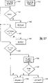
Explain a process by accompanying drawing 35 below, wherein as far as possible promptly from the 5th gear tieback to the 4 gears.This situation is necessary for unexpected overtaking other vehicles for example, when this overtaking process finishes, just can receive the 5th gear from 4 grades at leisure then.One about should be how promptly or how to be derived by vehicle information in control instrument 12 by the signal of gear shift lentamente, for example operate the speed of gas pedal, engine revolution, motor vehicle speed or the like.
This rapid tieback from 5 grades to 4 grades is realized by 4 trip segment, that is trip segment A-B, trip segment B-C, trip segment C-D and trip segment D-E.The control diagram of this tieback will make an explanation by Figure 36 below.
Suppose that send " rapidly tieback " information from 5 grades to 4 grades here from control instrument, then, in block 100, the voltage signal PW1a that has modulated pulse width is transported to motor S (gear shifting motor), wherein, the direction of motor rotation that 1 expression is wished; A is used for the numerical value of pulse width.In block 102, voltage pulse PW1b is transported to simultaneously motor W (be used to motor that gear-changing component is moved) in choice direction.The ratio of this pulse PW1a and PW1b is so selected, and promptly gear-changing component can promptly move towards B along direction A.When predicting according to the sensor signal that belongs to gear shifting motor S in block 104, during in-position 0, then motor S is disconnected in block 106 on gear shift direction.In block 108, determine, whether in-position SG51 (seeing Figure 18) for selection motor W.If this situation, the service voltage of selecting motor is strengthened, in order that gear-changing component can be promptly moved to C by B from the center line (for example constituent element of lower bound gearshift map) of blank.At a B is not to need the check of correlation utterly because the outage of gear shifting motor (block 106) be because in esse error can not be affirmed accurately carries out constantly at this, promptly by select that motor arrives coordinate SG51 that constantly.
When determining that in block 112 when having arrived coordinate SG41 by the selection motor, then two motors are provided with the voltage pulse that is mutually related in block 114,116, in order that this gear-changing component moves along straight line C-D.When determining that in step 116a synchronous points SP4 is arrived, then in step 118, make and select motor W to disconnect, like this, the coordinate of Xiang Guan gear-changing component has just no longer changed therewith.The arrival of this synchronous points SP4 can be determined in a different manner.For example this synchronous points can be stored by corresponding coordinate on gear shift direction.It also can so be identified, that is, descend or the electric current that is received by gear shifting motor is improved by the revolution that makes gear shifting motor S and discern.Then, when in block 120, determining, when the gear shift end position EL4 of the 4th gear has arrived, motor S is disconnected.In this way, carry out one promptly from the gear shift of the 5th gear to the 4 gears.
Explained later is once from 4 grades to 5 grades high gearshift procedure.This process can be carried out at leisure according to the analysis of operating parameter in control instrument 12 and Motor Vehicle parameter.
In block 140, selecting to apply pulse PW2f on the motor, and be provided with voltage pulse PW2g in block 142, for simultaneously gear shifting motor S.This 2 expression, from this moment, turning to of motor is reversed.This gear-changing component moves along the F direction from E.
This moment is when determining that in block 144 motor torque N is higher than a definite torque N
S1(coming the evaluation of properties curve) according to Figure 34, perhaps determine, the motor revolution is lowered by on the null value, perhaps determine, the current drain of motor be strong increase the time, then can make following judge like this, that is, gear shift shelves row border SG41 has arrived and the storing value of relevant coordinate is updated in block 146.
This gear-changing component on gear shift shelves row border by being moved to G from F by gear shifting motor S with putting.At the G place, the torque of this motor W descends suddenly.When being in, motor torque N is lower than value N
S1But be higher than another predetermined value N
S2And when the revolution of motor W is higher than a predetermined revolution N1, then can be passed judgment on as followsly like this, this gear-changing component just moves along changeover portion 4R.This changeover portion 4R is updated in block 150.
When point of arrival H, the torque of motor W drops to suddenly and is lower than a predetermined value N
S3And revolution rises to and is higher than a predetermined value N2.This point is passed judgment on as follows in 154 sections of programs, and this H arrives; According to this, in block 154, import the voltage pulse that is used for counterturn to gear shifting motor S, like this, this gear-changing component travels towards an edge NG22 who selects the shelves row.When the load torque of determining this selections motor M in block 156 when being zero greater than a predetermined value M4 and revolution, this situation just is judged as by having put on the edge NG22; Therefore, in block 158, corresponding coordinate can be updated and in block 160 this gear shifting motor S be disconnected.
Be appreciated that at every turn before upgrading, also can in a subroutine, implement one as the elastic compensating calculating explained in front for the coordinate that rests on the border by gear-changing component to be predicted.
Arrive this, the description of this flow chart just is through with, because it is similar for the description of other gearshift procedure.This gearshift procedure moves to K from I, wherein, is selecting to be used to reclosing of gear shifting motor by putting on the shelves row border WG1; And when a neutral shelves row border NG21 arrives, select motor to be diverted control, arrived until the central authorities of gear shift shelves row SG5R; On this basis, be implemented into the conversion operations of end position EL5 by synchronous points SP5.All numerical value of mentioning can be updated during gearshift procedure.
Can draw according to noted earlier, can realize by the present invention, under the needs situation, can implement gear-change operation especially rapidly, these operations are owing to the accurate understanding to the operation geometric drawing becomes possibility, and simultaneously,, all can do to detect again continuously and upgrade to the operation geometric drawing during the gear shift slowly and/or during gear-changing component 2 is not to be activated for gear shift, can also, in the indeterminedness of credibility check, identify defective.
According to Figure 38, the gear shift pawl 202 of a speed changer of not describing can move on two orthogonal directions in known manner, and wherein, the motion on double-head arrow W direction causes a selection course; Motion on double-head arrow S direction causes a gearshift procedure.
Simultaneously, select motion and gear shift campaign to be determined so mutually, that is, can produce the operation geometric drawing of two-H-shape.
In known manner, this gear shift pawl 202 and gear shift and chosen axis 204 rigidly connected connecing, it is to be placed movably and swingably on axially.
For this 204 or of gear shift pawl 202 move axially axially movable parts 206 be set, it is provided with a groove in its bottom side, in this groove, so set gear shift pawl 202, promptly this gear shift pawl 202 can be swung with respect to parts 206, but axle 204 axially on carried synchronously by parts 206.For a swing, arm spare 208 and axle 204 are for rotatable but be connected movably in the axial direction each other; This arm spare 208 has the groove that is open upwards mouth, the axle journal 210 of parts 212 of holding in groove, and 212 is axially movable on these parts.According to this, one of parts 212 moves axially a gear shift campaign that can cause gear shift pawl 202; And of parts 206 moves axially and can cause to select a motion.For parts 206 and 212 one moves axially an operation equipment 214 is set, it has the drive unit 216 and 218 of two similar structure.
Each drive unit have one as the motor 220 or 220 of executive component ', this motor by worm gears 222 or 222 ' with crank 228 or 228 ' link to each other, worm gears comprise worm screw 224 or 224 ' and worm gear 226 or 226 ', member 230 or 230 by linear guide of crank 228 or 228 ' again ', it for example is the end that hydraulic pressure sends cylinder or flexible axle, links to each other with parts 206 and 212.For auxiliary this drive unit 216 and 218 can make up be provided with power storage 232 and 232 '.This worm gears 222,222 ' rotation can be by increment sensor 234,234 ' detected, this worm gears by velocity ratio and parts 230,230 ' or the linear motion of parts 206 and 212 be in fixing relation, and sensor 234,234 ' when rotating a predetermined corner amount, worm screw 224,224 ' at every turn just sends an output pulse, and it can be treated for the detection of rotation.
A clutch has been described in upper right in Figure 38, and it has a withdrawal fork 242 and a release bearing 244 in known manner.Be provided with an operating element 246 in order to swing withdrawal fork 242, it for example drives by a drive unit with drive unit 216 and 218 similar structures.
Figure 39 shows a frame circuit diagram that is used for the total configuration:
Each motor 220 is connected with a control instrument 252 by an output stage 250, and this control instrument has the microprocessor 254 of the working storage of a band in being integrated in, and storage 256 and input/output interface 258.This control instrument has a plurality of inlet openings 260, also is connected to incremental transducer 234 on it.
The gear shift pawl by motor 220 and according to the structural arrangements of Figure 38 select and gear shift direction on can move.
Figure 40 shows an embodiment who is used for an incremental transducer 234.Be connected an inductor 264 with the live axle 262 anti-rotations ground of this motor, it is equipped with the magnetic pole of handing over Transitional Polar on its excircle.From for example coil part 266 other moving past, each motion provides a voltage pulse to this element 266 to these magnetic poles on the out-of-date just joint 268 at this element on its side when a magnetic pole when inductor 264 rotates.Be appreciated that the embodiment that also exists different increment sensors, for example with reed switch work, with optics work, photo-electron work or the like.
Figure 41 has shown that schematically the circuit of a terminating stage 250 is used to control a motor 220.Four triodes 270,272,274 so are connected with motor 220 in a bridge circuit with 276, that is, motor 220 is on the different direction of voltage source 278 according to the on off state of the triode of controlled instrument 252 controls; Perhaps, motor disconnects mutually with voltage source, according to this, by control instrument 252, makes the turning to of motor 220, and for example by the pulse duration modulation to the voltage pulse that flows to motor 220, also makes the voltage of motor 220 supply with and is all controlled.Just can detect electric current and its flow direction by motor 220 by a current measurement resistance 280.
Figure 42 to 45 has shown the embodiment of different cam gears, its can substitute shown in Figure 38, transmit the worm gears 222 that uses and be employed in the motion of the operating element that is used for described transmission device or clutch from motor 220 to.
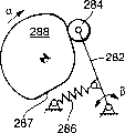
In the embodiment of Figure 42, a roller 284 that is placed on one of lever 282 end is kept resting on the cam curve 287 of a rotatable cam disk 288 that settle and that be driven in rotation by a spring 286, and lever 282 is hinged on its other end.Between the corner β of the corner α of cam disk 288 and lever 282, there is a predetermined relation.
In the embodiment of Figure 43, lever 282 replaces by the tappet 290 of a removable leading, therefore, has a predetermined relation between the displacement S of the corner α of cam disk 288 and tappet 290.
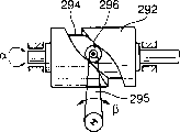
In the embodiment of Figure 44, a rotatable cylinder 292 of settling has a curvilinear groove 294, has wherein set roller 296, and this roller is positioned on the end of lever 295; And settle for rotatable the other end of lever.Between the corner β of the corner α of cylinder 292 and lever 295, there is a predetermined relation.
Set a roller 296 in the embodiment of Figure 45 in curvilinear groove 294, it is positioned on the axle journal 298, and axle journal 298 is configured in again on the slide bar 300 rigidly.Between the corner α of the displacement S of slide bar 300 and cylinder 292, there is a predetermined relation.
Figure 46 has schematically shown the structural arrangements of Figure 44, and wherein, the surface of cylinder 292 has been unfolded, and therefore, curvilinear groove 294 can be described as shown in figure 46.When if described roller arrives spacing A2 of the terminal corresponding left side or the right or A1, then cylinder 292 and lever 295 just can not further move.When lever 295 for example is arm spare shown in Figure 38 208, then just can operate the gear shift of a speed changer by lever 295, wherein, with different end position corresponding the conversion of different gears.According to this,, just can define reliable reference value, on this basis, the counter of the signal of this increment sensor of metering can be set when arriving limit structure that is the state of rest at executive component by arriving limit structure.
What the embodiment of Figure 47 and Figure 46 was corresponding but different is, limit structure A1 and A2 are made of a curvilinear groove, but constitute by curve cam 287, curve cam 287 so be shaped and so with the hinged coordination mutually of levers 282, promptly at limit structure A
1And A
2Self-locking structure of middle formation.
Be appreciated that, this limit structure also can so constitute, promptly cam disk when running to two end position, push up on the axle journal 297 of a fixed-site that is provided with as limit structure (dotted line is represented) or in addition mode can constitute by the mechanical position limitation structure of fixed-site.
An advantage of Figure 46 and 47 the embodiment that can retrofit by many modes is, do not need independent limit structure, but this limit structure can directly form by being in intermeshing component limit, wherein, curve cam both can be defined, and perhaps also can produce a self-locking structure.
The rotation of drive motor 220 (Figure 38) can directly be predicted by increment counter 234, and between how much motions of drive motor 220 and the gear shift pawl 202 that plays a decisive role for the operation of speed changer, all existing elasticity mostly, this elasticity then causes taking place the correspondence configuration of a mistake between the count value of the position of gear-changing component 202 and increment counter 234.Therefore, for the count value for the position correspondence of gear shift pawl 202 when arriving a limit structure has an accurate compensation, then need above-mentioned elasticity is taken in.
Suppose that gear shift pawl or member move a stroke Δ S also changes delta N correspondingly of count value so facing to a limit structure, then:
ΔN=ΔS/i (1)
Wherein, i is an increment of motion, and it makes count value change 1.
Supposition more now, the elasticity in the transmission of movement between the position at the measured place of increment counter and the member that moves on a limit structure is counted:
ΔSe=F×Ce (2)
Wherein, Δ Se is that it can directly be predicted by incremental transducer by the displacement of the input element of executive component operation.
F makes the power of a member towards the limit structure operation, and Ce is the elasticity in the transmission of movement.
This power F is present in the transmission of movement of the member from executive component to position-limiting action, and it can be detected in a different manner:
For example, just can read motor torque and read described power thus or also can measure by a motor characteristic curve (for example state of rest) of being stored and also calculate this torque thus by the mobile electric current of motor according to the revolution of the voltage of motor load and motor.
Draw according to (2) and (1):
ΔNe=F×Ce/i (3)
The count value of reading under the situation that is at member on the limit structure and is loaded by power F is N
1The time, this is worth N
1Must therefore proofread and correct, so that obtain the reference value N of correction with respect to value Δ Ne
0, this reference value is corresponding to not being loaded at limit structure that is rolling counters forward value when not having transmitting movement effectively.
Be appreciated that this reference value also can so select, promptly, this transmission of movement is in when it upgrades under the predetermined power effect, and wherein, the ratio of actual loaded power and predetermined force can be converted herein, perhaps motor is so controlled, promptly is corrected on the predetermined active force.
Another may scheme be, define a reference value that has nothing to do with power, for example, and two limit structure A
1And A
2By with identical, but the torque of adverse effect crosses, and the average counter value is restricted to reference value.
Explain renewal or a zero-compensation of a reference value below by the flow chart of Figure 48:
Suppose, control instrument 252, know a shift command by the service data of Motor Vehicle, then, in step 300, the modulated voltage signal of pulse width is sent to motor 220 and goes, and the revolution that this motor is then proofreaied and correct with the predetermined pulse width of a basis moves and described transmission of movement element is moved.In step 302, check continuously, whether the count value N's that this directly is associated with the motor revolution is to be positioned at a threshold value a over time
sUnder the limit.If not this situation, so, motor continues to be provided with voltage pulse.In case be this situation, count value N then
1In step 304, be read in the storage 256, because, this threshold value a
sThe value that do not surmount be positioned at very near on zero the level, and as the judgement that arrives a limit structure, so N
1A reference value has been described.This moment is in step 306, but with regard to force calculation F, this power is applied by motor in transmission of movement, and wherein for example, this current of electric is predicted and according to voltage, electric current and motor characteristic calculate motor torque, or is known by the characteristic curve of a storage; Then, detected active force calculates reference value correction value delta Ne in the time of according to the elasticity of known transmission of movement and thus, then, and a value N
1-Δ Ne just is stored as new reference value.Again, motor is disconnected in step 308, because confirm, this gear shift end position has arrived.
The countless remodeling that is appreciated that this method is feasible.For example, this reference value also can so form, i.e. the torque of motor is to descend when a screens structure or a synchronous points are crossed instantaneously that increase or instantaneously.
Determining of this reference value by a limit structure, especially when this limit structure by a self-locking structure when Figure 47 or Figure 46, constituting, be particularly advantageous because, trend towards state of rest at this motor, that is its torque can be detected especially reliably; And, but the geometric position of this limit structure also is defined to monodrome.The reference value that is appreciated that this corrected value or corresponding correction just can have been checked credibility, thereby abnormal skew can be evaluated as fault or the damage in the system.
The method of the characteristic location of an operation geometric drawing that is used for learning (lernen) automatic transmission, wherein, this operation geometric drawing comprises one and selects that settle shelves row and a plurality of space and be listed as with respect to gear shift shelves of selecting shelves row approximate vertical, gear-changing component of portion is transportable within it, this gear-changing component can be moved on two coordinate directions under the presetting apparatus control of a study by an actuator, wherein, all each is detected by a sensor on each direction of two coordinate directions in the motion of operating element, this signal of sensor is transported in the described presetting apparatus and in this presetting apparatus as position signal and is identified, as long as this moment, operating element arrives the characteristic location of operation geometric drawing, wherein, in a storage device of this presetting apparatus, the corresponding corresponding configuration with this characteristic location of position signal is characterized in that:
Detect by this gear-changing component to selecting within the shelves row and the arrival of the characteristic location of outer installment by this presetting apparatus; In order that this operation geometric drawing can generally be depicted in storage device and is updated continuously.
The method that is used for the zero balancing of an increment type measurement, described increment type measurement is in the transmission of movement of the operating element of the device of an executive component to a change velocity ratio, described velocity ratio is the velocity ratio between a driving motor and at least one vehicle wheels, wherein, transmission of movement between executive component and operating element detects by an incremental transducer, signal of sensor is counted and is transported in the control gear that is provided with storage device, and be used for the operation of control actuating component, wherein, a preposition of operating element is corresponding to a stored reference value in storage device, and this method comprises following step:
The operation executive component arrives on the precalculated position of discerning by the change of the Operational Limits of executive component predetermined in control gear up to this operating element, reads with the corresponding count status in this precalculated position and stores this count status as new reference value.
The applicant keeps further, to so far only in explanation and/or in the accompanying drawing disclosed feature make claimed right.
The further modification in construction that the present invention did also constitutes independently invention.
The present invention is not confined on the embodiment of specification.Opposite is to realize countless variants and modifications schemes within the scope of the invention, particularly each flexible program, each element and various combination and/or material for example by with specification in and feature, element or the method step described among the embodiment and comprise in the accompanying drawings make up mutually and creative, and, can form a new technological scheme or form new method step or series of method steps by feature capable of being combined, and they also relate to manufacturing, the content of check and method of work etc.
Claims (38)
1, be used to learn the method for characteristic location of operation geometric drawing of the speed changer of an automation, wherein, the operation geometric drawing comprises one and selects shelves row and a plurality of space to be provided with, select the vertical gear shift shelves row of shelves row relatively, operating element portion within it moves, this operating element can moved on by two coordinate directions that constitute along the gear shift direction of selecting grade choice direction of row and be listed as along the gear shift shelves under the control of the presetting apparatus of a study by an actuator, wherein, each is detected motion on this operating element each in two coordinate directions by a sensor, this signal of sensor is transported in the described presetting apparatus as position signal, and, it is identified in this presetting apparatus when this operating element arrives the characteristic location of operation geometric drawing, wherein, in a storage device of this presetting apparatus, respectively corresponding position signal and characteristic location are mapped, it is characterized in that:
By this presetting apparatus predict out operating element arrive be positioned at select within the shelves row and outside characteristic location, make this operation geometric drawing in storage device, generally be depicted and constantly be updated.
2,, it is characterized in that by the described method of claim 1: at this operating element along the longitudinal edge that predicts out selection shelves row in the choice direction between moving period with selecting transition region between shelves row longitudinal edge and the gear shift shelves row longitudinal edge.
3,, it is characterized in that by the described method of claim 1: at this operating element along the longitudinal edge that predicts out selection shelves row in the choice direction between moving period or selecting transition region between shelves row longitudinal edge and the gear shift shelves row longitudinal edge.
4, by claim 1 or 2 described methods, it is characterized in that: the longitudinal edge and the transition region between gear shift shelves row longitudinal edge and selection shelves row longitudinal edge that predict out corresponding gear shift shelves row at this operating element along gear shift direction between moving period.
5, by claim 1 or 2 described methods, it is characterized in that: the longitudinal edge or the transition region between gear shift shelves row longitudinal edge and selection shelves row longitudinal edge that predict out corresponding gear shift shelves row at this operating element along gear shift direction between moving period.
6, by the described method of claim 1, it is characterized in that: this operating element is moved by step-by-step system with predetermined step width on a coordinate direction therein; After an EOS, this operating element is moved on corresponding another coordinate direction and until arriving a characteristic location.
7, by the described method of claim 1, it is characterized in that: this operating element is driven simultaneously towards a characteristic location on described two coordinate directions and is moved.
8, by the described method of claim 1, it is characterized in that: lower bound gearshift map of storage in described storage device, it comprises a center line selecting the shelves row and a center line of gear shift shelves row.
9, by the described method of claim 8, it is characterized in that: described lower bound gearshift map is activated before putting into operation for the first time or putting into operation again or in the scope of emergency measure.
10, by the described method of claim 1, it is characterized in that: as characteristic location, the end of gear shift shelves row is predicted.
11, by the described method of claim 1, it is characterized in that: as characteristic location, the opposite vertical edge of gear shift shelves row is predicted.
12, by the described method of claim 1, it is characterized in that: as characteristic location, the opposite vertical edge of these selection shelves row is predicted.
13, by the described method of claim 1, it is characterized in that: as characteristic location, the synchronous points of gear shift is predicted.
14, by the described method of claim 1, it is characterized in that: according to the characteristic location that predicts, calculate the position of mathematics, it is stored in the described storage device.
15, by the described method of claim 14, it is characterized in that: according to the characteristic location that is predicted, and be under the flexible condition of the member in engaging at the steering force of having considered operating element with it, calculate the corresponding characteristic position, operating element position when not having steering force.
16, by the described method of claim 1, it is characterized in that: the position signal the when characteristic location that is predicted or calculate is applied to the increment stroke measurment definitely compensates.
17, by the described method of claim 1, it is characterized in that: the arrival of this operating element on a characteristic location, change by a relation and to discern, this relation refers to the relation between the motion output of the power consumpiton of a drive motor that is used for moving this operating element and this drive motor.
18, by the described method of claim 1, it is characterized in that: this operating element changes in the power consumpiton of a drive motor and the relation between the power output by one to the arrival of a characteristic location to be discerned.
19, by the described method of claim 1, it is characterized in that: this operating element is moved to a characteristic location by actuator, and in this position, its continuation campaign on described two coordinate directions all is prevented from.
20, by the described method of claim 1, it is characterized in that: this operating element is moved to a characteristic location by described actuator, and wherein, it is prevented from continuing motion in one direction; And its motion is in the opposite direction only just carried out when surmounting definite in the opposite direction a steering force; According to known at operating element with on this characteristic location and the position of the elasticity between the member of operating element engagement and the operation half way that on this operating element, works operating element when calculating no steering force in advance; This position is rated as the position of operation geometric drawing characteristic location.
21, by the described method of claim 2, it is characterized in that: this actuator comprises that one is selected executive component and a gear shift executive component.
22, by the described method of claim 21, it is characterized in that: when gear is placed into and in end position when unloaded, this selections executive component predicts the longitudinal edge that the gear shift shelves are listed as.
23, by the described method of claim 1, wherein, zero-compensation is made in an increment type measurement, this increment type is measured to be used for changing in a transmission of movement that drives the operating element of the device of velocity ratio between motor and at least one wheel for motor vehicle by executive component at one and is carried out, wherein the transmission of movement between executive component and operating element detects by an increment sensor, the output signal of this increment sensor is counted and is transported in the control gear that is provided with storage device to be used for the operation of control actuating component, wherein, a precalculated position of operating element comprises following step corresponding to a stored reference value in storage device:
The operation executive component arrives a precalculated position of knowing by the predetermined change of the Operational Limits of executive component up to operating element in control gear; Read with the count value of this precalculated position correspondence and store this count value as new reference value.
24, by the described method of claim 23, it is characterized in that: this increment sensor directly predicts the position of executive component, when arriving preposition, active force is predicted, power according to this, and this executive component acts on the operating element, calculate the numerical value of increment according to this power and the elastometer between executive component and operating element, based on this numerical value,, must proofread and correct count value corresponding to the precalculated position for a predetermined active force between executive component and operating element; Then, count the counts corrected value, and the count value of storing these corrections is as new reference value with respect to described increment.
25, by claim 23 or 24 described methods, it is characterized in that: described preposition limits by a limit structure.
26, be used to learn the device of characteristic location of operation geometric drawing of the speed changer of an automation, comprise: a speed changer that has operating element, this operating element can select the shelves row to move with a plurality of vertical with selecting the shelves row respectively gear shift shelves row along one, wherein, this selection grade row and gear shift shelves row all belong to the operation geometric drawing of this speed changer, constitute orthogonal two coordinate directions along the choice direction of these selection shelves row and the gear shift direction that is listed as along these gear shift shelves; A drive unit that is used to make this operating element on a coordinate direction, to move; A position transducer that is used for the position of detecting operation element on this coordinate direction; Other being used for makes the drive unit of operating element motion on another coordinate direction; An other position transducer that is used for the position of detecting operation element on another coordinate direction; With a control gear and a storage device that has the processor unit that is used to implement distinct program, it is used to store corresponding to the external control signal operation, program and those characteristic location of storage of being used for accessory drive by the operation geometric drawing of the speed changer that output signal derived of position transducer, these characteristic location are upgraded continuously and are imported the control program that this is used for drive unit, it is characterized in that: by this presetting apparatus can predict operating element arrive be positioned at select within the shelves row and outside characteristic location, make this operation geometric drawing in storage device, can generally be depicted and constantly be updated, and, has the characteristic location that at least one is different from the gear shift end position, when arriving this position, the continuation campaign of operating element on two coordinate directions is by locking.
27, by the described device of claim 26, it is characterized in that: in the described characteristic location one is positioned on the elongation line of the center line of selecting the shelves row.
28, by the described device of claim 26, it is characterized in that: one in the described characteristic location by constituting at these selection shelves row and an outer boundary that only is listed as between the gear shift shelves row of drawing from these selection shelves in a side.
29, by the described device of claim 26, it is characterized in that: a reverse gear locking by a machinery in the described characteristic location forms.
30, by the described device of claim 26, wherein, zero-compensation is made in an increment type measurement, this increment type is measured to be used for changing in a transmission of movement that drives the operating element of the device of velocity ratio between motor and at least one wheel for motor vehicle by executive component at one and is carried out, comprise: an executive component that is used for moving an operating element, this operating element belong to a device that is used to change the velocity ratio between a driving motor and at least one wheel for motor vehicle; Increment sensor in transmission of movement between executive component and operating element; A control instrument that comprises the microprocessor of being with storage device, the output signal that is transfused to increment sensor in this control instrument is to be used to be converted to position information; For control actuating component, also comprise a limit structure, in its transmission of movement between executive component and operating element, but the continuation campaign of its locking executive component, wherein, the arrival of this limit structure is predicted by the change of the Operational Limits of executive component in control gear, and this relevant position information is used as reference value and is stored in the storage device.
31, by the described device of claim 30, it is characterized in that: increment sensor directly detects the motion of executive component; Limit structure is determined the position of operating element.
32, by claim 30 or 31 described devices, it is characterized in that: the motility of this operating element on both direction is defined by described limit structure.
33, by the described device of claim 31, it is characterized in that: comprising: the device of a detection effect power, active force is applied on the operating element by executive component; Determine the umber of pulse destination device by the increment counter transmission for one when executive component is shifted, this executive component is applied to a predetermined active force on the operating element; Also comprise a device of proofreading and correct the reference position of in storage device, storing with pulse number.
34, by the described device of claim 30, it is characterized in that: this limit structure constitutes by the member of a fixed-site, and this member is used for a spacing member that transmission of movement between executive component and operating element comprises.
35, by the described device of claim 30, it is characterized in that: this limit structure so is provided with: that the relative motility of the member that comprises in two transmission of movement between executive component and operating element constitutes on one of member by one and limited by the scanned cam curve of another member.
36, by the described device of claim 30, it is characterized in that: the operating element that is used for carrying out described gearshift procedure is arranged on the speed changer of an automation.
37, by the described device of claim 30, it is characterized in that: the operating element that is used for carrying out described selection course is set at the speed changer of an automation.
38, by the described device of claim 30, it is characterized in that: the operating element that is provided for operating a clutch.
Applications Claiming Priority (2)
| Application Number | Priority Date | Filing Date | Title |
|---|---|---|---|
| DE19722694.9 | 1997-05-30 | ||
| DE19722694 | 1997-05-30 |
Publications (2)
| Publication Number | Publication Date |
|---|---|
| CN1228149A CN1228149A (en) | 1999-09-08 |
| CN1268859C true CN1268859C (en) | 2006-08-09 |
Family
ID=7830947
Family Applications (1)
| Application Number | Title | Priority Date | Filing Date |
|---|---|---|---|
| CN 98800731 Expired - Fee Related CN1268859C (en) | 1997-05-30 | 1998-05-22 | Method and device for controlling clutch and/or speed variator |
Country Status (8)
| Country | Link |
|---|---|
| JP (1) | JP2000515619A (en) |
| CN (1) | CN1268859C (en) |
| AU (1) | AU8431798A (en) |
| BR (1) | BR9804953A (en) |
| DE (2) | DE19880694D2 (en) |
| FR (2) | FR2764031B1 (en) |
| IT (1) | ITMI981201A1 (en) |
| WO (1) | WO1998054491A1 (en) |
Families Citing this family (51)
| Publication number | Priority date | Publication date | Assignee | Title |
|---|---|---|---|---|
| FR2797485B1 (en) | 1999-05-27 | 2006-06-09 | Luk Lamellen & Kupplungsbau | SPEED CHANGE PROVIDED WITH A CONTROL DEVICE, METHOD AND DEVICE FOR RIDING AND USE OF SUCH A CHANGE OF SPEED |
| GB2370078B (en) * | 1999-06-08 | 2004-02-04 | Luk Lamellen & Kupplungsbau | Method for operating a transmission device |
| BR0011425B1 (en) | 1999-06-08 | 2008-11-18 | Method of operating a torque transmission system on a self-propelled vehicle and torque transmission system. | |
| AU6259000A (en) * | 1999-06-08 | 2000-12-28 | Luk Lamellen Und Kupplungsbau Gmbh | Method for operating a transmission device |
| DE10082050D2 (en) | 1999-07-14 | 2002-05-02 | Luk Lamellen & Kupplungsbau | Gear device with switching device |
| DE10034745B4 (en) * | 1999-08-02 | 2012-08-30 | Schaeffler Technologies Gmbh & Co. Kg | Device for actuating two clutches |
| US6227067B1 (en) * | 1999-10-29 | 2001-05-08 | Eaton Corporation | Independent motor control for X-Y shifter |
| DE19952157A1 (en) * | 1999-10-29 | 2001-05-03 | Volkswagen Ag | Switching device for a step change transmission and method for controlling a switching device |
| DE19957866B4 (en) * | 1999-12-01 | 2008-09-11 | Volkswagen Ag | Method and device for controlling the switching movements of a shift selector lever for the automatic transmission of a motor vehicle |
| DE19957750A1 (en) * | 1999-12-01 | 2001-06-07 | Wabco Gmbh & Co Ohg | Transmission control |
| JP2001193831A (en) * | 2000-01-11 | 2001-07-17 | Mitsubishi Electric Corp | Control device for synchronous meshing type automatic transmission |
| EP1178246A1 (en) * | 2000-08-01 | 2002-02-06 | Renault | Device and method for transmission control |
| FR2812705B1 (en) * | 2000-08-01 | 2002-11-22 | Renault | DEVICE AND METHOD FOR CONTROLLING A GEARBOX |
| DE10137590A1 (en) * | 2000-08-21 | 2002-03-07 | Luk Lamellen & Kupplungsbau | Method for monitoring the operability of mechanical power transmission path between an actuator of an automated transmission and a transmission shift element, especially in a bus or lorry, detects transmission path defect before shifting |
| DE10137589A1 (en) * | 2000-08-21 | 2002-03-07 | Luk Lamellen & Kupplungsbau | Gearbox for motor vehicle has selector with actuator and mechanical linkage rod to gearbox |
| DE10051210A1 (en) * | 2000-10-16 | 2002-04-25 | Volkswagen Ag | Regulating method for gear selector of motor vehicles with selector shaft movement controlled so that its movement begins before selector finger has reached selected gate |
| JP4596628B2 (en) * | 2000-10-31 | 2010-12-08 | アイシン・エーアイ株式会社 | Control device for synchronous mesh transmission |
| DE10059790B4 (en) * | 2000-12-01 | 2016-12-01 | Volkswagen Ag | Method for controlling a gear actuator |
| GB2370325A (en) * | 2000-12-19 | 2002-06-26 | Luk Lamellen & Kupplungsbau | A method of calibrating an automated transmission |
| JP4794733B2 (en) * | 2000-12-27 | 2011-10-19 | アイシン・エーアイ株式会社 | Crank shift control device for automatic transmission |
| JP5076205B2 (en) * | 2001-01-19 | 2012-11-21 | シェフラー テクノロジーズ アクチエンゲゼルシャフト ウント コンパニー コマンディートゲゼルシャフト | Torsional vibration attenuator |
| BR0206808A (en) * | 2001-01-31 | 2004-02-03 | Luk Lamellen & Kupplungsbau | Process for synchronized position recognition and termination of automated exchange synchronization process |
| DE10208204B4 (en) * | 2001-02-28 | 2015-02-05 | Schaeffler Technologies Gmbh & Co. Kg | Method for commissioning a motor vehicle |
| DE10143325A1 (en) * | 2001-09-05 | 2003-03-20 | Zahnradfabrik Friedrichshafen | Electromechanical actuator for vehicle gearbox, has first and second drive devices for exerting selection movements on shift device with electric motors, mutually parallel rotation axes |
| DE10148666A1 (en) * | 2001-10-02 | 2003-04-10 | Bosch Gmbh Robert | Method for finding a neutral position of an automated circuit |
| DE10391764D2 (en) * | 2002-03-21 | 2005-01-27 | Luk Lamellen & Kupplungsbau | A geared actuator and method for performing referencing of the gearbox geometry in an automated transmission |
| DE10391581A5 (en) * | 2002-04-10 | 2013-09-19 | Schaeffler Technologies AG & Co. KG | Transmission actuator and method for balancing a transmission actuator |
| US7438666B2 (en) | 2002-04-10 | 2008-10-21 | Luk Lamellen Und Kupplungsbau Beteiligungs Kg | Gearbox actuation system and method for adjusting a gearbox actuation system |
| ITTO20020335A1 (en) * | 2002-04-17 | 2003-10-17 | Sila Holding Industriale Spa | CONTROL SYSTEM FOR A ROBOTIZED SPEED CHANGE FOR MOTOR VEHICLES, WITH SELF-LEARNING FUNCTION OF THE RA POSITION |
| FR2853035B1 (en) * | 2003-03-28 | 2005-05-06 | Valeo Embrayages | ROBOTIZED GEARBOX CONTROL DEVICE AND METHOD FOR AUTOMATICALLY DETERMINING GEOMETRICAL FEATURES OF THE CONTROL ARRAY OF THIS DEVICE |
| DE102005031016B4 (en) * | 2004-07-08 | 2017-09-28 | Schaeffler Technologies AG & Co. KG | Transmission device for a motor vehicle |
| DE102005034864B4 (en) * | 2005-07-26 | 2008-11-27 | Knorr-Bremse Systeme für Nutzfahrzeuge GmbH | Actuator for a transmission |
| FR2914383B1 (en) * | 2007-03-29 | 2009-06-05 | Peugeot Citroen Automobiles Sa | METHOD OF DEFINING AN INTERNAL GEAR OF A GEARBOX |
| JP2009030700A (en) * | 2007-07-26 | 2009-02-12 | Mazda Motor Corp | Transmission |
| DE102007057203B4 (en) * | 2007-11-26 | 2020-07-02 | Getrag-Ford Transmissions Gmbh | Method for shifting a gear into a gear position in an automated manual transmission |
| JP5018745B2 (en) * | 2008-11-18 | 2012-09-05 | 三菱自動車工業株式会社 | Automatic transmission initialization device. |
| JP4957708B2 (en) * | 2008-11-21 | 2012-06-20 | 三菱自動車工業株式会社 | Shifting device for automatic transmission |
| KR101039921B1 (en) | 2009-07-28 | 2011-06-09 | 현대자동차주식회사 | Shifting Apparatus for Double Clutch Transmission |
| KR101618880B1 (en) | 2010-05-07 | 2016-05-09 | 현대모비스 주식회사 | Actuator Initialization Method for Automated Manual Transmission |
| DE102011085900B4 (en) * | 2011-11-08 | 2017-06-29 | Bayerische Motoren Werke Aktiengesellschaft | Transmission for vehicles |
| KR20140039812A (en) * | 2012-09-25 | 2014-04-02 | 현대자동차주식회사 | Transmission control method for vehicle |
| KR101417374B1 (en) | 2012-10-24 | 2014-07-08 | 기아자동차주식회사 | Actuator control method for automated manual transmission |
| KR101383723B1 (en) | 2012-12-12 | 2014-04-08 | 현대자동차(주) | Reference position setting method for automated manual transmission |
| DE102013006390A1 (en) * | 2013-04-15 | 2014-10-16 | Knorr-Bremse Systeme für Nutzfahrzeuge GmbH | Function unit for gear shift and control |
| JP2013145061A (en) * | 2013-05-01 | 2013-07-25 | Mitsubishi Motors Corp | Transmission |
| DE102014211671A1 (en) | 2013-07-09 | 2015-01-15 | Schaeffler Technologies Gmbh & Co. Kg | Switch |
| KR101500107B1 (en) * | 2013-07-23 | 2015-03-06 | 현대자동차주식회사 | Shifting apparatus for amt and control mothod thereof |
| KR101504066B1 (en) | 2014-05-08 | 2015-03-19 | 현대다이모스(주) | Apparatus and method for learning shift position of Automatic Manual Transmission |
| KR101745170B1 (en) | 2015-11-05 | 2017-06-08 | 현대자동차주식회사 | Reference position setting method for automated manual transmission |
| DE102017217390A1 (en) * | 2017-09-29 | 2019-04-04 | Zf Friedrichshafen Ag | Method for calibrating a switching device and method for switching gear ratios |
| DE102018203235A1 (en) * | 2018-03-05 | 2019-09-05 | Zf Friedrichshafen Ag | Electric motor for actuating automatic transmission shifting elements and system having such electric motors |
Family Cites Families (6)
| Publication number | Priority date | Publication date | Assignee | Title |
|---|---|---|---|---|
| JPS58180327A (en) * | 1982-04-17 | 1983-10-21 | Diesel Kiki Co Ltd | Position controller for automatic speed changer |
| JPH0625593B2 (en) * | 1987-09-29 | 1994-04-06 | いすゞ自動車株式会社 | Transmission control device |
| AU619229B2 (en) * | 1988-12-16 | 1992-01-23 | Isuzu Motors Limited | Transmission control apparatus |
| JPH0743296B2 (en) * | 1991-01-16 | 1995-05-15 | 株式会社堀場製作所 | Control method for automatic vehicle driving robot |
| US5219391A (en) * | 1991-12-06 | 1993-06-15 | Eaton Corporation | Transmission shifter having automatic adjustment of control parameters |
| US5305240A (en) * | 1992-11-25 | 1994-04-19 | Eaton Corporation | Computer controlled method of calibrating an x-y shifter |
-
1998
- 1998-05-22 JP JP11500096A patent/JP2000515619A/en active Pending
- 1998-05-22 WO PCT/DE1998/001453 patent/WO1998054491A1/en active Application Filing
- 1998-05-22 DE DE19880694T patent/DE19880694D2/en not_active Expired - Fee Related
- 1998-05-22 DE DE19823050A patent/DE19823050B4/en not_active Expired - Fee Related
- 1998-05-22 BR BR9804953A patent/BR9804953A/en not_active Application Discontinuation
- 1998-05-22 AU AU84317/98A patent/AU8431798A/en not_active Abandoned
- 1998-05-22 CN CN 98800731 patent/CN1268859C/en not_active Expired - Fee Related
- 1998-05-28 FR FR9806729A patent/FR2764031B1/en not_active Expired - Fee Related
- 1998-05-29 IT ITMI981201 patent/ITMI981201A1/en unknown
-
2000
- 2000-07-10 FR FR0008974A patent/FR2796118B1/en not_active Expired - Fee Related
Also Published As
| Publication number | Publication date |
|---|---|
| DE19823050B4 (en) | 2007-09-13 |
| AU8431798A (en) | 1998-12-30 |
| FR2796118A1 (en) | 2001-01-12 |
| DE19823050A1 (en) | 1998-12-03 |
| DE19880694D2 (en) | 1999-09-23 |
| JP2000515619A (en) | 2000-11-21 |
| FR2764031A1 (en) | 1998-12-04 |
| BR9804953A (en) | 1999-08-24 |
| FR2796118B1 (en) | 2005-03-04 |
| ITMI981201A1 (en) | 1999-11-29 |
| CN1228149A (en) | 1999-09-08 |
| WO1998054491A1 (en) | 1998-12-03 |
| FR2764031B1 (en) | 2001-03-23 |
Similar Documents
| Publication | Publication Date | Title |
|---|---|---|
| CN1268859C (en) | Method and device for controlling clutch and/or speed variator | |
| CN1115268C (en) | Method and device for operating a driving device | |
| CN1626853A (en) | Automatic transmission control system with shift lever position sensor | |
| CN1094098C (en) | Clutch and gear actuation device | |
| CN1926022A (en) | Shift controller of saddle-riding type vehicle | |
| CN1068253C (en) | Method for bending with press brake and press brake for use therein | |
| CN1506265A (en) | Electronic servo booster type bicycle speed change gear and its relative method | |
| CN1221858C (en) | Methods for high-precision gap and orientation sensing between a transparent template and substrate for imprint lithography | |
| CN1550408A (en) | Electronically servo-assisted bicycle gearshift and relative method | |
| US9314870B2 (en) | Friction stir spot welding device and friction stir spot welding method | |
| CN1926362A (en) | Operation force transmission mechanism and saddle-riding-type vehicle | |
| CN1144700C (en) | Car | |
| CN1580614A (en) | Operation device | |
| CN1274522C (en) | Apparatus for estimating tire condition and apparatus for determining tire abnormal condition | |
| CN1262366C (en) | Bending method and device therefor | |
| CN1677242A (en) | Exposure apparatus and device manufacturing method | |
| CN1218136C (en) | Speed-variating controller for electric speed variator | |
| CN1506266A (en) | Electronic servo booster type bicycle variable speed gear and relative method thereof | |
| CN1106234C (en) | Universal machine for bending pipes or section bars to both fixed and variable curvatures | |
| CN1815051A (en) | Control device and control method of gear transmission | |
| CN1812867A (en) | Assist transportation method and device | |
| CN1768223A (en) | Shift control, gear-shifting control method and gear switching device | |
| CN1896566A (en) | Control apparatus for automatic transmission | |
| CN1690480A (en) | Controller for contact mechanism | |
| CN1416510A (en) | Torque transmission device comprising clutch operator |
Legal Events
| Date | Code | Title | Description |
|---|---|---|---|
| C06 | Publication | ||
| PB01 | Publication | ||
| C10 | Entry into substantive examination | ||
| SE01 | Entry into force of request for substantive examination | ||
| C14 | Grant of patent or utility model | ||
| GR01 | Patent grant | ||
| C17 | Cessation of patent right | ||
| CF01 | Termination of patent right due to non-payment of annual fee |
Granted publication date: 20060809 Termination date: 20120522 |