CN116061541B - Batch film tearing mechanism and method for release films - Google Patents
Batch film tearing mechanism and method for release films Download PDFInfo
- Publication number
- CN116061541B CN116061541B CN202310358842.3A CN202310358842A CN116061541B CN 116061541 B CN116061541 B CN 116061541B CN 202310358842 A CN202310358842 A CN 202310358842A CN 116061541 B CN116061541 B CN 116061541B
- Authority
- CN
- China
- Prior art keywords
- adhesive tape
- roller
- steel plate
- positioning
- carrier
- Prior art date
- Legal status (The legal status is an assumption and is not a legal conclusion. Google has not performed a legal analysis and makes no representation as to the accuracy of the status listed.)
- Active
Links
Images


Classifications
-
- B—PERFORMING OPERATIONS; TRANSPORTING
- B32—LAYERED PRODUCTS
- B32B—LAYERED PRODUCTS, i.e. PRODUCTS BUILT-UP OF STRATA OF FLAT OR NON-FLAT, e.g. CELLULAR OR HONEYCOMB, FORM
- B32B38/00—Ancillary operations in connection with laminating processes
- B32B38/10—Removing layers, or parts of layers, mechanically or chemically
Abstract
The invention discloses a release film batch film tearing mechanism and a film tearing method, wherein the release film batch film tearing mechanism comprises a workbench, and a carrier for placing a workpiece is arranged on the workbench; the positioning steel plate is arranged at the top of the workbench in a lifting manner; the adhesive tape conveying mechanism comprises adhesive tape unreeling rollers and adhesive tape reeling rollers which are arranged on two sides of the workbench, wherein the adhesive tape unreeling rollers and the adhesive tape reeling rollers are connected through adhesive tape winding, and adhesive tape between the adhesive tape unreeling rollers and the adhesive tape reeling rollers passes through the position right above the positioning steel plate; and the stripping mechanism is movably arranged between the adhesive tape winding roller and the adhesive tape unwinding roller. The scheme can ensure that the release film is effectively torn off on the premise of not damaging a workpiece or leaving glue, ensures success rate and has high film tearing efficiency.
Description
Technical Field
The invention relates to the field of release film tearing equipment, in particular to a release film batch film tearing mechanism and a film tearing method.
Background
Components in some precision electronic products (such as products of microphones, earphones, flexible circuit boards and the like) have the characteristics of small volume and precise internal structure, and release films attached to the components are torn in a manual single-piece stripping mode, so that the efficiency is low, the quality of the torn films is poor, and mass production cannot be realized. In the prior art, the release film is removed by clamping the release film by a clamp, vacuum adsorption or adhesive tape adhesion and the like.
Vacuum adsorption means, such as grant bulletin number: CN105655487B, entitled "film tearing apparatus and film tearing method", wherein the film tearing apparatus includes a carrying table and an adsorption member, the adsorption member includes a plurality of first adsorption holes and is configured to adsorb the film to be torn, during film tearing, the adsorption member can rotate around an axis, the adsorption member can adsorb the film to be torn and wind the film to be torn on its surface, thereby winding and tearing the film, compared with a manner of clamping the release film with a clamp to realize film tearing, the manner can solve the problems that the film to be torn cannot be grabbed and/or multiple layers of films cannot be grabbed at the same time, saving cost, reducing process time and improving production efficiency, however, because the adsorption member is a roller and winding is realized by adopting a manner of adsorbing the film surface when passing through the film surface, the manner is only suitable for tearing off the whole film, the release film of a precise electronic product occupies a smaller area, the adsorption holes on the adsorption member cannot be positioned to the release film on the product accurately, and the release film cannot be sucked easily in the adsorption process due to lower bonding degree; the authorized bulletin number is: CN211642882U, patent name is an invention patent of an automatic feeding dyestripping device, and the cooperation fixed sucking disc below is all installed the second vacuum pump combined action of first vacuum pump and dyestripping roller connection and is torn the film, has promoted certain precision, but its station is limited, and only can accomplish the dyestripping of a work piece once, and dyestripping efficiency is limited, can't realize mass production.
The problem that vacuum adsorption drops easily can be solved to sticky mode of sticky tape, and applicable in a large number of small tracts of land are torn in step from the type membrane, improve the dyestripping efficiency, in the sticky mode of current sticky tape, directly lift up or stretch the sticky tape after laminating sticky tape and the type membrane to take the type membrane away, the dyestripping dynamics of this kind of mode is not good control, and electronic components is damaged at the dyestripping in-process easily. In addition, the mode of tearing the film by the adhesive tape also has the problems that the film tearing rate is low due to the fact that the adhesive tape is not firmly adhered to the release film, and the adhesive tape is adhered to other parts of the workpiece to cause the workpiece to be carried out or the adhesive is remained.
Disclosure of Invention
Therefore, in order to solve the problems, the invention provides a release film batch film tearing mechanism and a film tearing method.
The invention is realized by the following technical scheme:
a release film batch tear film mechanism comprising:
the device comprises a workbench, wherein a carrier for placing a workpiece is arranged on the workbench, a linear module is arranged at the bottom of the workbench, the linear module comprises a first sliding rail arranged along the X-axis direction and a sliding table translated along the first sliding rail, and the workbench is driven by an air cylinder to be arranged on the sliding table in a lifting manner;
the positioning steel plate is arranged at the top of the workbench in a lifting manner and covers the carrier, an avoidance hole is formed in the positioning steel plate corresponding to the position of the release film of the workpiece, the release film is exposed out of the avoidance hole, and an anti-adhesive coating is arranged on the upper surface of the positioning steel plate;
the adhesive tape conveying mechanism comprises adhesive tape unreeling rollers and adhesive tape reeling rollers which are arranged on two sides of the workbench, wherein the adhesive tape unreeling rollers and the adhesive tape reeling rollers are connected through adhesive tape winding, and adhesive tape between the adhesive tape unreeling rollers and the adhesive tape reeling rollers passes through the position right above the positioning steel plate;
the stripping mechanism is movably arranged between the adhesive tape winding roller and the adhesive tape unwinding roller, when the adhesive tape is stripped, the bottom of the stripping mechanism is higher than the upper surface of the positioning steel plate, the adhesive tape on the surface of the positioning steel plate is stripped while passing over the positioning steel plate, the stripping mechanism comprises a stripping roller and two tensioning rollers which are positioned at three points, the stripping roller is arranged between the two tensioning rollers, the height of the stripping roller is higher than that of the two tensioning rollers, the adhesive tape between the adhesive tape unwinding roller and the adhesive tape winding roller is wound on the outer peripheral surface of the stripping roller, the two tensioning rollers compress the adhesive tape on two sides of the stripping roller, and the outer peripheral surface of the stripping roller is coated with an anti-adhesive coating;
the pressing mechanism comprises a pressing plate driven to rise and fall by an air cylinder, a pressing head is arranged at the bottom of the pressing plate, and the pressing head corresponds to the avoidance holes in the positioning steel plate one by one.
Preferably, the carrier is provided with a plurality of hollowed-out holes, and the workbench is provided with a vacuum gas circuit for positioning the workpiece.
Preferably, the two tensioning rollers in the stripping mechanism are equal in height and are arranged at equal intervals between the two tensioning rollers and the stripping roller.
Preferably, a first positioning roller is arranged at the bottom of the adhesive tape unreeling roller, a second positioning roller is arranged at the bottom of the adhesive tape reeling roller, the adhesive tape between the adhesive tape unreeling roller and the adhesive tape reeling roller is pressed downwards by the first positioning roller and the second positioning roller, and the heights of the first positioning roller and the second positioning roller are equal.
Preferably, when the peeling mechanism passes over the positioning steel plate, the bottom of the tensioning roller is higher than the upper surface of the positioning steel plate by 5mm, a pasting boundary line d is formed at the joint of the adhesive tape and the surface of the positioning steel plate when the adhesive tape is peeled, a film tearing angle alpha is formed between the adhesive tape between the tensioning roller and the positioning steel plate, which are close to one side of the pasting boundary line d, and the surface of the positioning steel plate, the film tearing angle alpha is 60 degrees, and an included angle beta formed between a connecting line a at the bottoms of the two tensioning rollers and the adhesive tape between the peeling roller and the tensioning roller is more than or equal to 60 degrees.
Preferably, carrier conveying mechanisms for conveying carriers are further arranged at two ends of the workbench, the carrier conveying mechanisms are arranged on the sliding table, conveying guide rails are arranged at the bottom of one carrier conveying mechanism along the Y-axis direction, the carrier conveying mechanisms are close to or far away from the other carrier conveying mechanism along the conveying guide rails, and a gear cylinder is arranged on one side of the carrier conveying mechanism in a liftable mode.
Preferably, the pressure head comprises a spring thimble, a resin pressing block and a buffer rubber cushion which are sequentially arranged from top to bottom, the effective compression stroke of the spring thimble is 5mm, the thickness of the resin pressing block is 5mm, the thickness of the buffer rubber cushion is 1.6 mm, and the Shore hardness is 60 degrees.
Preferably, the total thickness of the adhesive tape is 50 um+/-2 um, and the adhesive tape comprises a PET film layer and an acrylic adhesive layer, wherein the thickness of the PET film layer is 25um, and the thickness of the acrylic adhesive layer is 25 um+/-2 um.
Preferably, steel plate clamping mechanisms are arranged at two ends of the positioning steel plate, each positioning steel plate clamping mechanism comprises an electromagnetic iron plate for sucking the positioning steel plate and a mounting plate for positioning the electromagnetic iron plate, the mounting plates are driven to lift by air cylinders, and the two steel plate clamping mechanisms are driven by the air cylinders to synchronously move in opposite directions or back to back.
The release film batch film tearing method adopts the release film batch film tearing mechanism, and comprises the following steps:
s1: pulling out the adhesive tape on the surface of the adhesive tape unreeling roller and partially winding the adhesive tape on the adhesive tape reeling roller, so that a section of adhesive tape is reserved between the adhesive tape unreeling roller and the adhesive tape reeling roller, and the adhesive tape is arranged right above the workbench;
s2: placing a carrier provided with a workpiece to be processed on a carrier conveying mechanism, and positioning the carrier through a gear cylinder after the carrier conveying mechanism conveys the carrier to the position right above a workbench;
s3: the workbench ascends and supports the carrier to leave the carrier conveying mechanism, the steel plate clamping mechanism places the positioning steel plate at the top of the carrier and leaves the carrier, and the workbench drives the carrier and the positioning steel plate to move upwards until the adhesive tape is attached to the upper surface of the positioning steel plate;
s4: after each pressure head at the bottom of the pressure plate is aligned with each release film extending out of the avoidance hole, the pressure plate drives the pressure heads to descend until the adhesive surface of the adhesive tape is attached to the release film, and then the pressure plate drives the pressure heads to ascend and reset;
s5: the adhesive tape unreeling roller and the adhesive tape winding roller stop rotating, a stripping mechanism connected with the adhesive tape gradually moves to the upper part of the positioning steel plate from one side of the positioning steel plate, and gradually lifts the adhesive tape on the surface of the positioning steel plate;
s6: and the stripping mechanism stops moving after leaving the upper part of the positioning steel plate, the adhesive tape unreeling roller and the adhesive tape reeling roller synchronously unreel and receive materials, the first positioning roller and the adhesive tape unreeling roller rotate in the same direction, the second positioning roller and the adhesive tape reeling roller rotate in the same direction, and the adhesive tape adhered with the release film is reeled onto the adhesive tape reeling roller to finish film tearing.
The technical scheme of the invention has the beneficial effects that:
1. placing the multiunit work piece on the carrier, can carrying out the dyestripping processing to the work piece more than 200 simultaneously, having improved dyestripping efficiency, be provided with the steel sheet on the carrier, be provided with on the steel sheet and be used for exposing the work piece and leave the dodge hole of type membrane, the steel sheet surface is provided with anti-sticking coating, at the dyestripping in-process, the sticky tape can not touch the work piece and set up the part from type membrane in place, also avoids the sticky tape to stay gluey on the steel sheet, makes things convenient for the sticky tape rolling.
2. Through tensioning roller and peel off the roller and control the dyestripping jointly, avoid appearing not hard up, set up strictly and tear the membrane height and tear the membrane angle, avoid tearing the too big damage work piece of membrane pulling force or tear the sticky tape apart, simultaneously, control sticky tape material and viscidity, can ensure effectively tearing off from the type membrane under the prerequisite of not damaging the work piece or leaving the glue, ensure the success rate.
3. Before the dyestripping, to the position from the type membrane, push down through the pressure head in advance, make the steel sheet dodge downthehole laminating power between the sticky tape from type membrane and its top and increase, set up the spring in the pressure head and the bottom is provided with the buffering cushion, and control its dynamics of pushing down, avoid damaging sticky tape and work piece, apply pressure to the position from the type membrane pertinence, can ensure the dyestripping success rate, further reduce the bonding degree of steel sheet surface and sticky tape face simultaneously, the follow-up rolling of being convenient for.
4. The adhesive tape unreeling roller and the adhesive tape winding roller are kept motionless in the film tearing process of the peeling mechanism, the peeling mechanism passes through between the steel plate and the adhesive tape, the adhesive tape at the top of the steel plate is gradually lifted until the peeling mechanism drives the adhesive tape to leave the surface of the steel plate, and the winding is completed by the winding roller, so that the moving direction of the peeling mechanism and the winding and unreeling work are not interfered with each other, after one film tearing operation is completed, the peeling mechanism does not need to reset, the film tearing efficiency is improved, and meanwhile, the operation stability in the film tearing process is ensured.
5. Utilize first positioning roller and second positioning roller at the peeling off in-process, adjust the tensile force of sticky tape between sticky tape unreeling roller and the sticky tape wind-up roll in real time, avoid tearing the sticky tape after the removal again to paste at the surface of location steel sheet and lead to work piece surface to stay gluey or damage the work piece, prevent simultaneously that the sticky tape from excessively loosening and leading to the sticky tape face to glue each other, influence follow-up rolling.
Drawings
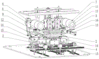
FIG. 1 is a perspective view of a bulk release film tearing mechanism;
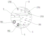
FIG. 2 is an enlarged view of portion A of FIG. 1;
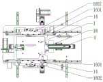
FIG. 3 is a front view of a release film batch film tearing mechanism;
FIG. 4 is a top plan view of the positional relationship of the table, steel plate gripping mechanism and carrier transport mechanism;
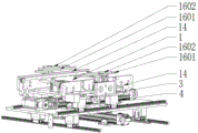
FIG. 5 is a perspective view of the positional relationship of the table, the steel plate gripping mechanism and the carrier transport mechanism;
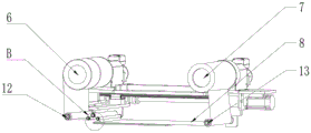
FIG. 6 is a schematic view showing a state in which the adhesive tape is wound between the rolls and on the positioning steel tape in a state in which the adhesive tape is peeled;
fig. 7 is an enlarged view of a portion B in fig. 6.
Detailed Description
So that the objects, advantages and features of the present invention can be more clearly and specifically set forth, a more particular description of the preferred embodiments will be rendered by the following non-limiting description thereof. The embodiment is only a typical example of the technical scheme of the invention, and all technical schemes formed by adopting equivalent substitution or equivalent transformation fall within the scope of the invention.
It is also stated that, in the description of the aspects, it should be noted that the directions or positional relationships indicated by the terms "center", "upper", "lower", "left", "right", "front", "rear", "inner", "outer", etc. are based on the directions or positional relationships shown in the drawings, are merely for convenience of description and simplification of description, and do not indicate or imply that the devices or elements referred to must have a specific orientation, be configured and operated in a specific orientation, and thus should not be construed as limiting the present invention.
Furthermore, the terms "first," "second," and the like in this description are used for descriptive purposes only and are not to be construed as indicating or implying a ranking of importance, or as implicitly indicating the number of technical features shown. Thus, a feature defining "a first" or "a second" may explicitly or implicitly include one or more such feature. In the present invention, the meaning of "plurality" means two or more, unless specifically defined otherwise.
The invention discloses a release film batch film tearing mechanism, which is shown in figures 1-3 and comprises:
the device comprises a workbench 1, wherein a carrier 2 for placing a workpiece is arranged on the workbench 1, a linear module is arranged at the bottom of the workbench 1 and comprises a first sliding rail 4, the conveying direction of the first sliding rail 4 is the X-axis direction, the linear module further comprises a sliding table 3, the sliding table 3 reciprocates and translates along the first sliding rail 4 in the X-axis direction, the workbench 1 is arranged on the sliding table 3, in one embodiment, in order to improve the moving stability of the sliding table 3, guide rails are arranged at two sides of the first sliding rail 4 in parallel, sliding blocks are arranged at two sides of the bottom of the sliding table 3 and translate along the guide rails; the lifting cylinder is further arranged between the workbench 1 and the sliding table 3, and the workbench 1 is driven to lift through the cylinder and drives the carrier 2 placed at the top of the workbench 1 to lift together.
The positioning steel plate 5 is arranged at the top of the workbench 1 in a lifting manner and covers the carrier 2, specifically, when the carrier 2 is positioned on the workbench 1 and the release film is to be torn off, the positioning steel plate 5 is covered on the carrier 2, after the release film is torn off, before the carrier 2 needs to be rotated, the positioning steel plate 5 is taken away from the carrier, as shown in fig. 2, an avoidance hole 501 is formed in the position, corresponding to the release film of the workpiece, on the positioning steel plate 5, so that the release film is exposed out of the avoidance hole 501, specifically, when the workpiece is placed on the carrier 2, the release film is positioned at the top of the workpiece, when the positioning steel plate 5 is covered on the carrier 2, the workpiece passes through the avoidance hole 501 and exposes the release film at the top of the workpiece outside the avoidance hole 501, so that the release film is convenient to be torn off later, and the adhesive tape 8 is convenient to peel off from the surface of the positioning steel plate 5 is avoided;
the adhesive tape conveying mechanism comprises an adhesive tape unreeling roller 6 and an adhesive tape reeling roller 7 which are rotatably arranged at two sides of the workbench 1, wherein the adhesive tape unreeling roller 6 and the adhesive tape reeling roller 7 are connected through winding of adhesive tape 8, specifically, adhesive tape is arranged on the adhesive tape unreeling roller 6, the adhesive tape reeling roller 7 is used for collecting adhesive tape 8 waste materials after a release film is torn off, before the adhesive tape is used for the first time, the adhesive tape 8 of the adhesive tape unreeling roller 6 is pulled out and partially wound on the adhesive tape reeling roller 7, the adhesive tape 8 between the adhesive tape unreeling roller 6 and the adhesive tape reeling roller 7 passes over the position steel plate 5, the length of the adhesive tape 8 between the adhesive tape unreeling roller 6 and the adhesive tape reeling roller 7 is larger than the length of the position steel plate 5, and the width of the adhesive tape 8 is larger than or equal to the position steel plate 5, the adhesive tape 8 between the adhesive tape unreeling roller 6 and the adhesive tape reeling roller 7 is ensured to cover the whole position steel plate 5, before the release film 8 is torn off, the peeling mechanism 9 is arranged on one side of the position steel plate 5, the adhesive tape 9 is transferred to the position steel plate 5 along with the position steel plate 5, the tape 9 is gradually moved to the position steel plate 5 from the position steel plate 5, the position is stretched to the position steel plate 9, the peeling mechanism is gradually moves to the position steel plate 9, and the tape 9 is gradually moves to the position steel plate 9 from the position film 9 side to the position steel plate 5, and the position is gradually after the peeling mechanism is stretched to the position on the surface, and the surface is positioned.
The stripping mechanism 9 is movably arranged between the adhesive tape winding roller 7 and the adhesive tape unwinding roller 6, when the adhesive tape is torn off, the bottom of the stripping mechanism 9 is higher than the upper surface of the positioning steel plate 5, and the adhesive tape 8 on the surface of the positioning steel plate 5 is torn off when the stripping mechanism 9 passes over the positioning steel plate 5, wherein the stripping mechanism 9 comprises a stripping roller 901 and two tensioning rollers 902 which are arranged in a three-point positioning way, the stripping roller 901 is arranged between the two tensioning rollers 902, the height of the stripping roller is higher than that of the two tensioning rollers 902, the stripping roller 901 and the two tensioning rollers 902 are arranged in parallel with the adhesive tape winding roller 7 and the adhesive tape unwinding roller 6, the adhesive tape winding roller 7 and the adhesive tape unwinding roller 6 are higher than the stripping mechanism 9, the adhesive tape 8 between the adhesive tape unwinding roller 6 and the adhesive tape winding roller 7 is wound on the outer peripheral surface of the stripping roller, the two tensioning rollers 902 are respectively arranged below the two sides of the stripping roller 901, and the adhesive tape winding roller 901 can be used for ensuring the smooth rotation of the stripping roller 901 in the adhesive tape coating process.
In some embodiments, a second sliding rail 10 is arranged at the top of the first sliding rail 4 in parallel, the peeling mechanism 9 is connected with the second sliding rail 10 through a sliding block, and the peeling mechanism 9 is pushed by a motor screw to reciprocate on the second sliding rail 10 along the X-axis direction.
The two tensioning rollers 902 in the peeling mechanism 9 are equal in height and are equidistantly arranged between the two tensioning rollers 902 and the peeling roller 901, the adhesive tape 8 between the adhesive tape unreeling roller 6 and the adhesive tape reeling roller 7 is wound around the peeling roller 901 and the two tensioning rollers 902, specifically, the adhesive tape 8 passes through a gap between the tensioning rollers 902 and the peeling roller 901, one surface of the adhesive tape 8, which is not provided with an adhesive surface, bypasses the bottoms of the two tensioning rollers 902, one surface of the adhesive tape 8, which is provided with an adhesive surface, is wound on the peeling roller 901, and the outer circumferential surface of the peeling roller 901 is coated with an anti-adhesive coating, wherein the anti-adhesive coating on the upper surface of the positioning steel plate 5 and the outer circumferential surface of the peeling roller 901 can be an anti-adhesive ceramic coating or a silicon coating, which is the prior art, and is not repeated herein, and in some embodiments, the upper surface of the positioning steel plate 5 and the outer circumferential surface of the peeling roller 901 can be further provided with frosted surfaces.
As shown in fig. 7, when the adhesive tape is peeled off, a sticking boundary line d is formed at the junction between the adhesive tape 8 and the surface of the positioning steel plate 5, and as the peeling mechanism 9 is translated above the positioning steel plate, the sticking boundary line d gradually translates from one side of the positioning steel plate 5 to the other side of the positioning steel plate 5 at a constant speed along with the movement of the peeling mechanism, and when the adhesive tape on the upper surface of the positioning steel plate 5 is completely peeled off, the sticking boundary line d disappears.
The tension rollers 902 on two sides of the peeling roller 901 are arranged to adjust tightness between the peeling roller 901 and the adhesive tape 8 on the surface of the positioning steel plate 5 and peeling angle of the adhesive tape 8, when the peeling mechanism 9 passes over the positioning steel plate 5, the bottom of the tension roller 902 is higher than the upper surface of the positioning steel plate 5 by 5mm, when the peeling mechanism 9 peels off the adhesive tape 8 on the surface of the positioning steel plate 5, an included angle formed by the adhesive tape between the tension roller 902 and the positioning steel plate 5 on the side close to the adhesive boundary line d and the surface of the positioning steel plate 5 is called a peeling angle alpha, the peeling angle alpha is always 60 degrees, when the peeling angle of the adhesive tape 8 is overlarge, the contact surface between the tension roller 902 and the adhesive tape 8 is smaller, the tension control on the adhesive tape 8 is small, the peeling stability of the adhesive tape 8 is poor, the peeling force is difficult to control, the peeling effect of the release film is poor or the release film adhered on the adhesive tape 8 is caused to peel off in the peeling process of the adhesive tape 8; when the angle of the tearing film is too small, the stretching force of the stripping mechanism 9 on the adhesive tape 8 is large, the adhesive tape 8 is easy to deform or break, meanwhile, the moving resistance of the glass mechanism is increased due to too large pulling force, the stripping efficiency is reduced, when the angle alpha of the tearing film is 60 degrees, the tearing film effect can be ensured, the deformation caused by excessive stretching of the adhesive tape 8 can be avoided, and the stripping efficiency is also high.
The included angle beta formed by the connecting line a at the bottom of the two tensioning rollers 902 and the adhesive tape between the stripping roller 901 and the tensioning roller 902 should be greater than or equal to the film tearing angle, so that the tensioning roller 902 can contact and press the adhesive tape between the stripping roller 901 and the positioning steel plate 5, the control of the tension force of the adhesive tape between the stripping roller 901 and the positioning steel plate 5 is realized, the uniform speed movement of the pasting boundary line d is ensured, and the adhesive tape on the surface of the positioning steel plate 5 is stably stripped, therefore, the included angle beta is greater than or equal to 60 degrees, and preferably, the included angle beta is 65-75 degrees.
As shown in fig. 6, a first positioning roller 12 is arranged at the bottom of the tape unreeling roller 6, a second positioning roller 13 is arranged at the bottom of the tape reeling roller 7, the first positioning roller 12 and the second positioning roller 13 are at equal heights, specifically, when the peeling mechanism 9 starts to tear off the tape 8 on the surface of the positioning steel plate 5, the first positioning roller 12 and the second positioning roller 13 rotate clockwise, so that the height of the adhesive tape on the top of the positioning steel plate 5 is controlled, simultaneously, when the adhesive tape on the top of the positioning steel plate 5 is torn off, the tape unreeling roller 6 and the tape reeling roller 7 stop rotating, and the first positioning roller 12 and the second positioning roller 13 control the tensioning force of the adhesive tape 8 between the tape unreeling roller 6 and the tape reeling roller 7 in real time by controlling the rotating direction, and specifically, when the peeling mechanism 9 starts to tear off the adhesive tape 8 on the surface of the positioning steel plate 5, the first positioning roller 12 rotates clockwise, the second positioning roller 13 rotates anticlockwise, gradually tightens the adhesive tape on the reeling roller 6 and the tape reeling roller 7, and prevents the adhesive tape 8 from being adhered on the surface of a workpiece 8 after the adhesive tape is removed, and the adhesive tape is prevented from being adhered to the surface of the workpiece 8; when the tape unreeling roller 6 unreels and the tape reeling roller 7 winds after the stripping is finished, the rotating direction of the first positioning roller 12 is the same as the rotating direction of the tape unreeling roller 6, and the rotating direction of the second positioning roller 13 is the same as the rotating direction of the tape reeling roller 7, so that the tape unreeling and reeling are assisted; in some embodiments, the tape unreeling roller 6, the tape reeling roller 7, the first positioning roller 12 and the second positioning roller 13 are electric rollers with adjustable rotation directions, and in other embodiments, the four rollers are respectively controlled to rotate by different motors.
Since the rotation of the tape winding roller 7 and the tape unwinding roller 6 is stopped during the process of peeling the tape 8, the tension of the tape 8 between the tape unwinding roller 6 and the tape winding roller 7 is controlled by the first positioning roller 12 and the second positioning roller 13, so that the moving direction of the peeling mechanism 9 (i.e., the peeling direction of the tape 8) is not limited by the winding and unwinding directions of the tape, specifically, the moving direction of the peeling mechanism 9 may be set to the side of the tape winding roller 7 where the tape unwinding roller 6 is located to finish peeling the tape 8, or set to be set to the side of the tape unwinding roller 6 where the tape winding roller 7 is located to finish peeling the tape 8, after the peeling mechanism 9 finishes a peeling process once, no reset is required, and the peeling direction of the peeling mechanism 9 is opposite to the peeling direction of the previous operation in the next operation, thereby improving the working efficiency.
As shown in fig. 4 and 5, two ends of the workbench 1 are further provided with carrier conveying mechanisms 14 for conveying the carriers 2 along the X-axis direction, the carrier conveying mechanisms 14 are arranged on the sliding table 3, the bottom of one carrier conveying mechanism 14 is provided with a conveying guide rail 15 along the Y-axis direction, the carrier conveying mechanisms 14 are close to or far away from the other carrier conveying mechanism 14 along the conveying guide rail 15, so as to regulate and control the distance between the two carrier conveying mechanisms 14, one side of each carrier conveying mechanism 14 is provided with a gear cylinder 18 in a lifting manner, the gear cylinders 18 are used for positioning the carriers 2, each carrier conveying mechanism 14 comprises a conveying belt and driven gears arranged on two sides of the conveying belt, a driving gear and a tensioning gear are arranged between the two driven gears, the conveying belt is wound between the driving gear, the driven gears and the tensioning gears, the driving gears are connected with a motor, the two carrier conveying mechanisms 14 are arranged in parallel, the conveying heights of the conveying belts on the two carrier conveying mechanisms 14 are identical, the two sides of the bottom of each carrier conveying mechanism 2 are placed on the conveying belt, and the conveying belt is arranged on the workbench 1 in the lifting direction, and can move to the workbench 1 along the height direction when the conveying belt is required to be lifted to the workbench 1; when the carrier 2 needs to be lifted, the carrier 2 is moved to the position right above the workbench 1 by the carrier conveying mechanism 14, and then the carrier 2 is lifted or lowered by the workbench 1.
In some embodiments, the carrier conveying mechanism 14 is further provided with a sensor for sensing the position of the carrier 2, where the sensor may be one or more of a photoelectric sensor and a contact sensor, and when the sensor senses that the carrier 2 is located at the top of the workbench 1, in-place information is conveyed to a system, and the system controls the gear cylinder 18 to rise, so as to prevent the carrier 2 from moving continuously, where the setting and working process of the photoelectric sensor and the contact sensor are in the prior art and are not described herein.
In some embodiments, two sides of the carrier conveying mechanism 14 are respectively connected with a conveying line, so that the carrier 2 with the workpiece to be processed is conveyed onto the carrier conveying mechanism 14 (i.e. feeding) or the carrier 2 with the workpiece to be processed is output (i.e. discharging), the feeding position and the discharging position of the carrier 2 can be adjusted in real time according to the position of the peeling mechanism 9, specifically, the feeding position of the carrier 2 is located on the side of the carrier conveying mechanism 14 close to the peeling mechanism, and the discharging position of the carrier 2 is located on the side of the carrier conveying mechanism 14 far away from the peeling mechanism.
The pressing mechanism comprises a pressing plate 11 driven to rise and fall by an air cylinder, a pressing head 17 is arranged at the bottom of the pressing plate 11, the pressing head 17 corresponds to the avoidance holes 501 on the positioning steel plate 5 one by one up and down, after the adhesive tape 8 is pasted on the surface of the positioning steel plate 5, the adhesive surface of the adhesive tape 8 and the release film stretching out of the avoidance holes 501 are pressed by the pressing head 17, the adhesive film and the adhesive tape 8 are firmly pasted, meanwhile, the pressing head 17 is only pressed by the release film and the adhesive tape 8, the surface of the positioning steel plate cannot be contacted, the adhesive force between the adhesive tape 8 and the surface of the positioning steel plate 5 is prevented from being increased, and the adhesive tape 8 is convenient to strip subsequently.
The pressure head 17 comprises a spring thimble 1701, a resin pressing block 1702 and a buffer rubber cushion 1703 which are sequentially arranged from top to bottom, the effective compression stroke of the spring thimble 1701 is 5mm, the thickness of the resin pressing block 1702 is 5mm, the thickness of the buffer rubber cushion 1703 is 1.6 mm, the Shore hardness is 60 ℃, the pressure head 17 reduces the pressing force on a workpiece through the spring thimble 1701 and the buffer rubber cushion 1703, the workpiece or the adhesive tape 8 is prevented from being damaged, and meanwhile the bonding degree between the adhesive surface of the adhesive tape 8 and a release film at the top of the workpiece is ensured.
In some embodiments, the carrier 2 is provided with a plurality of hollow holes (not shown in the figure), the workpiece is placed on the top of the hollow holes, the workbench 1 is provided with a vacuum air channel (not shown in the figure) for positioning the workpiece, when the carrier 2 is placed on the workbench 1, the vacuum air channel is opened, the carrier 2 is communicated with the vacuum air channel through the hollow holes and adsorbs the bottom of the workpiece, so that the workpiece is positioned, and the workpiece is prevented from being shifted or taken away when the pressure head 17 presses the top of the workpiece or when the adhesive tape 8 peels off the release film; in other embodiments, the avoiding hole 501 on the positioning steel plate 5 is disposed right above the hollowed hole, so that the positioning steel plate 5 and the carrier 2 are positioned, the workpiece is positioned in the hollowed hole, and when the positioning steel plate 5 covers the carrier 2, a part of the top of the workpiece attached with a release film passes through the avoiding hole 501 disposed on the positioning steel plate and is exposed outside the avoiding hole.
The total thickness of the adhesive tape 8 is 50 um+/-2 um, the adhesive tape comprises a PET film layer and an acrylic adhesive layer, the surface of the acrylic adhesive layer is an adhesive surface, the thickness of the PET film layer is 25um, the thickness of the acrylic adhesive layer is 25 um+/-2 um, the toughness of the adhesive tape 8 and the viscosity of the adhesive surface can be ensured, and the adhesive tape 8 is subjected to viscosity test by a 180-degree peel force testing machine, wherein the temperature of the test is: 23 ℃, the humidity is: under 56% of the test environment, 180 ° peel force was measured as: 8N/25MM, and in addition, the initial adhesion test of the pressure-sensitive adhesive tape was carried out on the above-mentioned adhesive tape 8 by using an initial adhesion tester (national standard GB-T4852-2002), and the initial adhesion of the above-mentioned adhesive tape 8 was tested as follows: the steel ball No. 16, therefore, the stripping force and the initial adhesion performance of the adhesive tape 8 are better, and the stripping of the release film can be better realized.
The two ends of the positioning steel plate 5 are provided with steel plate clamping mechanisms 16, the steel plate clamping mechanisms 16 comprise an electromagnetic iron plate 1601 for sucking the positioning steel plate 5 and a mounting plate 1602 for positioning the electromagnetic iron plate 1601, the mounting plate 1602 is driven to lift by an air cylinder, the two steel plate clamping mechanisms 16 are driven to synchronously move towards each other or back to each other by the air cylinder, when the positioning steel plate 5 needs to be taken away from the top of the carrier 2, the steel plate clamping mechanisms 16 are driven to synchronously move towards each other by the air cylinder to be above the positioning steel plate 5, the electromagnetic iron plate 1601 is electrified, and after the electromagnetic iron plate 1601 sucks the positioning steel plate 5, the clamping mechanisms drive the positioning steel plate 5 to lift and separate from the carrier 2; when the carrier 2 with the processed workpiece is placed right above the workbench 1, the steel plate clamping mechanism 16 drives the positioning steel plate 5 to descend until the positioning steel plate 5 is placed on the carrier 2, the electromagnetic iron plate 1601 is powered off, and the steel plate clamping mechanism 16 is driven by the air cylinder to move back to the two ends of the positioning steel plate 5 and then is driven by the air cylinder to descend, so that interference is avoided.
The invention also discloses a release film batch film tearing method, which uses the release film batch film tearing mechanism, and comprises the following steps:
s1: the adhesive tape 8 on the surface of the adhesive tape unreeling roller 6 is pulled out and is partially wound on the adhesive tape reeling roller 7, so that a section of adhesive tape 8 is reserved between the adhesive tape unreeling roller 6 and the adhesive tape reeling roller 7, and the adhesive tape 8 is arranged right above the workbench 1;
s2: placing the carrier 2 with the workpiece to be processed on a carrier conveying mechanism 14, and positioning the carrier 2 through a gear cylinder 18 after the carrier conveying mechanism 14 conveys the carrier 2 to the position right above the workbench 1;
s3: the workbench 1 ascends and supports the carrier 2 to leave the carrier conveying mechanism 14, the steel plate clamping mechanism 16 places the positioning steel plate 5 on the top of the carrier 2 and leaves the carrier, and the workbench 1 drives the carrier 2 and the positioning steel plate 5 to move upwards until the adhesive tape 8 is attached to the upper surface of the positioning steel plate 5;
s4: after each pressure head 17 at the bottom of the pressure plate 11 is aligned with each release film extending out of the avoiding hole 501, the pressure plate 11 drives the pressure heads 17 to descend until the adhesive surface of the adhesive tape 8 is attached to the release film, and the pressure plate 11 drives the pressure heads 17 to ascend and reset;
s5: the adhesive tape unreeling roller 6 and the adhesive tape winding roller 7 stop rotating, a stripping mechanism 9 connected with the adhesive tape 8 gradually moves to the upper part of the positioning steel plate 5 from one side of the positioning steel plate 5, and gradually lifts the adhesive tape 8 on the surface of the positioning steel plate 5;
s6: and the stripping mechanism stops moving after leaving the upper part of the positioning steel plate, the adhesive tape unreeling roller and the adhesive tape reeling roller synchronously unreel and receive materials, the first positioning roller and the adhesive tape unreeling roller rotate in the same direction, the second positioning roller and the adhesive tape reeling roller rotate in the same direction, and the adhesive tape adhered with the release film is reeled onto the adhesive tape reeling roller to finish film tearing.
The invention has various embodiments, and all technical schemes formed by equivalent transformation or equivalent transformation fall within the protection scope of the invention.
Claims (10)
1. From membrane batch dyestripping mechanism, its characterized in that: comprising the following steps:
the device comprises a workbench, wherein a carrier for placing a workpiece is arranged on the workbench, a linear module is arranged at the bottom of the workbench, the linear module comprises a first sliding rail arranged along the X-axis direction and a sliding table translated along the first sliding rail, and the workbench is driven by an air cylinder to be arranged on the sliding table in a lifting manner;
the positioning steel plate is arranged at the top of the workbench in a lifting manner and covers the carrier, an avoidance hole is formed in the positioning steel plate corresponding to the position of the release film of the workpiece, the release film is exposed out of the avoidance hole, and an anti-adhesive coating is arranged on the upper surface of the positioning steel plate;
the adhesive tape conveying mechanism comprises adhesive tape unreeling rollers and adhesive tape reeling rollers which are arranged on two sides of the workbench, wherein the adhesive tape unreeling rollers and the adhesive tape reeling rollers are connected through adhesive tape winding, and adhesive tape between the adhesive tape unreeling rollers and the adhesive tape reeling rollers passes through the position right above the positioning steel plate;
the stripping mechanism is movably arranged between the adhesive tape winding roller and the adhesive tape unwinding roller, when the adhesive tape is stripped, the bottom of the stripping mechanism is higher than the upper surface of the positioning steel plate, the adhesive tape on the surface of the positioning steel plate is stripped while passing over the positioning steel plate, the stripping mechanism comprises a stripping roller and two tensioning rollers which are positioned at three points, the stripping roller is arranged between the two tensioning rollers, the height of the stripping roller is higher than that of the two tensioning rollers, the adhesive tape between the adhesive tape unwinding roller and the adhesive tape winding roller is wound on the outer peripheral surface of the stripping roller, the two tensioning rollers compress the adhesive tape on two sides of the stripping roller, and the outer peripheral surface of the stripping roller is coated with an anti-adhesive coating;
the pressing mechanism comprises a pressing plate driven to rise and fall by an air cylinder, a pressing head is arranged at the bottom of the pressing plate, and the pressing head corresponds to the avoidance holes in the positioning steel plate one by one.
2. The release film batch film tearing mechanism of claim 1, wherein: the carrier is provided with a plurality of hollow holes, and the workbench is provided with a vacuum gas circuit for positioning a workpiece.
3. The release film batch film tearing mechanism of claim 1, wherein: the two tensioning rollers in the stripping mechanism are equal in height and are arranged at equal intervals between the two tensioning rollers and the stripping roller.
4. A release film batch film tearing mechanism according to claim 3, wherein: the bottom of the adhesive tape unreeling roller is provided with a first positioning roller, the bottom of the adhesive tape winding roller is provided with a second positioning roller, the adhesive tape between the adhesive tape unreeling roller and the adhesive tape winding roller is pressed downwards by the first positioning roller and the second positioning roller, and the heights of the first positioning roller and the second positioning roller are equal.
5. A release film batch film tearing mechanism according to claim 3, wherein: when the stripping mechanism passes over the positioning steel plate, the bottom of the tensioning roller is higher than the upper surface of the positioning steel plate by 5mm, a pasting boundary line d is formed at the joint of the adhesive tape and the surface of the positioning steel plate when the adhesive tape is stripped, a film tearing angle alpha is formed between the adhesive tape between the tensioning roller and the positioning steel plate, which are close to one side of the pasting boundary line d, and the surface of the positioning steel plate, the film tearing angle alpha is equal to 60 degrees, and an included angle beta formed between a connecting line a at the bottom of two tensioning rollers and the adhesive tape between the stripping roller and the tensioning roller is equal to or more than 60 degrees.
6. The release film batch film tearing mechanism of claim 5, wherein: the workbench is characterized in that carrier conveying mechanisms for conveying carriers are further arranged at two ends of the workbench, the carrier conveying mechanisms are arranged on the sliding table, a conveying guide rail is arranged at the bottom of one carrier conveying mechanism along the Y-axis direction, the carrier conveying mechanisms are close to or far away from the other carrier conveying mechanism along the conveying guide rail, and a gear cylinder is arranged on one side of the carrier conveying mechanism in a liftable mode.
7. The release film batch film tearing mechanism of claim 1, wherein: the pressure head comprises a spring thimble, a resin pressing block and a buffer rubber cushion which are sequentially arranged from top to bottom, the effective compression stroke of the spring thimble is 5mm, the thickness of the resin pressing block is 5mm, and the thickness of the buffer rubber cushion is 1.6 mm, and the Shore hardness is 60 degrees.
8. The release film batch film tearing mechanism of claim 1, wherein: the total thickness of the adhesive tape is 50 um+/-2 um, the adhesive tape comprises a PET film layer and an acrylic adhesive layer, the thickness of the PET film layer is 25um, and the thickness of the acrylic adhesive layer is 25 um+/-2 um.
9. The release film batch film tearing mechanism of claim 1, wherein: the two ends of the positioning steel plate are provided with steel plate clamping mechanisms, the positioning steel plate clamping mechanisms comprise an electromagnetic iron plate for sucking the positioning steel plate and a mounting plate for positioning the electromagnetic iron plate, the mounting plate is driven to lift by an air cylinder, and the two steel plate clamping mechanisms are driven to synchronously move in opposite directions or in opposite directions by the air cylinder.
10. The batch film tearing method for the release films is characterized by comprising the following steps of: use of a release film batch film tearing mechanism according to any of claims 1-9, comprising the steps of:
s1: pulling out the adhesive tape on the surface of the adhesive tape unreeling roller and partially winding the adhesive tape on the adhesive tape reeling roller, so that a section of adhesive tape is reserved between the adhesive tape unreeling roller and the adhesive tape reeling roller, and the adhesive tape is arranged right above the workbench;
s2: placing a carrier provided with a workpiece to be processed on a carrier conveying mechanism, and positioning the carrier through a gear cylinder after the carrier conveying mechanism conveys the carrier to the position right above a workbench;
s3: the workbench ascends and supports the carrier to leave the carrier conveying mechanism, the steel plate clamping mechanism places the positioning steel plate at the top of the carrier and leaves the carrier, and the workbench drives the carrier and the positioning steel plate to move upwards until the adhesive tape is attached to the upper surface of the positioning steel plate;
s4: after each pressure head at the bottom of the pressure plate is aligned with each release film extending out of the avoidance hole, the pressure plate drives the pressure heads to descend until the adhesive surface of the adhesive tape is attached to the release film, and then the pressure plate drives the pressure heads to ascend and reset;
s5: the adhesive tape unreeling roller and the adhesive tape winding roller stop rotating, a stripping mechanism connected with the adhesive tape gradually moves to the upper part of the positioning steel plate from one side of the positioning steel plate, and gradually lifts the adhesive tape on the surface of the positioning steel plate;
s6: and the stripping mechanism stops moving after leaving the upper part of the positioning steel plate, the adhesive tape unreeling roller and the adhesive tape reeling roller synchronously unreel and receive materials, the first positioning roller and the adhesive tape unreeling roller rotate in the same direction, the second positioning roller and the adhesive tape reeling roller rotate in the same direction, and the adhesive tape adhered with the release film is reeled onto the adhesive tape reeling roller to finish film tearing.
Priority Applications (1)
| Application Number | Priority Date | Filing Date | Title |
|---|---|---|---|
| CN202310358842.3A CN116061541B (en) | 2023-04-06 | 2023-04-06 | Batch film tearing mechanism and method for release films |
Applications Claiming Priority (1)
| Application Number | Priority Date | Filing Date | Title |
|---|---|---|---|
| CN202310358842.3A CN116061541B (en) | 2023-04-06 | 2023-04-06 | Batch film tearing mechanism and method for release films |
Publications (2)
| Publication Number | Publication Date |
|---|---|
| CN116061541A CN116061541A (en) | 2023-05-05 |
| CN116061541B true CN116061541B (en) | 2023-06-27 |
Family
ID=86183965
Family Applications (1)
| Application Number | Title | Priority Date | Filing Date |
|---|---|---|---|
| CN202310358842.3A Active CN116061541B (en) | 2023-04-06 | 2023-04-06 | Batch film tearing mechanism and method for release films |
Country Status (1)
| Country | Link |
|---|---|
| CN (1) | CN116061541B (en) |
Families Citing this family (1)
| Publication number | Priority date | Publication date | Assignee | Title |
|---|---|---|---|---|
| CN117246620B (en) * | 2023-11-08 | 2024-02-27 | 厦门普诚科技有限公司 | Double-sided tape dyestripping machine |
Family Cites Families (8)
| Publication number | Priority date | Publication date | Assignee | Title |
|---|---|---|---|---|
| CN201257792Y (en) * | 2008-04-09 | 2009-06-17 | 阳程科技股份有限公司 | Attachment apparatus |
| TW201704034A (en) * | 2015-07-24 | 2017-02-01 | Evest Corp | Release film peeling device and method thereof capable of conveniently and fast peeling the release film from the substrate and saving labor hour and cost |
| CN110589598A (en) * | 2019-08-21 | 2019-12-20 | 深圳市集银科技有限公司 | Automatic adhesive tape stripping device |
| CN212891136U (en) * | 2020-06-23 | 2021-04-06 | 深圳橙子自动化有限公司 | Film stripping device and film sticking machine |
| CN111806820A (en) * | 2020-08-12 | 2020-10-23 | 深圳市新嘉智诚自动化有限公司 | Film tearing method, film tearing mechanism applying same and film tearing equipment |
| CN214165538U (en) * | 2020-10-16 | 2021-09-10 | 昆山峰实电子外观应用科技有限公司 | Automatic tear 3D physique film protection film mechanism off |
| CN214606449U (en) * | 2020-12-06 | 2021-11-05 | 无锡沃格自动化科技股份有限公司 | Automatic dyestripping mechanism of optical diaphragm |
| CN214983998U (en) * | 2021-05-28 | 2021-12-03 | 苏州安洁科技股份有限公司 | Film tearing mechanism for thin film material |
-
2023
- 2023-04-06 CN CN202310358842.3A patent/CN116061541B/en active Active
Also Published As
| Publication number | Publication date |
|---|---|
| CN116061541A (en) | 2023-05-05 |
Similar Documents
| Publication | Publication Date | Title |
|---|---|---|
| JP4255433B2 (en) | Single wafer laminating method and apparatus using the same | |
| CN116061541B (en) | Batch film tearing mechanism and method for release films | |
| JPH07123109B2 (en) | Dry film resist transfer / lamination system for semiconductor wafers | |
| CN108963341B (en) | Method for sticking gummed paper on lithium battery | |
| CN114132792A (en) | Novel curved surface cladding equipment | |
| JP3637350B2 (en) | Adhesive tape strip sticking device | |
| CN213139370U (en) | Automatic labeling machine | |
| CN110911333B (en) | Tape applying apparatus | |
| CN212099690U (en) | Label peeling equipment | |
| JPH08133560A (en) | Applying device and applying method of adhesive tape piece | |
| CN113964366A (en) | Automatic tail glue corner pressing machine for battery | |
| KR20030060471A (en) | Method and apparatus for removing tape cover for manufacturing semiconductor package | |
| JP2024503955A (en) | film packaging equipment | |
| CN210940453U (en) | Automatic paster device | |
| CN113772475A (en) | Blue glue pasting device for mobile phone toughened film packaging | |
| CN115071122B (en) | Automatic waterproof film pasting device and automatic waterproof film stripping method | |
| CN112571917A (en) | Glass feeding method and device for backlight assembly | |
| CN112193834A (en) | Feeding module of rubberizing complete machine | |
| CN216611954U (en) | Adhesive tape sticking machine | |
| CN218366490U (en) | Micro-film material laminating equipment | |
| KR20080088374A (en) | Apparatus for and method manufacturing photosensitive laminated body | |
| CN219989615U (en) | Semi-automatic 3D curved surface screen pad pasting equipment | |
| CN215710329U (en) | Reel-to-reel UV transfer machine | |
| CN219651579U (en) | Automatic labeling machine for fast-paced vehicle shells | |
| CN112310337B (en) | Rubberizing process, rubberizing device and double-sided rubberizing device |
Legal Events
| Date | Code | Title | Description |
|---|---|---|---|
| PB01 | Publication | ||
| PB01 | Publication | ||
| SE01 | Entry into force of request for substantive examination | ||
| SE01 | Entry into force of request for substantive examination | ||
| GR01 | Patent grant | ||
| GR01 | Patent grant |