CN115824312A - Detection equipment for vehicle-mounted screen circuit board - Google Patents
Detection equipment for vehicle-mounted screen circuit board Download PDFInfo
- Publication number
- CN115824312A CN115824312A CN202310043094.XA CN202310043094A CN115824312A CN 115824312 A CN115824312 A CN 115824312A CN 202310043094 A CN202310043094 A CN 202310043094A CN 115824312 A CN115824312 A CN 115824312A
- Authority
- CN
- China
- Prior art keywords
- plate
- circuit board
- fixedly connected
- detection
- positioning
- Prior art date
- Legal status (The legal status is an assumption and is not a legal conclusion. Google has not performed a legal analysis and makes no representation as to the accuracy of the status listed.)
- Pending
Links
- 238000001514 detection method Methods 0.000 title claims abstract description 111
- 230000007246 mechanism Effects 0.000 claims abstract description 177
- 230000000007 visual effect Effects 0.000 claims abstract description 24
- 238000007689 inspection Methods 0.000 claims description 10
- 239000000523 sample Substances 0.000 claims description 9
- 230000005540 biological transmission Effects 0.000 claims description 7
- 238000012360 testing method Methods 0.000 claims description 7
- 238000012546 transfer Methods 0.000 abstract description 17
- 238000012797 qualification Methods 0.000 abstract description 13
- 238000000034 method Methods 0.000 description 8
- 238000005192 partition Methods 0.000 description 6
- 238000011179 visual inspection Methods 0.000 description 3
- 206010063385 Intellectualisation Diseases 0.000 description 1
- 230000004075 alteration Effects 0.000 description 1
- 230000009286 beneficial effect Effects 0.000 description 1
- 238000010586 diagram Methods 0.000 description 1
- 238000007599 discharging Methods 0.000 description 1
- 238000005516 engineering process Methods 0.000 description 1
- 238000012986 modification Methods 0.000 description 1
- 230000004048 modification Effects 0.000 description 1
- 238000006467 substitution reaction Methods 0.000 description 1
Images


Classifications
-
- Y—GENERAL TAGGING OF NEW TECHNOLOGICAL DEVELOPMENTS; GENERAL TAGGING OF CROSS-SECTIONAL TECHNOLOGIES SPANNING OVER SEVERAL SECTIONS OF THE IPC; TECHNICAL SUBJECTS COVERED BY FORMER USPC CROSS-REFERENCE ART COLLECTIONS [XRACs] AND DIGESTS
- Y02—TECHNOLOGIES OR APPLICATIONS FOR MITIGATION OR ADAPTATION AGAINST CLIMATE CHANGE
- Y02W—CLIMATE CHANGE MITIGATION TECHNOLOGIES RELATED TO WASTEWATER TREATMENT OR WASTE MANAGEMENT
- Y02W30/00—Technologies for solid waste management
- Y02W30/50—Reuse, recycling or recovery technologies
- Y02W30/82—Recycling of waste of electrical or electronic equipment [WEEE]
Abstract
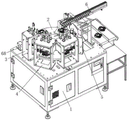
The invention discloses a detection device of a vehicle-mounted screen circuit board, which comprises a workbench, wherein a rotating mechanism for rotationally feeding the circuit board is fixedly arranged at the top of the workbench, and a pressing mechanism for pressing and positioning the circuit board is fixedly arranged at the top of the workbench and above the rotating mechanism. The invention can convey the circuit board to be detected to the corresponding pressing mechanism, two groups of jig detection mechanisms and visual detection mechanism to carry out omnibearing detection on the circuit board by arranging the rotating mechanism, the jig detection mechanism carries out circuit board detection by utilizing the detection mode of the pin jig, the camera in the visual detection mechanism is arranged as a CCD lens, and the detection mode of the mutual matching of the CCD lens and the pin jig forms a whole set of detection equipment, can detect the pressure, surface flaws and the like of the circuit board, and the arranged shifting mechanism can transfer the detected circuit board according to the qualification or the non-qualification.
Description
Technical Field
The invention relates to the technical field of circuit board detection, in particular to a detection device for a vehicle-mounted screen circuit board.
Background
At the present stage, along with the continuous popularization of intellectuality, car circuit board product wide use, market demand is sharply increased day by day, the product requirement is more and more accurate, electrical apparatus performance also needs to be tested through more intelligent means, and a lot of detection mode all is artifical to carry out manual detection to the circuit board one by one among the current testing process, and artifical detection time measuring can appear various problems, can not accomplish relative stable value, artifical easy undetected and detection efficiency low in long-time testing process, so can't guarantee the result of detection, can't guarantee detection efficiency, for this reason, we provide the check out test set of on-vehicle screen circuit board.
Disclosure of Invention
The invention aims to provide a detection device for a vehicle-mounted screen circuit board, which aims to solve the problems to be solved in the background technology.
In order to achieve the purpose, the invention provides the following technical scheme: the utility model provides a check out test set of on-vehicle screen circuit board, includes the workstation, the top fixed mounting of workstation has the rotary mechanism that carries out rotatory pay-off to the circuit board, the top of workstation and the top fixed mounting that is located rotary mechanism have the pressing mechanism who carries out the pressfitting location to the circuit board, the top of workstation and the top that is located rotary mechanism are provided with two tool detection mechanism that detect to the circuit board, the top of workstation is provided with the visual detection mechanism that carries out the flaw detection to the circuit board that rotary mechanism carried, the top of workstation is provided with the year mechanism that moves of unloading of taking to rotary mechanism top circuit board.
With the continuous popularization of intellectualization, the automobile circuit board products are widely used, the market demand is increased day by day, and the product requirements are more and more precise.
In addition, the whole device only needs manual loading and unloading in the using process, manual operation is replaced by the movement of the automatic mechanism in the detecting process, the position of a workpiece is ensured by the arrangement of the pressing mechanism, the detecting accuracy is realized by the two jig detecting mechanisms, the appearance detection is realized by the visual detecting mechanism, the qualified reliability of a detecting result is ensured, and the possibility of missing detection and low detecting efficiency caused by manual long-time working detection is avoided by the arrangement.
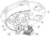
Preferably, the rotating mechanism comprises a first positioning plate, a divider, a first connecting plate and a first motor, the divider is fixedly mounted at the top of the workbench, the output shaft of the divider is fixedly mounted with the first positioning plate, one side of the inner wall of the workbench is fixedly mounted with the first connecting plate, one side of the first connecting plate is fixedly mounted with the first motor, the output end of the first motor is fixedly connected with a second belt pulley, the input shaft of the divider is fixedly connected with a first belt pulley, the first belt pulley is mutually connected with the outer surface of the second belt pulley through a connecting belt, six groups of positioning stations are fixedly mounted at the top of the first positioning plate, a second positioning plate is fixedly connected at the top of the first positioning plate, and a photoelectric sensor is fixedly mounted at the top of the second positioning plate and at a position corresponding to the positioning stations.
Preferably, the pressing mechanism comprises a first support frame and a first top plate, the first support frame is fixedly mounted at the top of the workbench, the top of the first support frame is fixedly provided with the first top plate, the top of the first top plate is provided with a first pen-shaped cylinder, the output end of the first pen-shaped cylinder and the position corresponding to the positioning station are fixedly connected with a first pressing plate through a first cylinder limiting block, four groups of first limiting seats are fixedly mounted on the surface of the first top plate, a first guide shaft is slidably connected inside the first limiting seats, the bottom of the first guide shaft penetrates through the top of the first top plate and is fixedly mounted at the top of the first pressing plate, the tops of the two groups of first guide shafts are fixedly connected through a second connecting plate, and the top of the first top plate is fixedly connected with a first guide shaft limiting block below the second connecting plate.
Preferably, the jig detection mechanism comprises a second support frame and a second top plate, the second support frame is fixedly installed at the top of the workbench, the top of the second support frame is fixedly connected with the second top plate, the top of the second top plate is fixedly provided with a second pen-shaped air cylinder, the output end of the second pen-shaped air cylinder and the position corresponding to the positioning station are fixedly connected with a second pressing plate through a second air cylinder limiting block, two sides of the bottom of the second pressing plate are fixedly connected with supporting plates, the surface of each supporting plate is fixedly provided with a needle card positioning plate through two needle card positioning plate fixing devices, the top of each needle card positioning plate is fixedly connected with a data transmission interface, the surface of each needle card positioning plate is provided with a plurality of groups of probes, the surface of the second top plate is fixedly provided with a plurality of groups of second limiting seats, the inside of each second limiting seat is slidably provided with a second guide shaft, and the bottom of each second guide shaft penetrates through the top of the second top plate and is fixedly installed at the top of the second pressing plate.
Preferably, the tops of the two sets of second guide shafts are fixedly connected through a third connecting plate, a hydraulic buffer is fixedly mounted on the surface of the third connecting plate, and one end of the hydraulic buffer is fixedly mounted on the top of the second top plate.
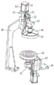
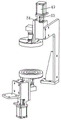
Preferably, visual detection mechanism includes third support frame and second location fixed block, third support frame fixed mounting is in the top of workstation, one side of third support frame and the top fixed mounting who is located the location station have actuating mechanism, the first camera of actuating mechanism's one end fixedly connected with, there is first light source one side of actuating mechanism and the below that is located first camera through first light source fixed plate fixed mounting, there is actuating mechanism in the surface of workstation and the below that is located the location station through second location fixed block fixed mounting, there is the second camera one side of actuating mechanism and the fixed mounting that corresponds first light source fixed plate, there is the second light source one side of actuating mechanism and the top that is located the second camera through second light source fixed plate fixed mounting.
Preferably, the driving mechanism comprises a first positioning fixing block and a second motor, the second motor is fixedly mounted at the top of the first positioning fixing block, the output end of the second motor is fixedly connected with a screw shaft, a first linear guide rail is fixedly mounted inside the first positioning fixing block, a movable positioning plate is slidably connected to the outer surface of the first linear guide rail, a threaded sleeve matched with the screw shaft is arranged on the outer surface of the screw shaft, and the threaded sleeve is fixedly mounted on one side of the movable positioning plate.
Preferably, move and carry mechanism and include fourth support frame, linear electric motor and cylinder fixed block, fourth support frame fixed mounting is in the top of workstation, one side fixed mounting of fourth support frame has linear electric motor, linear electric motor workstation fixedly connected with cylinder fixed block, cylinder fixed block fixed surface installs second linear guide, second linear guide's outer wall is provided with the clamping jaw locating plate, the bottom fixedly connected with finger cylinder of clamping jaw locating plate, the output fixedly connected with grip block of finger cylinder.
Preferably, one side of the workbench is provided with a blanking mechanism, the blanking mechanism comprises a blanking frame and a conveying belt, the top of the blanking frame is provided with the conveying belt, a partition plate is arranged above the conveying belt and divides the conveying belt into a first conveying position and a second conveying position, and two groups of blanking plates which are obliquely arranged are fixedly arranged on one side of the top of the blanking frame, which is located on the first conveying position and the second conveying position.
Compared with the prior art, the invention has the following beneficial effects:
the invention can convey the circuit board to be detected to the corresponding pressing mechanism, two groups of jig detection mechanisms and visual detection mechanism to carry out omnibearing detection on the circuit board by arranging the rotating mechanism, the jig detection mechanism carries out circuit board detection by utilizing the detection mode of the pin jig, the camera in the visual detection mechanism is arranged as a CCD lens, and the detection mode of the mutual matching of the CCD lens and the pin jig forms a whole set of detection equipment, can detect the pressure, surface flaws and the like of the circuit board, and the arranged shifting mechanism can transfer the detected circuit board according to the qualification or the non-qualification.
The invention is a semi-automatic detection process, only manual feeding and discharging are needed, the detection process is realized by the movement of the automatic mechanism instead of manual operation, the position of a workpiece is ensured by the arrangement of the pressing mechanism, the detection accuracy is realized by the two jig detection mechanisms, the appearance detection is realized by the visual detection mechanism, the qualified reliability of a detection result is ensured, and the arrangement avoids the possibility of missing detection and low detection efficiency caused by long-time manual work detection.
Drawings
FIG. 1 is a schematic perspective view of the present invention;
FIG. 2 is a schematic structural view of a first perspective view of the rotating mechanism of the present invention;
FIG. 3 is a schematic structural view of a second perspective view of the rotating mechanism of the present invention;
FIG. 4 is a schematic perspective view of the pressing mechanism of the present invention;
FIG. 5 is a schematic structural view of a first perspective view of the jig inspection mechanism of the present invention;
FIG. 6 is a schematic structural view of a second perspective view of the jig inspection mechanism of the present invention;
FIG. 7 is a schematic diagram of a first perspective view of the visual inspection mechanism of the present invention;
FIG. 8 is a schematic structural view of a second perspective view of the visual inspection mechanism of the present invention;
FIG. 9 is a perspective view of the transfer mechanism of the present invention;
fig. 10 is a schematic structural view of a blanking mechanism in a perspective view.
In the figure: 1 workbench, 2 rotating mechanisms, 3 pressing mechanisms, 4 jig detection mechanisms, 5 visual detection mechanisms, 6 transfer mechanisms, 7 first positioning plates, 8 dividers, 9 first connecting plates, 10 first motors, 11 first belt pulleys, 12 second belt pulleys, 13 connecting belts, 14 positioning stations, 15 second positioning plates, 16 photoelectric sensors, 17 first supporting frames, 18 first top plates, 19 first pen-shaped air cylinders, 20 first pressing plates, 21 first air cylinder limiting blocks, 22 first limiting seats, 23 first guide shafts, 24 second connecting plates, 25 first guide shaft limiting blocks, 26 second supporting frames, 27 second top plates, 28 second pen-shaped air cylinders, 29 second air cylinder limiting blocks, 30 second pressing plates, 31 supporting plates, 32 needle card positioning plates, 33 needle card positioning plates 34 data transmission interface, 35 probe, 36 second limit seat, 37 second guide shaft, 38 third connecting plate, 39 hydraulic buffer, 40 third support frame, 41 first positioning fixed block, 42 driving mechanism, 43 first camera, 44 first light source fixed plate, 45 first light source, 46 second positioning fixed block, 47 second camera, 48 second light source fixed plate, 49 second light source, 50 second motor, 51 first linear guide rail, 52 moving positioning plate, 53 lead screw shaft, 54 threaded sleeve, 55 fourth support frame, 56 linear motor, 57 air cylinder fixed block, 58 second linear guide rail, 59 clamping jaw positioning plate, 60 finger air cylinder, 61 clamping block, 62 blanking frame, 63 conveying belt, 64 separating plate, 65 first conveying position, 66 second conveying position, 67 blanking plate and 68 detector.
Detailed description of the preferred embodiments
The technical solutions in the embodiments of the present invention will be clearly and completely described below with reference to the drawings in the embodiments of the present invention, and it is obvious that the described embodiments are only a part of the embodiments of the present invention, and not all of the embodiments. All other embodiments, which can be obtained by a person skilled in the art without making any creative effort based on the embodiments in the present invention, belong to the protection scope of the present invention.
Referring to fig. 1, the present invention provides a technical solution: the utility model provides a check out test set of on-vehicle screen circuit board, includes workstation 1, the top fixed mounting of workstation 1 has the rotary mechanism 2 that carries out rotatory pay-off to the circuit board, the top of workstation 1 and the top fixed mounting that is located rotary mechanism 2 have carry out the pressing mechanism 3 of pressfitting location to the circuit board, the top of workstation 1 and the top that is located rotary mechanism 2 are provided with two sets of tool detection mechanism 4 that carry out the detection to the circuit board, the top of workstation 1 is provided with visual detection mechanism 5 that carries out the flaw detection to the circuit board that rotary mechanism 2 carried, the top of workstation 1 is provided with the year mechanism 6 that moves that carries out the unloading of taking to 2 top circuit boards of rotary mechanism.
The circuit board to be detected can be conveyed to the corresponding pressing mechanism 3 through the rotating mechanism 2, the circuit board is detected in all directions by the two groups of jig detection mechanisms 4 and the visual detection mechanism 5, the jig detection mechanisms 4 detect the circuit board by utilizing the detection mode of the pin jig, the camera in the visual detection mechanism 5 is a CCD (charge coupled device) lens, the CCD lens and the pin jig are matched with each other in a detection mode, a whole set of detection equipment is formed, the pressure, the surface flaws and the like of the circuit board can be detected, the arranged transfer mechanism 6 can transfer the detected circuit board according to the qualification condition, the position of a workpiece is guaranteed by the pressing mechanism 3, the detection accuracy is realized by the two jig detection mechanisms 4, the visual detection mechanism 5 realizes the detection of the appearance, and the qualification reliability of the detection result is guaranteed.
Referring to fig. 1, 2 and 3, the rotating mechanism 2 includes a first positioning plate 7, a divider 8, a first connecting plate 9 and a first motor 10, the divider 8 is fixedly mounted at the top of the workbench 1, the output shaft of the divider 8 is fixedly mounted with the first positioning plate 7, one side of the inner wall of the workbench 1 is fixedly mounted with the first connecting plate 9, one side of the first connecting plate 9 is fixedly mounted with the first motor 10, the output end of the first motor 10 is fixedly connected with a second pulley 12, the input shaft of the divider 8 is fixedly connected with a first pulley 11, the first pulley 11 and the outer surface of the second pulley 12 are connected with each other through a connecting belt 13, the top of the first positioning plate 7 is fixedly mounted with six groups of positioning stations 14, the top of the first positioning plate 7 is fixedly connected with a second positioning plate 15, and the top of the second positioning plate 15 and a photoelectric sensor 16 are fixedly mounted at a position corresponding to the positioning stations 14.
When the six positioning stations 14 work, five of the six positioning stations are respectively arranged below the pressing mechanism 3, the two jig detection mechanisms 4, the visual detection mechanism 5 and the transfer mechanism 6, the six positioning stations are all arranged at the top of the divider 8, the detector 68 is arranged above the workbench 1, the detector can identify a two-dimensional code on the surface of the circuit board, then the circuit board can be manually placed in the rest positioning station 14, then the first motor 10 can drive the first belt pulley 11 and the force input shaft of the divider 8 through the second belt pulley 12 and the connecting belt 13 to operate, so that the placed circuit board can sequentially pass through the pressing mechanism 3, the two jig detection mechanisms 4, the visual detection mechanism 5 and the transfer mechanism 6 to be detected, the multiple groups of photoelectric sensors 16 arranged on the surface of the second positioning plate 15 can detect product placement information of corresponding stations and feed the information back to corresponding stations, and meanwhile, an external controller can also detect the position information of the circuit board in real time.
Referring to fig. 1 and 4, the pressing mechanism 3 includes a first support frame 17 and a first top plate 18, the first support frame 17 is fixedly mounted on the top of the workbench 1, the top of the first support frame 17 is fixedly mounted with the first top plate 18, the top of the first top plate 18 is provided with a first pen-shaped cylinder 19, the output end of the first pen-shaped cylinder 19 and the position corresponding to the positioning station 14 are fixedly connected with a first pressing plate 20 through a first cylinder stopper 21, the surface of the first top plate 18 is fixedly mounted with four groups of first stopper seats 22, the inside of the first stopper seat 22 is slidably connected with a first guide shaft 23, the bottom of the first guide shaft 23 penetrates through the top of the first top plate 18 and is fixedly mounted on the top of the first pressing plate 20, the tops of the two groups of first guide shafts 23 are fixedly connected through a second connecting plate 24, and the top of the first top plate 18 and the position below the second connecting plate 24 are fixedly connected with a first guide shaft stopper 25.
After the circuit board is placed on the positioning station 14 on the surface of the rotating mechanism 2, the rotating mechanism 2 drives the circuit board to move to the lower side of the pressing mechanism 3, then the first pen-shaped cylinder 19 is started to operate, the first pen-shaped cylinder 19 can push the first pressing plate 20 to move towards the surface of the positioning station 14, then the circuit board to be detected can be pressed on the positioning station 14, and the first pressing plate 20 can be limited by the first limiting seat 22 and the first guide shaft 23 in the moving process.
Referring to fig. 1, 5 and 6, the jig detection mechanism 4 includes a second support frame 26 and a second top plate 27, the second support frame 26 is fixedly mounted at the top of the workbench 1, the top of the second support frame 26 is fixedly connected with the second top plate 27, the top of the second top plate 27 is fixedly mounted with a second pen-shaped air cylinder 28, the output end of the second pen-shaped air cylinder 28 and the position corresponding to the positioning station 14 are fixedly connected with a second pressure plate 30 through a second air cylinder stopper 29, both sides of the bottom of the second pressure plate 30 are fixedly connected with support plates 31, the surface of the support plate 31 is fixedly mounted with a needle card positioning plate 33 through two needle card positioning plate holders 32, the top of the needle card positioning plate 33 is fixedly connected with a data transmission interface 34, the surface of the needle card positioning plate 33 is provided with a plurality of sets of probes 35, the surface of the second top plate 27 is fixedly mounted with a plurality of second stopper seats 36, a second guide shaft 37 is slidably mounted inside the second stopper seat 36, and the bottom of the second guide shaft 37 penetrates through the top of the second top plate 27 and is fixedly mounted at the top of the second pressure plate 30.
Wherein, the circuit board after the rotary mechanism 2 drives the pressfitting to accomplish detects to tool detection mechanism 4 when removing the top, and the accuracy that the circuit board detected can be guaranteed in the setting of two sets of tool detection mechanism 4, and when tool detection mechanism 4 worked, at first start second form of a stroke or a combination of strokes cylinder 28 and drive second clamp plate 30 and descend, install later on the surperficial multiunit probe 35 of needle card locating plate 33 then can carry out the detection of pressure and qualification to the multiunit position of circuit board, and the data that probe 35 detected then can carry out data transmission through data transmission interface 34.
Referring to fig. 5, the tops of the two sets of second guide shafts 37 are fixedly connected by a third connecting plate 38, a hydraulic buffer 39 is fixedly mounted on the surface of the third connecting plate 38, and one end of the hydraulic buffer 39 is fixedly mounted on the top of the second top plate 27.
Wherein, the hydraulic buffer 39 can buffer the downward pressure when the second pen-shaped air cylinder 28 moves, and the probe 35 and the circuit board can not be damaged because the pressure is increased too much at one time.
Referring to fig. 1, 7 and 8, the visual inspection mechanism 5 includes a third support frame 40 and a second positioning fixing block 46, the third support frame 40 is fixedly mounted at the top of the workbench 1, a driving mechanism 42 is fixedly mounted on one side of the third support frame 40 and above the positioning station 14, one end of the driving mechanism 42 is fixedly connected with a first camera 43, a first light source 45 is fixedly mounted on one side of the driving mechanism 42 and below the first camera 43 through a first light source fixing plate 44, a driving mechanism 42 is fixedly mounted on the surface of the workbench 1 and below the positioning station 14 through a second positioning fixing block 46, a second camera 47 is fixedly mounted on one side of the driving mechanism 42 and at a position corresponding to the first light source fixing plate 44, and a second light source 49 is fixedly mounted on one side of the driving mechanism 42 and above the second camera 47 through a second light source fixing plate 48.
After the detection of the circuit board by the jig detection mechanism 4 is completed, the circuit board can be moved to the position of the visual detection mechanism 5 along with the rotation mechanism 2, and the positions of the circuit board to be detected can be effectively detected by the first camera 43 and the second camera 47 which are driven by the driving mechanism 42, so that flaws existing on the surface of the circuit board can be identified.
Referring to fig. 1, 7 and 8, the driving mechanism 42 includes a first positioning fixing block 41 and a second motor 50, the second motor 50 is fixedly mounted on the top of the first positioning fixing block 41, the output end of the second motor 50 is fixedly connected with a screw shaft 53, a first linear guide rail 51 is fixedly mounted inside the first positioning fixing block 41, the outer surface of the first linear guide rail 51 is slidably connected with a movable positioning plate 52, the outer surface of the screw shaft 53 is provided with a threaded sleeve 54 adapted thereto, and the threaded sleeve 54 is fixedly mounted on one side of the movable positioning plate 52.
When the first camera 43 and the second camera 47 are operated, the second motor 50 is first started to drive the screw shaft 53 to rotate, and the rotation of the screw shaft 53 can drive the threaded sleeve 54 and the moving positioning plate 52 to move along the outer surface of the first linear guide 51, so that the first camera 43 and the second camera 47 mounted on one side of the moving positioning plate 52 can be moved.
Referring to fig. 1 and 9, the transfer mechanism 6 includes a fourth support frame 55, a linear motor 56, and a cylinder fixing block 57, the fourth support frame 55 is fixedly mounted at the top of the workbench 1, the linear motor 56 is fixedly mounted at one side of the fourth support frame 55, the linear motor 56 is fixedly connected to the workbench and the cylinder fixing block 57, a second linear guide rail 58 is fixedly mounted on the surface of the cylinder fixing block 57, a clamping jaw positioning plate 59 is disposed on the outer wall of the second linear guide rail 58, a finger cylinder 60 is fixedly connected to the bottom of the clamping jaw positioning plate 59, and an output end of the finger cylinder 60 is fixedly connected to a clamping block 61.
After the jig detection mechanism 4 detects the circuit board, the circuit board moves to the position below the transfer mechanism 6 along with the rotating mechanism 2, the linear motor 56 can drive the cylinder fixing block 57, the clamping jaw positioning plate 59 and the finger cylinder 60 to move above the positioning station 14, then the corresponding workpiece can be clamped by the finger cylinder 60 and the clamping block 61, and then the workpiece can be clamped on the corresponding blanking mechanism to be collected according to the qualification of the workpiece.
Referring to fig. 1 and 10, a blanking mechanism is disposed on one side of the working table 1, the blanking mechanism includes a blanking frame 62 and a conveying belt 63, the conveying belt 63 is disposed on the top of the blanking frame 62, a partition plate 64 is disposed above the conveying belt 63, the partition plate 64 partitions the conveying belt 63 into a first conveying position 65 and a second conveying position 66, and two groups of obliquely disposed blanking plates 67 are fixedly mounted on one side of the first conveying position 65 and the second conveying position 66 on the top of the blanking frame 62.
The transfer mechanism 6 can clamp and discharge the circuit boards after detection, the conveying belt 63 divided by the partition plate 64 is divided into the first conveying position 65 and the second conveying position 66, the qualified and unqualified circuit boards can be respectively conveyed through the arrangement, and the qualified and unqualified circuit boards can be respectively collected through the two groups of blanking plates 67, so that the circuit boards are prevented from being mixed.
When in use, firstly, the rotating mechanism 2 is arranged to convey the circuit board to be detected to the corresponding pressing mechanism 3, two groups of jig detection mechanisms 4 and visual detection mechanism 5 to carry out omnibearing detection on the circuit board, the jig detection mechanism 4 utilizes the detection mode of the pin jig to carry out circuit board detection, the camera in the visual detection mechanism 5 is set as a CCD lens, the detection mode of the mutual matching of the CCD lens and the pin jig forms a whole set of detection equipment which can detect the pressure, surface flaws and the like of the circuit board, the arranged transfer mechanism 6 can transfer the detected circuit board according to the qualification or the non-qualification, the position of a workpiece is ensured by the arrangement of the pressing mechanism 3, the detection accuracy is realized by the two jig detection mechanisms 4, the appearance detection is realized by the visual detection mechanism 5, and the qualification and the reliability of the detection result are ensured, when the six positioning stations 14 work, five of the six positioning stations are respectively arranged below the pressing mechanism 3, the two jig detection mechanisms 4, the visual detection mechanism 5 and the transfer mechanism 6, the six positioning stations are all arranged at the top of the divider 8, the detector 68 is arranged above the workbench 1, the detector can identify a two-dimensional code on the surface of the circuit board, then the circuit board is manually placed in the rest positioning station 14, then the first motor 10 can drive the first belt pulley 11 and the force input shaft of the divider 8 through the second belt pulley 12 and the connecting belt 13 to operate, so that the placed circuit board sequentially passes through the pressing mechanism 3, the two jig detection mechanisms 4, the visual detection mechanism 5 and the transfer mechanism 6 to be detected, and the multiple photoelectric sensors 16 arranged on the surface of the second positioning plate 15 can detect the product placement positions of the corresponding stations After the circuit board is placed on the positioning station 14 on the surface of the rotating mechanism 2, the rotating mechanism 2 drives the circuit board to move to the lower part of the pressing mechanism 3, then the first pen-shaped cylinder 19 is started to operate, the first pen-shaped cylinder 19 can push the first pressing plate 20 to move towards the surface of the positioning station 14, then the circuit board to be detected can be pressed on the positioning station 14, the first pressing plate 20 can be limited by the first limiting seat 22 and the first guide shaft 23 in the moving process, the circuit board after being pressed is driven by the rotating mechanism 2 to move to the upper part of the jig detection mechanism 4 to be detected, the detection accuracy of the circuit board can be ensured by the arrangement of the two sets of jig detection mechanisms 4, and when the jig detection mechanisms 4 work, firstly, the second pen-shaped air cylinder 28 is started to drive the second pressing plate 30 to descend, then a plurality of groups of probes 35 arranged on the surface of the needle card positioning plate 33 can detect a plurality of groups of positions of the circuit board and the qualification, and the data detected by the probes 35 can be transmitted through the data transmission interface 34, the jig detection mechanism 4 can move to the position of the visual detection mechanism 5 along with the rotating mechanism 2 after the circuit board is detected, the positions of the circuit board to be detected can be effectively detected by the first camera 43 and the second camera 47 driven by the driving mechanism 42, so that the flaws on the surface of the circuit board can be identified, when the first camera 43 and the second camera 47 are operated, the second motor 50 is started to drive the screw shaft 53 to rotate, the rotation of the screw shaft 53 can drive the threaded sleeve 54 and the movable positioning plate 52 to move along the outer surface of the first linear guide rail 51, therefore, the first camera 43 and the second camera 47 which are arranged on one side of the movable positioning plate 52 can be moved, after the jig detection mechanism 4 detects the circuit board, the circuit board moves to the lower part of the transfer mechanism 6 along with the rotating mechanism 2, the linear motor 56 can drive the cylinder fixing block 57, the clamping jaw positioning plate 59 and the finger cylinder 60 to move to the upper part of the positioning station 14, then the corresponding workpiece can be clamped by the finger cylinder 60 and the clamping block 61, then the workpiece can be clamped on the corresponding blanking mechanism to be collected according to the qualification of the workpiece, and when the transfer mechanism 6 clamps and blanks the circuit board after the detection is finished, the conveying belt is divided into a first conveying position 65 and a second conveying position 66 through the partition plate 64, so that the qualified and unqualified circuit boards can be conveyed through the first conveying position 65 and the second conveying position 66 respectively, and can be collected through the two groups of blanking plates 67 respectively, and the mixing of the circuit boards is avoided.
Although embodiments of the present invention have been shown and described, it will be appreciated by those skilled in the art that changes, modifications, substitutions and alterations can be made in these embodiments without departing from the principles and spirit of the invention, the scope of which is defined in the appended claims and their equivalents.
Claims (9)
1. The utility model provides a check out test set of on-vehicle screen circuit board, includes workstation (1), its characterized in that: the utility model discloses a circuit board testing machine, including workstation (1), top fixed mounting of workstation (1) has rotary mechanism (2) that carries out rotatory pay-off to the circuit board, the top of workstation (1) and the top fixed mounting that is located rotary mechanism (2) have carry out pressing fit mechanism (3) of pressfitting location to the circuit board, the top of workstation (1) and the top that is located rotary mechanism (2) are provided with two sets and carry out tool detection mechanism (4) that detect to the circuit board, the top of workstation (1) is provided with visual detection mechanism (5) that the circuit board that carries out the flaw detection to rotary mechanism (2), the top of workstation (1) is provided with the year that moves of unloading is taken to rotary mechanism (2) top circuit board and moves mechanism (6).
2. The inspection apparatus for a vehicle-mounted screen board according to claim 1, wherein: the rotating mechanism (2) comprises a first positioning plate (7), a divider (8), a first connecting plate (9) and a first motor (10), the divider (8) is fixedly installed at the top of the workbench (1), an output shaft of the divider (8) is fixedly installed with the first positioning plate (7), one side of the inner wall of the workbench (1) is fixedly installed with the first connecting plate (9), one side of the first connecting plate (9) is fixedly installed with the first motor (10), an output end of the first motor (10) is fixedly connected with a second belt pulley (12), an input shaft of the divider (8) is fixedly connected with a first belt pulley (11), the outer surfaces of the first belt pulley (11) and the second belt pulley (12) are connected with each other through a connecting belt (13), six groups of positioning stations (14) are fixedly installed at the top of the first positioning plate (7), a second positioning plate (15) is fixedly connected with the top of the first positioning plate (7), and a position of the second positioning plate (15) corresponding to the positioning stations (14) is fixedly installed with an electric sensor (16).
3. The inspection apparatus for a vehicle-mounted screen board according to claim 2, wherein: the pressing mechanism (3) comprises a first support frame (17) and a first top plate (18), the first support frame (17) is fixedly installed at the top of the workbench (1), the top of the first support frame (17) is fixedly provided with the first top plate (18), the top of the first top plate (18) is provided with a first pen-shaped cylinder (19), the output end of the first pen-shaped cylinder (19) is fixedly connected with a first pressing plate (20) through a first cylinder limiting block (21) at a position corresponding to the positioning station (14), four groups of first limiting seats (22) are fixedly installed on the surface of the first top plate (18), a first guide shaft (23) is slidably connected inside the first limiting seats (22), the bottom of the first guide shaft (23) penetrates through the top of the first top plate (18) and is fixedly installed at the top of the first pressing plate (20), the tops of the two groups of first guide shafts (23) are fixedly connected through a second connecting plate (24), and the top of the first top plate (18) is fixedly connected with a limiting block (25) below the second connecting plate (24).
4. The inspection apparatus for a vehicle-mounted screen board according to claim 2, wherein: jig detection mechanism (4) includes second support frame (26) and second roof (27), second support frame (26) fixed mounting is in the top of workstation (1), the top fixedly connected with second roof (27) of second support frame (26), the top fixed mounting of second roof (27) has a second stroke-shaped cylinder (28), the output of second stroke-shaped cylinder (28) just corresponds the position of location station (14) and passes through second cylinder stopper (29) fixedly connected with second clamp plate (30), the equal fixedly connected with backup pad (31) in bottom both sides of second clamp plate (30), the surface of backup pad (31) has needle card locating plate (33) through two sets of needle card locating plate fixer (32) fixed mounting, the top fixedly connected with data transmission interface (34) of needle card locating plate (33), the surface of needle card locating plate (33) is provided with multiunit probe (35), the fixed surface mounting of second roof (27) has multiunit second spacing seat (36), the internally mounted of second spacing seat (36) has second guide shaft (37), the top fixed mounting is in second roof (30) top of second roof (27) and the top clamp plate (30) runs through the second clamp plate (33).
5. The inspection apparatus for a vehicle-mounted screen board according to claim 4, wherein: the tops of the two groups of second guide shafts (37) are fixedly connected through a third connecting plate (38), a hydraulic buffer (39) is fixedly mounted on the surface of the third connecting plate (38), and one end of the hydraulic buffer (39) is fixedly mounted on the top of the second top plate (27).
6. The inspection apparatus for a vehicle-mounted screen board according to claim 4, wherein: visual detection mechanism (5) include third support frame (40) and second location fixed block (46), third support frame (40) fixed mounting is in the top of workstation (1), the top fixed mounting that just is located location station (14) in one side of third support frame (40) has actuating mechanism (42), the first camera (43) of one end fixedly connected with of actuating mechanism (42), one side of actuating mechanism (42) and the below that is located first camera (43) have first light source (45) through first light source fixed plate (44) fixed mounting, the below that just is located location station (14) on the surface of workstation (1) has actuating mechanism (42) through second location fixed block (46) fixed mounting, one side of actuating mechanism (42) and the position fixed mounting that corresponds first light source fixed plate (44) have second camera (47), one side of actuating mechanism (42) and the top that is located second camera (47) have second light source (49) through second light source fixed plate (48) fixed mounting.
7. The inspection apparatus for a vehicle-mounted screen board according to claim 6, wherein: the driving mechanism (42) comprises a first positioning fixing block (41) and a second motor (50), the second motor (50) is fixedly mounted at the top of the first positioning fixing block (41), a screw shaft (53) is fixedly connected to the output end of the second motor (50), a first linear guide rail (51) is fixedly mounted inside the first positioning fixing block (41), a movable positioning plate (52) is slidably connected to the outer surface of the first linear guide rail (51), a threaded sleeve (54) matched with the screw shaft (53) is arranged on the outer surface of the screw shaft (53), and the threaded sleeve (54) is fixedly mounted on one side of the movable positioning plate (52).
8. The inspection apparatus for a vehicle-mounted screen board according to claim 6, wherein: move and carry mechanism (6) including fourth support frame (55), linear electric motor (56) and cylinder fixed block (57), fourth support frame (55) fixed mounting is in the top of workstation (1), one side fixed mounting of fourth support frame (55) has linear electric motor (56), linear electric motor (56) workstation fixed connection has cylinder fixed block (57), cylinder fixed block (57) fixed surface installs second linear guide (58), the outer wall of second linear guide (58) is provided with clamping jaw locating plate (59), the bottom fixedly connected with of clamping jaw locating plate (59) points cylinder (60), the output fixedly connected with grip block (61) of finger cylinder (60).
9. The inspection apparatus for a vehicle-mounted screen board according to claim 8, wherein: one side of workstation (1) is provided with unloading mechanism, unloading mechanism includes blanking frame (62) and conveyer belt (63), the top of blanking frame (62) is provided with conveyer belt (63), the top of conveyer belt (63) is provided with division board (64), division board (64) are separated conveyer belt (63) for first conveying position (65) and second conveying position (66), one side fixed mounting that the top of blanking frame (62) just is located first conveying position (65) and second conveying position (66) has two sets of flitch (67) that the slope set up.
Priority Applications (1)
| Application Number | Priority Date | Filing Date | Title |
|---|---|---|---|
| CN202310043094.XA CN115824312A (en) | 2023-01-29 | 2023-01-29 | Detection equipment for vehicle-mounted screen circuit board |
Applications Claiming Priority (1)
| Application Number | Priority Date | Filing Date | Title |
|---|---|---|---|
| CN202310043094.XA CN115824312A (en) | 2023-01-29 | 2023-01-29 | Detection equipment for vehicle-mounted screen circuit board |
Publications (1)
| Publication Number | Publication Date |
|---|---|
| CN115824312A true CN115824312A (en) | 2023-03-21 |
Family
ID=85520616
Family Applications (1)
| Application Number | Title | Priority Date | Filing Date |
|---|---|---|---|
| CN202310043094.XA Pending CN115824312A (en) | 2023-01-29 | 2023-01-29 | Detection equipment for vehicle-mounted screen circuit board |
Country Status (1)
| Country | Link |
|---|---|
| CN (1) | CN115824312A (en) |
Citations (6)
| Publication number | Priority date | Publication date | Assignee | Title |
|---|---|---|---|---|
| JPH0915302A (en) * | 1995-06-30 | 1997-01-17 | Olympus Optical Co Ltd | Method and device for positioning circuit board inspection device |
| CN206740895U (en) * | 2016-11-01 | 2017-12-12 | 深圳市津普科技有限公司 | A kind of USB-style charger automatic test machine |
| CN108381145A (en) * | 2018-05-05 | 2018-08-10 | 东莞市华涵自动化设备有限公司 | Buzzer finished product kludge |
| CN109270436A (en) * | 2018-10-24 | 2019-01-25 | 甄建文 | A kind of PCB circuit board high efficient full automatic quality and appearance detect integrated equipment |
| CN210847220U (en) * | 2019-09-05 | 2020-06-26 | 苏思国 | Station turntable improvement device of circuit board detector |
| CN114340189A (en) * | 2022-01-13 | 2022-04-12 | 深圳市昶东鑫线路板有限公司 | Circuit board-based fine trimming, detecting, testing and packaging equipment |
-
2023
- 2023-01-29 CN CN202310043094.XA patent/CN115824312A/en active Pending
Patent Citations (6)
| Publication number | Priority date | Publication date | Assignee | Title |
|---|---|---|---|---|
| JPH0915302A (en) * | 1995-06-30 | 1997-01-17 | Olympus Optical Co Ltd | Method and device for positioning circuit board inspection device |
| CN206740895U (en) * | 2016-11-01 | 2017-12-12 | 深圳市津普科技有限公司 | A kind of USB-style charger automatic test machine |
| CN108381145A (en) * | 2018-05-05 | 2018-08-10 | 东莞市华涵自动化设备有限公司 | Buzzer finished product kludge |
| CN109270436A (en) * | 2018-10-24 | 2019-01-25 | 甄建文 | A kind of PCB circuit board high efficient full automatic quality and appearance detect integrated equipment |
| CN210847220U (en) * | 2019-09-05 | 2020-06-26 | 苏思国 | Station turntable improvement device of circuit board detector |
| CN114340189A (en) * | 2022-01-13 | 2022-04-12 | 深圳市昶东鑫线路板有限公司 | Circuit board-based fine trimming, detecting, testing and packaging equipment |
Similar Documents
| Publication | Publication Date | Title |
|---|---|---|
| CN108593662B (en) | Automatic capacitance detection device | |
| CN113794083A (en) | Automatic pin inserting equipment for carrier | |
| CN108775887A (en) | A kind of detection method of lithium battery | |
| CN112758677A (en) | Automatic jig cover plate elasticity testing device and testing method | |
| CN210434876U (en) | AI intelligent chip sorting machine based on CCD detects | |
| CN216631664U (en) | Detection device | |
| CN216085670U (en) | Automatic pin inserting equipment for carrier | |
| CN113277282A (en) | Code printing and detection integrated equipment for transformer testing | |
| CN210293111U (en) | Automatic detection machine for mobile phone accessories | |
| CN210358132U (en) | Thickness measuring equipment | |
| CN115824312A (en) | Detection equipment for vehicle-mounted screen circuit board | |
| CN216694826U (en) | Laminate polymer battery binary channels size detection device | |
| CN115718271A (en) | Connector detection device | |
| CN216971011U (en) | Code printing and detection integrated equipment for transformer testing | |
| CN214052660U (en) | Multifunctional detection line for power battery cover plate | |
| CN214109469U (en) | CCD flabellum is to some magnetic automation equipment of going into | |
| CN209947957U (en) | Battery protection board rubber case kludge | |
| CN210773981U (en) | Automatic line electric core performance dimension thickness measuring machine | |
| CN210572596U (en) | Flexible printed circuit board detection test fixture device | |
| CN212058662U (en) | Automatic detection equipment for lens | |
| CN114227237A (en) | Photovoltaic equipment components and parts production accessory equipment | |
| CN215964943U (en) | Reactor test laser sculpture integrative equipment | |
| CN111025119A (en) | Static test device of insulated gate bipolar transistor | |
| CN215466216U (en) | Digital tube PCB (printed circuit board) sub-board carrying device | |
| CN212384099U (en) | Automatic online test machine for circuit board production |
Legal Events
| Date | Code | Title | Description |
|---|---|---|---|
| PB01 | Publication | ||
| PB01 | Publication | ||
| SE01 | Entry into force of request for substantive examination | ||
| SE01 | Entry into force of request for substantive examination | ||
| RJ01 | Rejection of invention patent application after publication |
Application publication date: 20230321 |