CN115351547A - Turning and milling combined type numerical control machine tool - Google Patents
Turning and milling combined type numerical control machine tool Download PDFInfo
- Publication number
- CN115351547A CN115351547A CN202211011487.4A CN202211011487A CN115351547A CN 115351547 A CN115351547 A CN 115351547A CN 202211011487 A CN202211011487 A CN 202211011487A CN 115351547 A CN115351547 A CN 115351547A
- Authority
- CN
- China
- Prior art keywords
- milling
- drilling
- shaft
- axis screw
- screw guide
- Prior art date
- Legal status (The legal status is an assumption and is not a legal conclusion. Google has not performed a legal analysis and makes no representation as to the accuracy of the status listed.)
- Pending
Links
Images


Classifications
-
- B—PERFORMING OPERATIONS; TRANSPORTING
- B23—MACHINE TOOLS; METAL-WORKING NOT OTHERWISE PROVIDED FOR
- B23P—METAL-WORKING NOT OTHERWISE PROVIDED FOR; COMBINED OPERATIONS; UNIVERSAL MACHINE TOOLS
- B23P23/00—Machines or arrangements of machines for performing specified combinations of different metal-working operations not covered by a single other subclass
- B23P23/02—Machine tools for performing different machining operations
Landscapes
- Physics & Mathematics (AREA)
- Optics & Photonics (AREA)
- Engineering & Computer Science (AREA)
- Mechanical Engineering (AREA)
- Turning (AREA)
Abstract
本发明涉及一种车、铣复合式数控机床,属于数控机床技术领域。直立主轴箱直立安装在车床机架台面上,驱动电机安装在车床机架上,并与直立主轴箱传动连接,直立主轴箱顶部安装有平旋盘,X轴丝杠导轨副安装在车床机架上,滑块安装在X轴丝杠导轨副上,Y轴丝杠导轨副安装在滑块上,支撑臂安装在Y轴丝杠导轨副上,Z轴丝杠导轨副安装在支撑臂上,滑板安装在Z轴丝杠导轨副上,钻铣主轴箱安装在滑板上,抱死装置安装在钻铣主轴箱上,BT刀柄安装在钻铣主轴箱底部;具有车、铣、钻等多种加工功能,通过平旋盘装夹零部件,BT刀柄夹持各类刀具进行相应加工,一次装夹能够,能够完成多种加工工序,有利于提高加工精度,提高零部件合格率。

The invention relates to a turning and milling compound numerical control machine tool, which belongs to the technical field of numerical control machine tools. The vertical spindle box is installed upright on the lathe frame table, the drive motor is installed on the lathe frame, and is connected with the vertical spindle box, the top of the vertical spindle box is installed with a flat rotary disc, and the X-axis screw guide rail pair is installed on the lathe frame Above, the slider is installed on the X-axis screw guide pair, the Y-axis screw guide pair is installed on the slider, the support arm is installed on the Y-axis screw guide pair, and the Z-axis screw guide pair is installed on the support arm. The slide plate is installed on the Z-axis screw guide pair, the drilling and milling headstock is installed on the slide plate, the locking device is installed on the drilling and milling headstock, and the BT handle is installed on the bottom of the drilling and milling headstock; Various processing functions, the parts are clamped by the flat rotary disc, and the BT tool holder clamps various tools for corresponding processing. One clamping can complete a variety of processing procedures, which is conducive to improving the processing accuracy and improving the qualified rate of parts.
Description
技术领域technical field
本发明属于数控机床技术领域,具体涉及一种车、铣复合式数控机床。The invention belongs to the technical field of numerical control machine tools, and in particular relates to a turning and milling compound numerical control machine tool.
背景技术Background technique
车床主要是用车刀对旋转的工件进行车削加工的机床,主要用于加工轴、盘、套和其他具有回转表面的工件;铣床通常是铣刀以旋转运动为主运动,工件和铣刀的移动为进给运动,对工件多种表面进行加工的机床;钻床指主要用钻头在工件上加工孔的机床。A lathe is mainly a machine tool that uses a turning tool to turn a rotating workpiece. It is mainly used to process shafts, discs, sleeves and other workpieces with rotating surfaces; The movement is the machine tool that processes various surfaces of the workpiece for the feed movement; the drilling machine refers to the machine tool that mainly uses the drill bit to process holes on the workpiece.
现有技术中车床、铣床、钻床是独立的机床结构,在加工复杂工件时需要操作工人将该零部件分别装到车床、铣床、钻床上分别完成相应的加工工序,由于需要多次装夹、卸下被加工的零部件,定位精度低,降低了加工精度,合格率降低,生产效率较低;导致工人的劳动强度较高,工序复杂,操作不方便。In the prior art, lathes, milling machines, and drilling machines are independent machine tool structures. When processing complex workpieces, the operator needs to install the parts on the lathe, milling machine, and drilling machine to complete the corresponding processing procedures. Due to the need for multiple clamping, Unloading the processed parts has low positioning accuracy, which reduces the processing accuracy, lowers the pass rate, and lowers production efficiency; resulting in higher labor intensity for workers, complicated procedures, and inconvenient operations.
发明内容Contents of the invention
为了克服背景技术中在加工复杂工件时需要操作工人将该零部件分别装到车床、铣床、钻床上分别完成相应的加工工序,由于需要多次装夹、卸下被加工的零部件,定位精度低,降低了加工精度,合格率降低,生产效率较低;导致工人的劳动强度较高,工序复杂,操作不方便的问题,本发明提供一种车、铣复合式数控机床;具有车、铣、钻等多种加工功能,通过平旋盘装夹零部件,BT刀柄夹持各类刀具进行相应加工,结构布局合理,一次装夹能够,能够完成多种加工工序,无需多次搬运、装夹零部件,定位精度高,有利于提高加工精度,提高零部件合格率;操作方便、灵活、装夹简单,有利于降低工人的劳动强度,提高工作效率;并具备五轴五联动功能,可以实现复杂零件加工。In order to overcome the need for operators to install the components on lathes, milling machines, and drilling machines to complete the corresponding processing procedures when processing complex workpieces in the background technology, due to the need for multiple clamping and unloading of the processed components, the positioning accuracy low, reduced machining accuracy, reduced pass rate, and lower production efficiency; resulting in higher labor intensity for workers, complicated procedures, and inconvenient operation. The invention provides a turning and milling compound numerical control machine tool; , drilling and other processing functions, the parts are clamped by the flat rotary disc, and the BT tool holder clamps various tools for corresponding processing. The parts are clamped with high positioning accuracy, which is conducive to improving the processing accuracy and the qualified rate of parts; the operation is convenient, flexible, and the clamping is simple, which is conducive to reducing the labor intensity of workers and improving work efficiency; and it has five-axis and five-linkage functions, Complicated parts processing can be realized.
为实现上述目的,本发明是通过如下技术方案实现的:一种车、铣复合式数控机床主要包括车床机架1、直立主轴箱11、驱动电机12、X轴丝杠导轨副2、滑块3、Y轴丝杠导轨副4、支撑臂5、Z轴丝杠导轨副6、滑板7、钻铣主轴箱9、抱死装置10、BT刀柄,所述的直立主轴箱11直立安装在车床机架1台面上,驱动电机12安装在车床机架1上,并与直立主轴箱11传动连接,直立主轴箱11顶部安装有平旋盘,X轴丝杠导轨副2安装在车床机架1上,滑块3安装在X轴丝杠导轨副2上,Y轴丝杠导轨副4安装在滑块3上,支撑臂5安装在Y轴丝杠导轨副4上,Z轴丝杠导轨副6安装在支撑臂5上,滑板7安装在Z轴丝杠导轨副6上,钻铣主轴箱9安装在滑板7上,抱死装置10安装在钻铣主轴箱9上,BT刀柄安装在钻铣主轴箱9底部。In order to achieve the above object, the present invention is achieved through the following technical solutions: a turning and milling compound CNC machine tool mainly includes a lathe frame 1, an
进一步,所述的钻铣主轴箱9通过摆动座8安装在滑板7上,所述的摆动座8安装在滑板7上,钻铣主轴箱9安装在摆动座8上,通过摆动座8驱动摆动进行曲面加工。Further, the drilling and
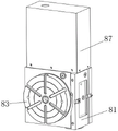
进一步,所述的摆动座8包括固定箱体81、摆动转轴82、转盘83、涡轮84、蜗杆85、摆动电机86,所述的摆动转轴82通过轴承安装在固定箱体81内,转盘83固定安装在摆动转轴82的前端,涡轮84安装在摆动转轴82中部,蜗杆85通过轴承安装在固定箱体81内,涡轮84与蜗杆85相啮合传动,摆动电机86安装在固定箱体81顶部,摆动电机86与蜗杆85通过齿轮传动。Further, the swing seat 8 includes a
进一步,所述的摆动电机86上罩设有防护罩87,防护罩87通过螺钉安装在固定箱体81上。Further, the
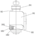
进一步,所述的钻铣主轴箱9包括安装套91、轴套92、钻铣轴93、带轮94、钻铣电机,所述的安装套91通过侧部连接盘安装在摆动座8上,轴套92安装在安装套91内,钻铣轴93通过轴承安装在轴套92内,带轮94安装在钻铣轴93顶部,钻铣电机安装在安装套91上,并与带轮94传动连接。Further, the drilling and
进一步,所述的抱死装置10包括安装座101、抱死块102、液压油缸103,所述的安装座101与安装套91同轴并安装在安装套91底部,安装座101内沿圆周方向均匀开设有滑槽104,抱死块102可滑动嵌装在滑槽104内,抱死块102前端设有与钻铣轴93外壁相匹配的弧形抱死口105,液压油缸103两端分别连接在抱死块102后端和滑槽104后壁上。Further, the
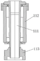
进一步,所述的直立主轴箱11包括直立轴111、主轴套112、皮带轮113,所述的直立轴111通过轴承轴向限位安装在主轴套112内,皮带轮113安装在直立轴111底端,皮带轮113与驱动电机12传动连接,主轴套112两端与直立轴111间通过端盖和密封圈密封安装,直立主轴箱11顶端安装有平旋盘。Further, the
进一步,所述的车床机架1台面为方便排屑倾斜设置,台面上设有排屑口13,排屑口13下方设有储屑仓14,储屑仓14侧壁上设有观察和排料的排料窗口15。Further, the table top of the lathe frame 1 is inclined to facilitate chip removal, and a
本发明的有益效果:Beneficial effects of the present invention:
本发明具有车、铣、钻等多种加工功能,通过平旋盘装夹零部件,BT刀柄夹持各类刀具进行相应加工,结构布局合理,一次装夹能够,能够完成多种加工工序,无需多次搬运、装夹零部件,定位精度高,有利于提高加工精度,提高零部件合格率;操作方便、灵活、装夹简单,有利于降低工人的劳动强度,提高工作效率,并具备五轴五联动功能,可以实现复杂零件加工。The present invention has multiple processing functions such as turning, milling, drilling, etc. The parts are clamped by the flat rotary table, and various types of tools are clamped by the BT handle for corresponding processing. The structure layout is reasonable, and one clamping can complete various processing procedures , without multiple handling and clamping of parts, high positioning accuracy, which is conducive to improving processing accuracy and improving the qualified rate of parts; convenient and flexible operation, simple clamping, is conducive to reducing labor intensity of workers, improving work efficiency, and has The five-axis and five-linkage function can realize complex parts processing.
附图说明Description of drawings
图1是本发明立体示意图。Fig. 1 is a schematic perspective view of the present invention.
图2是本发明摆动座立体示意图。Fig. 2 is a three-dimensional schematic view of the swing seat of the present invention.
图3是本发明摆动座内部结构立体示意图。Fig. 3 is a three-dimensional schematic diagram of the internal structure of the swing seat of the present invention.
图4是本发明钻铣主轴箱和抱死装置立体示意图。Fig. 4 is a three-dimensional schematic view of the drilling and milling headstock and the locking device of the present invention.
图5是本发明钻铣主轴箱和抱死装置局部剖示意图。Fig. 5 is a partial sectional view of the drilling and milling headstock and the locking device of the present invention.
图6是本发明抱死装置内部结构立体示意图。Fig. 6 is a three-dimensional schematic view of the internal structure of the locking device of the present invention.
图7是本发明直立主轴箱全剖示意图。Fig. 7 is a full sectional view of the vertical headstock of the present invention.
具体实施方式Detailed ways
为了使本发明的目的、技术方案和有益效果更加清楚,下面将结合附图,对本发明的优选实施例进行详细的说明,以方便技术人员理解。In order to make the purpose, technical solutions and beneficial effects of the present invention more clear, the preferred embodiments of the present invention will be described in detail below in conjunction with the accompanying drawings, so as to facilitate the understanding of technical personnel.
本发明公开了一种车、铣复合式数控机床,所述的一种车、铣复合式数控机床主要包括车床机架1、直立主轴箱11、驱动电机12、X轴丝杠导轨副2、滑块3、Y轴丝杠导轨副4、支撑臂5、Z轴丝杠导轨副6、滑板7、钻铣主轴箱9、抱死装置10、BT刀柄,所述的直立主轴箱11直立安装在车床机架1台面上,驱动电机12安装在车床机架1上,并与直立主轴箱11传动连接,直立主轴箱11顶部安装有平旋盘,X轴丝杠导轨副2安装在车床机架1上,滑块3安装在X轴丝杠导轨副2上,Y轴丝杠导轨副4安装在滑块3上,支撑臂5安装在Y轴丝杠导轨副4上,Z轴丝杠导轨副6安装在支撑臂5上,滑板7安装在Z轴丝杠导轨副6上,钻铣主轴箱9安装在滑板7上,抱死装置10安装在钻铣主轴箱9上,BT刀柄安装在钻铣主轴箱9底部,BT刀柄能够满足车刀、铣刀和钻刀等多种刀具的装夹,当车削加工时,抱死装置10抱死钻铣主轴体,避免刀具转动,直立主轴箱11驱动零部件转动,通过X轴丝杠导轨副2、Y轴丝杠导轨副4和Z轴丝杠导轨副6的移动实现对零部件的车加工;当进行铣或钻孔工作时,直立主轴箱11和驱动电机12不工作,零部件保持静止,抱死装置10松开钻铣主轴体,通过X轴丝杠导轨副2、Y轴丝杠导轨副4和Z轴丝杠导轨副6的移动实现对零部件的铣加工或钻孔加工;具有车、铣、钻等多种加工功能,通过平旋盘装夹零部件,BT刀柄夹持各类刀具进行相应加工,结构布局合理,一次装夹能够,能够完成多种加工工序,定位精度高,有利于提高加工精度,提高零部件合格率;操作方便、灵活、装夹简单,有利于降低工人的劳动强度,提高工作效率,并具备五轴五联动功能,可以实现复杂零件加工。The invention discloses a turning-milling compound numerical control machine tool. The turning-milling compound numerical control machine tool mainly comprises a lathe frame 1, an
所述的钻铣主轴箱9通过摆动座8安装在滑板7上,所述的摆动座8安装在滑板7上,钻铣主轴箱9安装在摆动座8上,通过摆动座8驱动摆动进行曲面的铣加工(如壳体曲面或风扇的扇叶)。The drilling and
所述的摆动座8包括固定箱体81、摆动转轴82、转盘83、涡轮84、蜗杆85、摆动电机86,所述的摆动转轴82通过轴承安装在固定箱体81内,转盘83固定安装在摆动转轴82的前端,涡轮84安装在摆动转轴82中部,蜗杆85通过轴承安装在固定箱体81内,涡轮84与蜗杆85相啮合传动,摆动电机86安装在固定箱体81顶部,摆动电机86与蜗杆85通过齿轮传动;通过摆动电机86带动蜗杆85转动,传动到涡轮84,从而驱动摆动转轴82和转盘83转动,在加工曲面时,通过摆动电机86驱动摆动转轴82和转盘83往复转动,实现钻铣主轴箱9的往复摆动,满足曲面加工要求。The swing seat 8 includes a
所述的摆动电机86上罩设有防护罩87,防护罩87通过螺钉安装在固定箱体81上。The
所述的钻铣主轴箱9包括安装套91、轴套92、钻铣轴93、带轮94、钻铣电机,所述的安装套91通过侧部连接盘安装在摆动座8上,轴套92安装在安装套91内,钻铣轴93通过轴承安装在轴套92内,带轮94安装在钻铣轴93顶部,钻铣电机安装在安装套91上,并与带轮94传动连接。The drilling and
所述的抱死装置10包括安装座101、抱死块102、液压油缸103,所述的安装座101与安装套91同轴并安装在安装套91底部,安装座101内沿圆周方向均匀开设有滑槽104,抱死块102可滑动嵌装在滑槽104内,抱死块102前端设有与钻铣轴93外壁相匹配的弧形抱死口105,液压油缸103两端分别连接在抱死块102后端和滑槽104后壁上;通过液压油缸103推拉抱死块102实现对钻铣轴93的抱死或松开,结构简单,工作可靠。The
所述的直立主轴箱11包括直立轴111、主轴套112、皮带轮113,所述的直立轴111通过轴承轴向限位安装在主轴套112内,皮带轮113安装在直立轴111底端,皮带轮113与驱动电机12传动连接,主轴套112两端与直立轴111间通过端盖和密封圈密封安装,直立主轴箱11顶端安装有平旋盘。The
所述的车床机架1台面为方便排屑倾斜设置,台面上设有排屑口13,排屑口13下方设有储屑仓14,储屑仓14侧壁上设有观察和排料的排料窗口15。The table top of the lathe frame 1 is tilted for convenience of chip removal, a
工作过程work process
通过BT刀柄能够满足车刀、铣刀和钻刀等多种刀具的装夹,当车削加工时,将零部件装夹在平旋盘上,BT刀柄上装夹上对应的车刀,抱死装置10抱死钻铣主轴体,避免刀具转动,直立主轴箱11驱动零部件转动,通过X轴丝杠导轨副2、Y轴丝杠导轨副4和Z轴丝杠导轨副6的移动实现对零部件的车加工;当进行铣或钻孔工作时,直立主轴箱11和驱动电机12不工作,零部件保持静止,抱死装置10松开钻铣主轴体,BT刀柄上换装上对应的铣刀或钻头,通过X轴丝杠导轨副2、Y轴丝杠导轨副4和Z轴丝杠导轨副6的移动实现对零部件的铣加工或钻孔加工;具有车、铣、钻等多种加工功能,通过平旋盘装夹零部件,BT刀柄夹持各类刀具进行相应加工,结构布局合理,一次装夹能够,能够完成多种加工工序,无需多次搬运、装夹零部件,定位精度高,有利于提高加工精度,提高零部件合格率;操作方便、灵活、装夹简单,有利于降低工人的劳动强度,提高工作效率。The BT tool holder can meet the clamping of various tools such as turning tools, milling cutters and drilling tools. The
最后说明的是,以上优选实施例仅用以说明本发明的技术方案而非限制,尽管通过上述优选实施例已经对本发明进行了详细的描述,但本领域技术人员应当理解,可以在形式上和细节上对其作出各种各样的改变,而不偏离本发明权利要求书所限定的范围。Finally, it should be noted that the above preferred embodiments are only used to illustrate the technical solutions of the present invention and not to limit them. Although the present invention has been described in detail through the above preferred embodiments, those skilled in the art should understand that it can be described in terms of form and Various changes may be made in the details without departing from the scope of the invention defined by the claims.
Claims (8)
Priority Applications (1)
| Application Number | Priority Date | Filing Date | Title |
|---|---|---|---|
| CN202211011487.4A CN115351547A (en) | 2022-08-23 | 2022-08-23 | Turning and milling combined type numerical control machine tool |
Applications Claiming Priority (1)
| Application Number | Priority Date | Filing Date | Title |
|---|---|---|---|
| CN202211011487.4A CN115351547A (en) | 2022-08-23 | 2022-08-23 | Turning and milling combined type numerical control machine tool |
Publications (1)
| Publication Number | Publication Date |
|---|---|
| CN115351547A true CN115351547A (en) | 2022-11-18 |
Family
ID=84003229
Family Applications (1)
| Application Number | Title | Priority Date | Filing Date |
|---|---|---|---|
| CN202211011487.4A Pending CN115351547A (en) | 2022-08-23 | 2022-08-23 | Turning and milling combined type numerical control machine tool |
Country Status (1)
| Country | Link |
|---|---|
| CN (1) | CN115351547A (en) |
Citations (7)
| Publication number | Priority date | Publication date | Assignee | Title |
|---|---|---|---|---|
| CN202088035U (en) * | 2011-05-11 | 2011-12-28 | 宁波耀发数控机床制造有限公司 | Scale division high-speed drilling and milling device of turning machine |
| CN103962872A (en) * | 2014-04-04 | 2014-08-06 | 群基精密工业(苏州)有限公司 | Four-axis machine tool |
| CN203993108U (en) * | 2014-06-10 | 2014-12-10 | 重庆宏钢数控机床有限公司 | Turnning and milling compound lathe |
| CN206241629U (en) * | 2016-12-19 | 2017-06-13 | 广州市佳速精密机械有限公司 | A kind of vertical turn-milling complex machining center structure |
| CN206869441U (en) * | 2017-07-12 | 2018-01-12 | 深圳市钛吉多轴数控机床有限公司 | Vertical shaft class milling-lathe machining center |
| DE102016125307A1 (en) * | 2016-12-22 | 2018-06-28 | Ya Gui | The headstock structure of the CNC milling and drilling machine |
| CN108453507A (en) * | 2018-04-10 | 2018-08-28 | 常州机电职业技术学院 | Drilling and milling device for turning |
-
2022
- 2022-08-23 CN CN202211011487.4A patent/CN115351547A/en active Pending
Patent Citations (7)
| Publication number | Priority date | Publication date | Assignee | Title |
|---|---|---|---|---|
| CN202088035U (en) * | 2011-05-11 | 2011-12-28 | 宁波耀发数控机床制造有限公司 | Scale division high-speed drilling and milling device of turning machine |
| CN103962872A (en) * | 2014-04-04 | 2014-08-06 | 群基精密工业(苏州)有限公司 | Four-axis machine tool |
| CN203993108U (en) * | 2014-06-10 | 2014-12-10 | 重庆宏钢数控机床有限公司 | Turnning and milling compound lathe |
| CN206241629U (en) * | 2016-12-19 | 2017-06-13 | 广州市佳速精密机械有限公司 | A kind of vertical turn-milling complex machining center structure |
| DE102016125307A1 (en) * | 2016-12-22 | 2018-06-28 | Ya Gui | The headstock structure of the CNC milling and drilling machine |
| CN206869441U (en) * | 2017-07-12 | 2018-01-12 | 深圳市钛吉多轴数控机床有限公司 | Vertical shaft class milling-lathe machining center |
| CN108453507A (en) * | 2018-04-10 | 2018-08-28 | 常州机电职业技术学院 | Drilling and milling device for turning |
Similar Documents
| Publication | Publication Date | Title |
|---|---|---|
| CN111037295B (en) | Turning and milling combined machining center | |
| CN209319230U (en) | An automatic processing machine tool with a material transfer manipulator | |
| CN101518879A (en) | Machine tool radial feed system | |
| CN210731032U (en) | Y-axis turret machine | |
| CN216681118U (en) | Vertical car of diaxon line rail grinds all-in-one | |
| CN114406869B (en) | A robotic arm end effector with dual tool switching function | |
| CN109176052B (en) | Automatic machine tool with B-axis control | |
| CN114918669A (en) | Industrial small nine-axis five-link turning and milling compound machine tool | |
| CN211728271U (en) | A new type of CNC automatic lathe | |
| CN211000684U (en) | Five-axis linkage type numerical control engraving machine | |
| CN115351547A (en) | Turning and milling combined type numerical control machine tool | |
| CN217776202U (en) | Mobile double-spindle numerical control turning, milling and drilling composite machine tool | |
| CN219581719U (en) | Inclined hole drilling mechanism of numerical control drilling machine | |
| CN117961581A (en) | Five-axis numerical control turntable | |
| CN217965797U (en) | Turning and milling combined machining device | |
| CN218192652U (en) | Multi-axis numerical control drilling machine | |
| CN217750339U (en) | Turning and milling combined type numerical control machine tool | |
| CN209953823U (en) | Rotary locking device for main shaft of machining center | |
| CN116787229A (en) | Multifunctional turning, milling and grinding composite machining center | |
| CN118528063A (en) | Multi-station numerical control composite machining tool | |
| CN213916109U (en) | Reaming device of variable-frequency electric drive lathe tool | |
| CN223057175U (en) | Five-axis linkage turning and milling compound machine tool with workpiece rotationally positioned in two directions | |
| CN221135062U (en) | Expansion device for machining range of boring and milling machine | |
| CN222711477U (en) | A double-end horizontal processing equipment | |
| CN222660177U (en) | Gantry machine tool for machining double main shafts |
Legal Events
| Date | Code | Title | Description |
|---|---|---|---|
| PB01 | Publication | ||
| PB01 | Publication | ||
| SE01 | Entry into force of request for substantive examination | ||
| SE01 | Entry into force of request for substantive examination | ||
| RJ01 | Rejection of invention patent application after publication | ||
| RJ01 | Rejection of invention patent application after publication |
Application publication date: 20221118 |