CN115105359A - Limb joint flexion and extension device with good wrapping comfort for rehabilitation nursing - Google Patents
Limb joint flexion and extension device with good wrapping comfort for rehabilitation nursing Download PDFInfo
- Publication number
- CN115105359A CN115105359A CN202210749623.3A CN202210749623A CN115105359A CN 115105359 A CN115105359 A CN 115105359A CN 202210749623 A CN202210749623 A CN 202210749623A CN 115105359 A CN115105359 A CN 115105359A
- Authority
- CN
- China
- Prior art keywords
- fixedly connected
- plate
- rod
- arc
- comfort
- Prior art date
- Legal status (The legal status is an assumption and is not a legal conclusion. Google has not performed a legal analysis and makes no representation as to the accuracy of the status listed.)
- Withdrawn
Links
Images


Classifications
-
- A—HUMAN NECESSITIES
- A61—MEDICAL OR VETERINARY SCIENCE; HYGIENE
- A61H—PHYSICAL THERAPY APPARATUS, e.g. DEVICES FOR LOCATING OR STIMULATING REFLEX POINTS IN THE BODY; ARTIFICIAL RESPIRATION; MASSAGE; BATHING DEVICES FOR SPECIAL THERAPEUTIC OR HYGIENIC PURPOSES OR SPECIFIC PARTS OF THE BODY
- A61H1/00—Apparatus for passive exercising; Vibrating apparatus ; Chiropractic devices, e.g. body impacting devices, external devices for briefly extending or aligning unbroken bones
- A61H1/02—Stretching or bending or torsioning apparatus for exercising
- A61H1/0237—Stretching or bending or torsioning apparatus for exercising for the lower limbs
-
- A—HUMAN NECESSITIES
- A61—MEDICAL OR VETERINARY SCIENCE; HYGIENE
- A61H—PHYSICAL THERAPY APPARATUS, e.g. DEVICES FOR LOCATING OR STIMULATING REFLEX POINTS IN THE BODY; ARTIFICIAL RESPIRATION; MASSAGE; BATHING DEVICES FOR SPECIAL THERAPEUTIC OR HYGIENIC PURPOSES OR SPECIFIC PARTS OF THE BODY
- A61H2201/00—Characteristics of apparatus not provided for in the preceding codes
- A61H2201/01—Constructive details
- A61H2201/0119—Support for the device
- A61H2201/0138—Support for the device incorporated in furniture
- A61H2201/0142—Beds
-
- A—HUMAN NECESSITIES
- A61—MEDICAL OR VETERINARY SCIENCE; HYGIENE
- A61H—PHYSICAL THERAPY APPARATUS, e.g. DEVICES FOR LOCATING OR STIMULATING REFLEX POINTS IN THE BODY; ARTIFICIAL RESPIRATION; MASSAGE; BATHING DEVICES FOR SPECIAL THERAPEUTIC OR HYGIENIC PURPOSES OR SPECIFIC PARTS OF THE BODY
- A61H2201/00—Characteristics of apparatus not provided for in the preceding codes
- A61H2201/12—Driving means
- A61H2201/1207—Driving means with electric or magnetic drive
-
- A—HUMAN NECESSITIES
- A61—MEDICAL OR VETERINARY SCIENCE; HYGIENE
- A61H—PHYSICAL THERAPY APPARATUS, e.g. DEVICES FOR LOCATING OR STIMULATING REFLEX POINTS IN THE BODY; ARTIFICIAL RESPIRATION; MASSAGE; BATHING DEVICES FOR SPECIAL THERAPEUTIC OR HYGIENIC PURPOSES OR SPECIFIC PARTS OF THE BODY
- A61H2201/00—Characteristics of apparatus not provided for in the preceding codes
- A61H2201/16—Physical interface with patient
- A61H2201/1602—Physical interface with patient kind of interface, e.g. head rest, knee support or lumbar support
- A61H2201/164—Feet or leg, e.g. pedal
- A61H2201/1642—Holding means therefor
-
- A—HUMAN NECESSITIES
- A61—MEDICAL OR VETERINARY SCIENCE; HYGIENE
- A61H—PHYSICAL THERAPY APPARATUS, e.g. DEVICES FOR LOCATING OR STIMULATING REFLEX POINTS IN THE BODY; ARTIFICIAL RESPIRATION; MASSAGE; BATHING DEVICES FOR SPECIAL THERAPEUTIC OR HYGIENIC PURPOSES OR SPECIFIC PARTS OF THE BODY
- A61H2201/00—Characteristics of apparatus not provided for in the preceding codes
- A61H2201/16—Physical interface with patient
- A61H2201/1602—Physical interface with patient kind of interface, e.g. head rest, knee support or lumbar support
- A61H2201/1654—Layer between the skin and massage elements, e.g. fluid or ball
Abstract
The invention provides a limb joint flexion and extension device with good wrapping comfort for rehabilitation nursing, and relates to the technical field of medical devices. This recovered nursing is with limbs joint device of stretching that bends with good parcel travelling comfort, including bedstead and mount, mount fixed connection is in the bedstead top, the inside fixedly connected with fixed plate of mount, fixed plate one side articulates there are two thigh backup pads, two thigh backup pad one side all articulates there is the shank backup pad, two fixing boxes of the inside fixedly connected with of bedstead, the inside rotation of fixing box is connected with first threaded rod. This recovered nursing with limbs joint is bent and is stretched device with good parcel travelling comfort for blood circulation carries out the training aiding to the patient that can't independently lift the leg, covers patient's shank, is favorable to supporting the shank, prevents to remove when the training, improves the security, improves the travelling comfort to adapt to different physique crowds.
Description
Technical Field
The invention relates to a nursing device, in particular to a limb joint flexion and extension device with good wrapping comfort for rehabilitation nursing, and belongs to the technical field of medical devices.
Background
In long-term clinical practice, most patients in neurology are accompanied by acroparalysis, and are often treated by a massage method, particularly legs, so that a plurality of massagers are available on the market at present, the labor intensity of medical staff is greatly reduced, the working efficiency of the medical staff is improved, and meanwhile, a certain effect is brought to the treatment of the patients. However, there is a problem that the degree of movement of the limb joints is an important index for rehabilitation in addition to passive muscle massage, and in order to prevent joint contracture and deformation, the knee joint needs to be subjected to flexion and extension movements while the leg is massaged, so that the flexion and extension movements of the knee joint can improve the therapeutic effect.
But when bending and stretching rehabilitation training is carried out to patient's shank among the prior art, most of them are through medical personnel manual with patient's shank lift up, need consume a large amount of physical power, and present most of medical personnel are the women, physical power is male sex originally just not dominant, the degree of difficulty is great when the operation, work efficiency is low, long-time work back physical strength is simply weak and probably causes the patient injury, there is great potential safety hazard, and patient's comfort level is lower, it is less to the recovered effect of patient training, be unfavorable for the use.
Disclosure of Invention
Technical problem to be solved
The invention aims to solve the problems that in the prior art, when the leg of a patient is subjected to flexion-extension rehabilitation training, most of the medical staff manually lift the leg of the patient, a large amount of physical strength is required to be consumed, most of the medical staff are female, the physical strength is not superior to that of male, the difficulty is high during operation, the working efficiency is low, the patient is likely to be injured due to insufficient physical strength after long-time work, the potential safety hazard is high, the comfort level of the patient is low, the rehabilitation effect on the patient training is small, and the use is not facilitated.
(II) technical scheme
In order to achieve the purpose, the invention is realized by the following technical scheme: the limb joint flexion and extension device with good wrapping comfort for rehabilitation nursing comprises a bedstead and a fixing frame, wherein the fixing frame is fixedly connected to the top of the bedstead, a fixing plate is fixedly connected inside the fixing frame, two thigh supporting plates are hinged to one side of the fixing plate, two shank supporting plates are hinged to one side of the two thigh supporting plates, two fixing boxes are fixedly connected inside the bedstead, a first threaded rod is rotatably connected inside the fixing boxes, one end of the first threaded rod is fixedly connected with a second threaded rod, the outer side of the second threaded rod is in threaded connection with a moving block, the top of the moving block is fixedly connected with a toothed plate, one end side edge of each thigh supporting plate is fixedly connected with a supporting rod, the outer side of each supporting rod is fixedly connected with a half gear, the half gear is meshed with the toothed plate and connected with a moving seat, the outer side of the first threaded rod is in threaded connection with a moving seat, and one side of the top of the moving seat is fixedly connected with a hinging block, one side of the hinge block is hinged with a support rod, one end of the support rod is fixedly connected with an electric push rod, the output end of the electric push rod is fixedly connected with a push rod, the bottom of the shank support plate is fixedly connected with a hinge plate, and the push rod is hinged with the hinge plate;
the novel crus supporting plate is characterized in that arc-shaped plates are arranged on two sides of the crus supporting plate, the arc-shaped plates are arranged oppositely, one ends of the arc-shaped plates are fixedly connected with arc sleeves, arc-shaped racks are fixedly connected inside the arc sleeves, one ends of the crus supporting plate are rotatably connected with rotating rods, transmission gears are fixedly connected to the outer sides of the rotating rods, and the transmission gears are meshed with the arc-shaped racks and connected with the rotating rods.
Preferably, arc bottom fixedly connected with gasbag, gasbag outside fixedly connected with supports the cover, is favorable to supporting the gasbag, prevents to drop, support cover bottom fixedly connected with ventilation net, make the gasbag aerify the inflation messenger support the ventilation net to make ventilation net and patient's shank laminating, improve the parcel nature, increase the comfort level, a plurality of air vents have been seted up to ventilation net inside, are favorable to dispelling the heat, prevent that patient's shank from perspiring more.
Preferably, gasbag one end fixedly connected with connector, arc top fixedly connected with inflator, inflator one end fixedly connected with communicating pipe, communicating pipe one end fixedly connected with breather pipe, the breather pipe run through the arc and with arc fixed connection, arc bottom and connector fixed connection make the inflator to the inside output gas of communicating pipe to aerify the gasbag through the breather pipe, make the gasbag inflation.
Preferably, the inside sliding connection of inflator has the piston, the piston outside cover is equipped with the sealing washer, piston top fixedly connected with push rod, the push rod run through the inflator and with inflator sliding connection, make the push rod remove and drive the piston and remove to aerify.
Preferably, one end of the push rod is fixedly connected with a push plate, one side of the push plate is fixedly connected with a support plate, the support plate is internally and slidably connected with a press rod, the top end of the press rod is fixedly connected with a pulling plate, the outer side of the press rod is fixedly connected with a transverse plate, the top of the transverse plate is fixedly connected with a spring, the spring is sleeved on the outer side of the press rod, the bottom end of the press rod is fixedly connected with a clamping rod, the top of the arc plate is fixedly connected with a limiting clamping plate, a plurality of limiting clamping grooves are formed in the limiting clamping plate, the clamping rod is respectively matched with the limiting clamping grooves, the pulling plate drives the press rod to ascend, the press rod drives the transverse plate to move, the transverse plate compresses the spring, the clamping rod ascends, the clamping rod is separated from clamping connection with the limiting clamping plate, the push rod is pushed to drive the push rod to move, the clamping rod is driven to move, the pulling plate is loosened, and the spring pushes the transverse plate to descend, thereby drive depression bar and joint pole decline and spacing cardboard and carry out the joint, carry out spacingly to the push rod.
Preferably, the inside one end fixedly connected with riser of shank backup pad, the bull stick runs through the riser and rotates with the riser and be connected, bull stick one end fixedly connected with worm wheel, the meshing of worm wheel bottom is connected with the worm, the worm runs through shank backup pad lateral wall and rotates with the shank backup pad to be connected, the worm extends to shank backup pad outside one end fixedly connected with knob, rotates the knob and drives the worm and rotate to drive the worm wheel and rotate, the worm wheel drives bull stick and drive gear and rotates, drives the arc rack and removes.
Preferably, two fixed boxes of inside fixedly connected with of thigh backup pad, the inside fixedly connected with locating lever of fixed box, locating lever outside fixedly connected with spring, spring one end fixedly connected with bandage, bandage one end fixedly connected with dog, logical groove has been seted up to fixed box top one side, the bandage runs through logical groove and with fixed box sliding connection, the dog sets up in the fixed box outside, two dops of thigh backup pad top opposite side fixedly connected with, the bandage respectively with a plurality of dop looks adaptations is favorable to making the bandage pass the dop and tie up patient's thigh and tie up, improves stability.
Preferably, the fixed box is fixedly connected with a motor, the motor output end is fixedly connected with a first threaded rod, the fixed box is fixedly connected with a connecting plate, one side of the connecting plate is fixedly connected with a limiting rod, the bottom of the moving block is fixedly connected with a limiting block, and the limiting rod penetrates through the limiting block and is in sliding connection with the limiting block.
Preferably, the fixed plate opposite side articulates there is the jacking board, the inside one side of bedstead articulates there is the pneumatic cylinder, the pneumatic cylinder output is articulated with jacking board bottom one side, the inside both sides of jacking board all articulate there is the curb plate, curb plate top one side fixedly connected with handle, handle one side fixedly connected with controller, electric putter, pneumatic cylinder and motor all with controller electric connection, be favorable to the patient to control convenient and fast.
Preferably, the massage pad is fixedly connected to the top of the crus supporting plate, and the protective pad is fixedly connected to one side of the arc plate, so that the protective effect is improved, and the legs are protected.
The invention provides a limb joint flexion and extension device with good wrapping comfort for rehabilitation nursing, which has the following beneficial effects:
1. the limb joint bending and stretching device for rehabilitation nursing with good wrapping comfort drives a first threaded rod to rotate by starting a motor, the first threaded rod drives a second threaded rod to rotate, the second threaded rod drives a moving block to move when rotating, the moving block moves to drive a toothed plate to move, the toothed plate moves to drive a half gear to rotate, the half gear drives a supporting rod to rotate when rotating, so as to drive a thigh supporting plate to deflect, meanwhile, the moving seat moves when rotating, the moving seat moves to drive a hinge block to move, the hinge block moves to drive a supporting rod to move, so that an electric push rod moves, the electric push rod pushes the ejector rod to move, the ejector rod pushes a shank supporting plate to lift the shank supporting plate upwards, so that the thigh supporting plate and the shank supporting plate are mutually matched to lift thighs and shanks of a patient upwards, and the electric push rod can start to push the ejector rod and the hinged plate to move, so that the lower leg supporting plate is driven to ascend and descend, the lower leg of the patient is controlled to conduct flexion and extension training, the leg of the patient is supported, blood circulation is accelerated, and auxiliary training is conducted on the patient who cannot lift the leg independently.
2. This device is bent and stretched with limbs joint to rehabilitation nursing with good parcel travelling comfort, it rotates to drive the worm through manual rotation knob of manual medical personnel, the worm rotates and drives the worm wheel and rotate, it rotates to drive the bull stick when the worm wheel rotates, the bull stick rotates and drives drive gear and rotate, make drive gear rotate and drive the arc rack and remove, thereby make the arc rack drive the arc cover and remove, arc cover and arc fixed connection, make the arc cover drive the arc and remove, and two arcs are close to the laminating each other, cover patient's shank, be favorable to supporting the shank, prevent to remove when the training, the security is improved.
3. This device is bent and stretched with limbs joint to rehabilitation nursing with good parcel travelling comfort, it is spacing to carry out through the push rod, the piston removes the inside gaseous outside discharge of inflator, and make gaseous discharging through communicating pipe and breather pipe, make gaseous inside the connector entering gasbag, make the gasbag outwards expand, thereby drive and support the cover and the net that ventilates and remove, thereby make the net of ventilating and patient's shank laminating, provide good cladding nature to the shank, reinforcing patient's comfort level, alleviate muscle pressure, improve recovered effect, and ventilate the net and set up to the fretwork type, a plurality of air vents have been seted up to inside, be favorable to giving off the heat, reduce patient's stifle sensation, the comfort is improved, and adapt to different physique crowds.
4. This recovered nursing with limbs joint device of stretching that bends with good parcel travelling comfort, through finishing the back to the shank cladding, pull out the dog and drive bandage and coil spring and stretch to drive the bandage laminating and patient's thigh outside, make the dog pass the dop after that, make the dop drive the bandage with oneself back adhesion, thereby carry out spacing support, improvement stability to patient's thigh.
Drawings
FIG. 1 is a schematic view of the overall structure of the present invention;
FIG. 2 is a schematic view of the working state of the present invention;
FIG. 3 is a side cross-sectional view of the present invention;
FIG. 4 is an enlarged view of the portion A of FIG. 3 according to the present invention.
FIG. 5 is an enlarged view of the portion B of FIG. 3 according to the present invention;
FIG. 6 is an enlarged view of the structure of the portion C of FIG. 3 according to the present invention;
FIG. 7 is an enlarged view of the portion D of FIG. 3 according to the present invention;
FIG. 8 is an enlarged view of the portion E of FIG. 3 according to the present invention;
FIG. 9 is a schematic structural view of a movable base according to the present invention;
FIG. 10 is a schematic view of the electric putter of the present invention;
FIG. 11 is a schematic view of the construction of an arcuate rack of the present invention;
FIG. 12 is a front cross-sectional view of a cartridge in accordance with the present invention;
FIG. 13 is a schematic view of the compression bar of the present invention;
FIG. 14 is a schematic structural view of a spacing clip of the present invention;
fig. 15 is a front sectional view of the fixing box of the present invention.
In the figure: 1. a bed frame; 2. a fixed mount; 3. a fixing plate; 4. a fixed box; 5. a thigh support plate; 6. a shank support plate; 7. a first threaded rod; 8. a second threaded rod; 9. a moving block; 10. a toothed plate; 11. a strut; 12. a half gear; 13. a movable seat; 14. a hinged block; 15. a support bar; 16. an electric push rod; 17. a top rod; 18. a hinge plate; 19. a connecting plate; 20. a limiting rod; 21. a limiting block; 22. an arc-shaped plate; 23. an arc-shaped sleeve; 24. an arc-shaped rack; 25. a rotating rod; 26. a transmission gear; 27. an air bag; 28. a support sleeve; 29. a ventilation net; 30. a vent hole; 31. a connector; 32. an air cylinder; 33. a communicating pipe; 34. a breather pipe; 35. a push rod; 36. a piston; 37. pushing the plate; 38. a support plate; 39. a pressure lever; 40. a spring; 41. a transverse plate; 42. a clamping and connecting rod; 43. pulling a plate; 44. a limiting clamping plate; 45. a limiting clamping groove; 46. a vertical plate; 47. a worm gear; 48. a worm; 49. a fixing box; 50. positioning a rod; 51. a coil spring; 52. binding bands; 53. a stopper; 54. clamping a head; 55. a jacking plate; 56. a hydraulic cylinder; 57. a side plate; 58. a handle; 59. an electric motor.
Detailed Description
The embodiment of the invention provides a limb joint flexion and extension device with good wrapping comfort for rehabilitation nursing.
Referring to fig. 1, 2, 3, 4, 5, 9 and 10, the bed comprises a bed frame 1 and a fixed frame 2, the fixed frame 2 is fixedly connected to the top of the bed frame 1, a fixed plate 3 is fixedly connected to the inside of the fixed frame 2, two thigh supporting plates 5 are hinged to one side of the fixed plate 3, a shank supporting plate 6 is hinged to one side of each thigh supporting plate 5, two fixed boxes 4 are fixedly connected to the inside of the bed frame 1, a first threaded rod 7 is rotatably connected to the inside of each fixed box 4, a second threaded rod 8 is fixedly connected to one end of each first threaded rod 7, a moving block 9 is connected to the outside of each second threaded rod 8 through a thread, a toothed plate 10 is fixedly connected to the top of each moving block 9, a supporting rod 11 is fixedly connected to the side edge of one end of each thigh supporting plate 5, a half gear 12 is fixedly connected to the outside of each supporting rod 11, the half gear 12 is engaged with the toothed plate 10, a moving seat 13 is connected to the outside of each first threaded rod 7 through a thread, remove articulated piece 14 of base 13 top one side fixedly connected with, articulated piece 14 one side articulates there is the bracing piece 15, bracing piece 15 one end fixedly connected with electric putter 16, electric putter 16 output end fixedly connected with ejector pin 17, 6 bottom fixedly connected with articulated slab 18 of shank backup pad, ejector pin 17 articulates with articulated slab 18, the inside fixedly connected with motor 59 of stationary box 4, motor 59 output and first threaded rod 7 fixed connection, the inside fixedly connected with connecting plate 19 of stationary box 4, connecting plate 19 one side fixedly connected with gag lever post 20, movable block 9 bottom fixedly connected with stopper 21, gag lever post 20 run through stopper 21 and with stopper 21 sliding connection.
Specifically, the patient lies on the top of the fixing frame 2, and puts the thighs on the top of the two thigh supporting plates 5, the calves are put on the top of the two calves supporting plates 6, the motor 59 is started to drive the first threaded rod 7 to rotate, the first threaded rod 7 rotates to drive the second threaded rod 8 to rotate, the second threaded rod 8 drives the moving block 9 to move when rotating, the moving block 9 moves to drive the toothed plate 10 to move, the toothed plate 10 moves to drive the half gear 12 to rotate, the half gear 12 rotates to drive the supporting rod 11 to rotate, so as to drive the thigh supporting plates 5 to deflect, meanwhile, the first threaded rod 7 drives the moving seat 13 to move when rotating, the moving seat 13 moves to drive the hinge block 14 to move, the hinge block 14 moves to drive the supporting rod 15 to move, so as to move the electric push rod 16, so as to push the push rod 16 to push the ejector rod 17 to move, so that the ejector rod 17 lifts the calves supporting plates 6 upwards, therefore, the thigh supporting plate 5 and the shank supporting plate 6 are matched with each other to lift the thigh and the shank of the patient upwards, the electric push rod 16 can be started to push the push rod 17 and the hinged plate 18 to move to drive the shank supporting plate 6 to ascend and descend, so that the shank of the patient is controlled to conduct flexion and extension training, the leg of the patient is supported, blood circulation is accelerated, and the auxiliary training is conducted on the patient who cannot lift the leg independently.
Two thigh backup pads 5 and two shank backup pads 6 can the independent control to the leg is distinguished the training about the patient, strong adaptability, and application scope is wider.
Referring to fig. 1, 2, 3, 4, 6, 7, 8, 11, 12, 13 and 14 again, the arc plates 22 are disposed on both sides of the lower leg support plate 6, the two arc plates 22 are disposed opposite to each other, one end of each of the two arc plates 22 is fixedly connected with the arc sleeve 23, the arc rack 24 is fixedly connected inside the arc sleeve 23, one end inside the lower leg support plate 6 is rotatably connected with the rotating rod 25, the outer side of the rotating rod 25 is fixedly connected with the transmission gear 26, the transmission gear 26 is meshed with the arc rack 24, one end inside the lower leg support plate 6 is fixedly connected with the vertical plate 46, the rotating rod 25 penetrates through the vertical plate 46 and is rotatably connected with the vertical plate 46, one end of the rotating rod 25 is fixedly connected with the worm wheel 47, the bottom of the worm wheel 47 is meshed with the worm 48, the worm 48 penetrates through the side wall of the lower leg support plate 6 and is rotatably connected with the lower leg support plate 6, the worm 48 extends to one end outside the lower leg support plate 6 and is fixedly connected with the knob, rotate knob drive worm 48 and rotate, thereby it rotates to drive worm wheel 47, worm wheel 47 drives bull stick 25 and drive gear 26 and rotates, it removes to drive arc rack 24, arc 22 bottom fixedly connected with gasbag 27, gasbag 27 outside fixedly connected with supports cover 28, be favorable to supporting gasbag 27, prevent to drop, support cover 28 bottom fixedly connected with net 29 of ventilating, make gasbag 27 aerify the inflation and make and support net 29 of ventilating, thereby make net 29 of ventilating and patient's shank laminating, improve the parcel nature, increase the comfort level, net 29 of ventilating has seted up a plurality of air vents 30 inside, be favorable to dispelling the heat, it is more to prevent that patient's shank from sweating.
The air bag 27 is fixedly connected with a connector 31 at one end, an air cylinder 32 is fixedly connected with the top of the arc plate 22, a communicating pipe 33 is fixedly connected with one end of the air cylinder 32, a vent pipe 34 is fixedly connected with one end of the communicating pipe 33, the vent pipe 34 penetrates through the arc plate 22 and is fixedly connected with the arc plate 22, the bottom end of the arc plate 22 is fixedly connected with the connector 31, the air cylinder 32 outputs air to the inside of the communicating pipe 33, so that the air bag 27 is inflated through the vent pipe 34, the air bag 27 is expanded, a piston 36 is slidably connected to the inside of the air cylinder 32, a sealing ring is sleeved on the outer side of the piston 36, a push rod 35 is fixedly connected with the top of the piston 36, the push rod 35 penetrates through the air cylinder 32 and is slidably connected with the air cylinder 32, and the push rod 35 moves to drive the piston 36 to move, and accordingly the air is inflated.
One end of the push rod 35 is fixedly connected with a push plate 37, one side of the push plate 37 is fixedly connected with a support plate 38, the interior of the support plate 38 is slidably connected with a press rod 39, the top end of the press rod 39 is fixedly connected with a pulling plate 43, the outer side of the press rod 39 is fixedly connected with a transverse plate 41, the top of the transverse plate 41 is fixedly connected with a spring 40, the spring 40 is sleeved on the outer side of the press rod 39, the bottom end of the press rod 39 is fixedly connected with a clamping rod 42, the top of the arc plate 22 is fixedly connected with a limiting clamping plate 44, a plurality of limiting clamping grooves 45 are formed in the limiting clamping plate 44, the clamping rod 42 is respectively matched with the limiting clamping grooves 45, the pulling plate 43 drives the press rod 39 to ascend, the press rod 39 drives the transverse plate 41 to move, the transverse plate 41 compresses the spring 40, so that the clamping rod 42 ascends, the clamping rod 42 is separated from the clamping with the limiting clamping plate 44, the push plate 37 is driven to drive the push rod 35 to move, thereby driving the clamping rod 42 to move, and the pulling plate 43 to loosen, the spring 40 pushes the transverse plate 41 to descend, so as to drive the pressure rod 39 and the clamping rod 42 to descend and be clamped with the limiting clamping plate 44, and the push rod 35 is limited
Specifically, place after 6 tops in shank backup pad when patient's shank, it rotates to drive worm 48 through manual medical personnel manual rotation knob, worm 48 rotates and drives worm wheel 47 and rotate, it rotates to drive bull stick 25 when worm wheel 47 rotates, bull stick 25 rotates and drives drive gear 26 and rotate, it moves to make drive gear 26 rotate and drive arc rack 24, thereby make arc rack 24 drive arc cover 23 and remove, arc cover 23 and arc 22 fixed connection, make arc cover 23 drive arc 22 and remove, and two arc 22 are close to the laminating each other, cover patient's shank, be favorable to supporting the shank, prevent to remove when the training.
After the primary covering of the leg is finished, the medical staff manually pulls the pulling plate 43 upwards to make the pulling plate 43 drive the pressing rod 39 to rise, the pressing rod 39 drives the transverse plate 41 to extrude the spring 40, thereby driving the clamping rod 42 to rise to be separated from the clamping with the limiting clamping plate 44, then pushes the pushing plate 37 to drive the pushing rod 35 to move, the pushing rod 35 moves to drive the piston 36 to move, when the pushing rod moves to a proper position, the pulling plate 43 is loosened to make the spring 40 drive the transverse plate 41 to fall, the transverse plate 41 drives the pressing rod 39 to fall, thereby enabling the clamping rod 42 to be clamped with the limiting clamping groove 45, limiting is carried out on the pushing rod 35, the piston 36 moves to discharge the gas in the air cylinder 32 outwards, and the gas is discharged through the communicating pipe 33 and the vent pipe 34, so that the gas enters the air bag 27 from the connector 31, the air bag 27 expands outwards, thereby driving the supporting sleeve 28 and the vent net 29 to move, thereby enabling the vent net 29 to be attached to the shank of the patient, provide good cladding nature to the shank, reinforcing patient's comfort level alleviates muscle pressure, improves recovered effect to ventilation net 29 sets up to the fretwork type, and a plurality of air vents 30 have been seted up to inside, is favorable to giving off the heat, reduces patient's stifle sense, improves the travelling comfort, and adapts to different physique crowds.
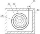
Referring to fig. 1, 2, 3 and 15 again, two fixing boxes 49 are fixedly connected inside the thigh support plate 5, positioning rods 50 are fixedly connected inside the fixing boxes 49, coil springs 51 are fixedly connected to the outer sides of the positioning rods 50, binding bands 52 are fixedly connected to one ends of the coil springs 51, one ends of the binding bands 52 are fixedly connected to stop blocks 53, through grooves are formed in one sides of the tops of the fixing boxes 49, the binding bands 52 penetrate through the through grooves and are in sliding connection with the fixing boxes 49, the stop blocks 53 are arranged on the outer sides of the fixing boxes 49, two clamping heads 54 are fixedly connected to the other sides of the tops of the thigh support plate 5, the binding bands 52 are respectively matched with the clamping heads 54, the binding bands 52 can penetrate through the clamping heads 54, the thighs of patients can be bound, and stability is improved.
Specifically, after the coating of the lower leg is finished, the stop block 53 is pulled out to drive the bandage 52 and the coil spring 51 to stretch, the bandage 52 is driven to be attached to the outer side of the thigh of the patient, then the stop block 53 penetrates through the clamping head 54, and the clamping head 54 drives the bandage 52 to be adhered to the back of the patient, so that the thigh of the patient is limited and supported, and the stability is improved.
Please refer to fig. 1, fig. 2, fig. 3 and fig. 4 again, the other side of the fixing plate 3 is hinged with a lifting plate 55, one side inside the bed frame 1 is hinged with a hydraulic cylinder 56, the output end of the hydraulic cylinder 56 is hinged with one side of the bottom of the lifting plate 55, both sides inside the lifting plate 55 are hinged with side plates 57, one side of the top of the side plate 57 is fixedly connected with a handle 58, one side of the handle 58 is fixedly connected with a controller, the electric push rod 16, the hydraulic cylinder 56 and the motor 59 are electrically connected with the controller, which is beneficial for the patient to control, the operation is convenient and fast, the top of the crus supporting plate 6 is fixedly connected with a massage cushion, one side of the arc plate 22 is fixedly connected with a protection cushion, the protection effect is improved, and the legs are protected.
Specifically, start through pneumatic cylinder 56 and drive jacking board 55 and upwards lift up, be favorable to supporting the patient upper part of the body to the patient can be controlled electric putter 16, pneumatic cylinder 56 and motor 59 through the controller, and the operation of being convenient for improves the convenience.
Claims (10)
1. Device is bent and stretched with limbs joint to rehabilitation care with good parcel travelling comfort, including bedstead (1) and mount (2), mount (2) fixed connection is in bedstead (1) top, its characterized in that: the fixing frame (2) is internally and fixedly connected with a fixing plate (3), one side of the fixing plate (3) is hinged with two thigh supporting plates (5), one side of each thigh supporting plate (5) is hinged with a shank supporting plate (6), the bedstead (1) is internally and fixedly connected with two fixing boxes (4), the fixing boxes (4) are internally and rotatably connected with first threaded rods (7), one ends of the first threaded rods (7) are fixedly connected with second threaded rods (8), the outer sides of the second threaded rods (8) are in threaded connection with moving blocks (9), the tops of the moving blocks (9) are fixedly connected with toothed plates (10), the side edges of one ends of the thigh supporting plates (5) are fixedly connected with supporting rods (11), the outer sides of the supporting rods (11) are fixedly connected with half gears (12), the half gears (12) are in meshed connection with the toothed plates (10), and the outer sides of the first threaded rods (7) are in threaded connection with moving seats (13), one side of the top of the moving seat (13) is fixedly connected with a hinge block (14), one side of the hinge block (14) is hinged with a support rod (15), one end of the support rod (15) is fixedly connected with an electric push rod (16), the output end of the electric push rod (16) is fixedly connected with a push rod (17), the bottom of the shank support plate (6) is fixedly connected with a hinge plate (18), and the push rod (17) is hinged with the hinge plate (18);
shank backup pad (6) both sides all are provided with arc (22), two arc (22) set up relatively, two the equal fixedly connected with arc cover (23) of arc (22) one end, arc cover (23) inside fixedly connected with arc rack (24), the inside one end of shank backup pad (6) is rotated and is connected with bull stick (25), bull stick (25) outside fixedly connected with drive gear (26), drive gear (26) are connected with arc rack (24) meshing.
2. The limb joint flexion and extension device with good wrapping comfort for rehabilitation nursing according to claim 1, characterized in that: the air bag supporting device is characterized in that an air bag (27) is fixedly connected to the bottom of the arc-shaped plate (22), a supporting sleeve (28) is fixedly connected to the outer side of the air bag (27), an air ventilation net (29) is fixedly connected to the bottom of the supporting sleeve (28), and a plurality of air vents (30) are formed in the air ventilation net (29).
3. The limb joint flexion and extension device with good wrapping comfort for rehabilitation nursing according to claim 2, characterized in that: gasbag (27) one end fixedly connected with connector (31), arc (22) top fixedly connected with inflator (32), inflator (32) one end fixedly connected with communicating pipe (33), communicating pipe (33) one end fixedly connected with breather pipe (34), breather pipe (34) run through arc (22) and with arc (22) fixed connection, arc (22) bottom and connector (31) fixed connection.
4. The limb joint flexion and extension device with good wrapping comfort for rehabilitation nursing according to claim 3, characterized in that: inflator (32) inside sliding connection has piston (36), piston (36) outside cover is equipped with the sealing washer, piston (36) top fixedly connected with push rod (35), push rod (35) run through inflator (32) and with inflator (32) sliding connection.
5. The limb joint flexion and extension device with good wrapping comfort for rehabilitation nursing according to claim 4, characterized in that: the improved structure of the arc-shaped plate is characterized in that one end of the push rod (35) is fixedly connected with a push plate (37), one side of the push plate (37) is fixedly connected with a support plate (38), the support plate (38) is internally connected with a press rod (39) in a sliding manner, the top end of the press rod (39) is fixedly connected with a pull plate (43), the outer side of the press rod (39) is fixedly connected with a transverse plate (41), the top of the transverse plate (41) is fixedly connected with a spring (40), the spring (40) is sleeved on the outer side of the press rod (39), the bottom end of the press rod (39) is fixedly connected with a clamping rod (42), the top of the arc-shaped plate (22) is fixedly connected with a limiting clamping plate (44), a plurality of limiting clamping grooves (45) are formed in the limiting clamping plate (44), and the clamping rod (42) is respectively matched with the plurality of limiting clamping grooves (45).
6. The limb joint flexion and extension device with good wrapping comfort for rehabilitation nursing according to claim 1, characterized in that: the inside one end fixedly connected with riser (46) of shank backup pad (6), bull stick (25) run through riser (46) and rotate with riser (46) and be connected, bull stick (25) one end fixedly connected with worm wheel (47), worm wheel (47) bottom meshing is connected with worm (48), worm (48) run through shank backup pad (6) lateral wall and rotate with shank backup pad (6) and be connected, worm (48) extend to shank backup pad (6) outside one end fixedly connected with knob.
7. The limb joint flexion and extension device with good wrapping comfort for rehabilitation nursing according to claim 1, characterized in that: two fixed boxes (49) are fixedly connected with the inside of the thigh supporting plate (5), a positioning rod (50) is fixedly connected with the inside of the fixed box (49), a coil spring (51) is fixedly connected with the outer side of the positioning rod (50), a binding belt (52) is fixedly connected with one end of the coil spring (51), a stop block (53) is fixedly connected with one end of the binding belt (52), a through groove is formed in one side of the top of the fixed box (49), the binding belt (52) penetrates through the through groove and is in sliding connection with the fixed box (49), the stop block (53) is arranged on the outer side of the fixed box (49), two clamping heads (54) are fixedly connected with the other side of the top of the thigh supporting plate (5), and the binding belt (52) is respectively matched with the plurality of clamping heads (54).
8. The limb joint flexion and extension device with good wrapping comfort for rehabilitation nursing according to claim 1, characterized in that: the inner part of the fixed box (4) is fixedly connected with a motor (59), the output end of the motor (59) is fixedly connected with a first threaded rod (7), the inner part of the fixed box (4) is fixedly connected with a connecting plate (19), one side of the connecting plate (19) is fixedly connected with a limiting rod (20), the bottom of the moving block (9) is fixedly connected with a limiting block (21), and the limiting rod (20) penetrates through the limiting block (21) and is in sliding connection with the limiting block (21).
9. The limb joint flexion and extension device with good wrapping comfort for rehabilitation nursing according to claim 8, characterized in that: the other side of the fixing plate (3) is hinged with a jacking plate (55), one side inside the bedstead (1) is hinged with a hydraulic cylinder (56), the output end of the hydraulic cylinder (56) is hinged with one side of the bottom of the jacking plate (55), two sides inside the jacking plate (55) are hinged with side plates (57), one side of the top of each side plate (57) is fixedly connected with a handle (58), one side of each handle (58) is fixedly connected with a controller, and the electric push rod (16), the hydraulic cylinder (56) and the motor (59) are all electrically connected with the controller.
10. The limb joint flexion and extension device with good wrapping comfort for rehabilitation nursing according to claim 1, characterized in that: the top of the shank supporting plate (6) is fixedly connected with a massage pad, and one side of the arc-shaped plate (22) is fixedly connected with a protective pad.
Priority Applications (1)
| Application Number | Priority Date | Filing Date | Title |
|---|---|---|---|
| CN202210749623.3A CN115105359A (en) | 2022-06-28 | 2022-06-28 | Limb joint flexion and extension device with good wrapping comfort for rehabilitation nursing |
Applications Claiming Priority (1)
| Application Number | Priority Date | Filing Date | Title |
|---|---|---|---|
| CN202210749623.3A CN115105359A (en) | 2022-06-28 | 2022-06-28 | Limb joint flexion and extension device with good wrapping comfort for rehabilitation nursing |
Publications (1)
| Publication Number | Publication Date |
|---|---|
| CN115105359A true CN115105359A (en) | 2022-09-27 |
Family
ID=83331143
Family Applications (1)
| Application Number | Title | Priority Date | Filing Date |
|---|---|---|---|
| CN202210749623.3A Withdrawn CN115105359A (en) | 2022-06-28 | 2022-06-28 | Limb joint flexion and extension device with good wrapping comfort for rehabilitation nursing |
Country Status (1)
| Country | Link |
|---|---|
| CN (1) | CN115105359A (en) |
Cited By (1)
| Publication number | Priority date | Publication date | Assignee | Title |
|---|---|---|---|---|
| CN115300289A (en) * | 2022-10-13 | 2022-11-08 | 山东中泰医疗器械有限公司 | Patient postoperative supplementary nursing strutting arrangement that changes dressings |
-
2022
- 2022-06-28 CN CN202210749623.3A patent/CN115105359A/en not_active Withdrawn
Cited By (1)
| Publication number | Priority date | Publication date | Assignee | Title |
|---|---|---|---|---|
| CN115300289A (en) * | 2022-10-13 | 2022-11-08 | 山东中泰医疗器械有限公司 | Patient postoperative supplementary nursing strutting arrangement that changes dressings |
Similar Documents
| Publication | Publication Date | Title |
|---|---|---|
| CN107854245B (en) | Rehabilitation nursing bed | |
| CN108836594A (en) | A kind of leg device for correcting abnormality | |
| CN113940853B (en) | Lower limb nursing equipment for neurology rehabilitation training | |
| CN105902356A (en) | Rehabilitation equipment for lower extremity | |
| CN104644379A (en) | Waist back recovery traction bed | |
| CN111938996A (en) | Auxiliary rehabilitation equipment for lower limb paralysis patient | |
| CN111281767A (en) | Nursing device of prevention vein thrombus | |
| CN115105359A (en) | Limb joint flexion and extension device with good wrapping comfort for rehabilitation nursing | |
| CN113082635A (en) | Multi-functional patient rehabilitation and nursing auxiliary device | |
| CN112107832A (en) | Special device for leg rehabilitation training for medical orthopedics | |
| CN209933403U (en) | Simple rehabilitation training device for lower limb hemiplegia patient | |
| CN204684100U (en) | A kind of back rehabilitating traction bed | |
| CN213049193U (en) | Recovered exerciser of supplementary ankle pump motion | |
| CN210812308U (en) | Knee joint rehabilitation training device | |
| CN116570457B (en) | Adjustable physiotherapy device for orthopaedics leg operation | |
| CN109481180A (en) | A kind of nursing bed back lifting device | |
| CN113274252A (en) | Cardiovascular and cerebrovascular rehabilitation training instrument | |
| CN108888916A (en) | Orthopeadic Surgery shoulder rehabilitation therapeutic device | |
| CN111437572A (en) | Exercise equipment for walking rehabilitation and exercise method | |
| CN212038121U (en) | Shank and backbone nursing treatment bed | |
| CN211513282U (en) | Lower limb rehabilitation training device | |
| CN115414223A (en) | Lumbar vertebra neuralgia rehabilitation training device | |
| CN111494156B (en) | Meniscus repair postoperative rehabilitation instrument | |
| CN208958680U (en) | Lower limb synthetic therapy equipment | |
| CN112933533A (en) | Integrated rehabilitation device after limb burn |
Legal Events
| Date | Code | Title | Description |
|---|---|---|---|
| PB01 | Publication | ||
| PB01 | Publication | ||
| SE01 | Entry into force of request for substantive examination | ||
| SE01 | Entry into force of request for substantive examination | ||
| WW01 | Invention patent application withdrawn after publication | ||
| WW01 | Invention patent application withdrawn after publication |
Application publication date: 20220927 |