Disclosure of Invention
The invention aims to provide a lever ball type universal precision measurement method for the cross section bending eccentricity of a rotary part, which utilizes an arc-shaped structure of a measuring ball to ensure that the part always has one contact point with the measuring ball and only has one contact point in the rotating process, thereby increasing effective test information and rapidly and accurately acquiring the cross section bending eccentricity of the rotary part.
In order to achieve the above purpose, the invention comprises two parts of measurement parameter preprocessing and actual measurement data processing, wherein the measurement parameter preprocessing comprises a leverage ratio solving model and a non-eccentric part rotation measuring model, the actual measurement data processing comprises a test signal component analysis model and a cyclic iteration model, and the specific operation steps are as follows:
(1) According to the debugging and running conditions of the acquisition equipment, the coordinates (A, B) of the part rotation center O and the basic structural dimensions of the lever ball type measuring mechanism (2) are accurately acquired, wherein the basic structural dimensions comprise a driving arm length D, a driven arm length r, a spherical measuring head diameter s, a distance E between the spherical center of the measuring head and a lever and a distance C between a sensor probe and the lever;
(2) Inputting the parameters A, B, C, D, E, r, s into a leverage ratio solving model, and calculating the leverage ratio K of the leverage ball measuring mechanism 2 b ;
(3) Based on the profile function expression or measured data of the measured part 3, standard profile data (x) of the measured section without eccentricity is calculated P ,y P );
(4) Standard profile data (x P ,y P ) The simulation test signal z is obtained by bringing a rotation measurement model of the non-eccentric part into the simulation test signal z m Calculating a Fourier coefficient matrix A of the shape item parameters; so far, the pretreatment of the measurement parameters is completed;
(5) Obtaining an actual measurement signal Z of a measured section by using measuring equipment with a lever ball type measuring mechanism 2;
(6) Inputting the measured signal Z into a test signal component analysis model, and calculating the estimated value of the measured section eccentric parameter
(7) Will estimate the value
Substitution loop iterationThe model is subjected to iteration solution in a cyclic iteration mode, an accurate solution of the eccentric parameter of the measured section is obtained after cyclic convergence, and the iteration quantity of the cyclic iteration model is an attitude angle beta
0 Eccentric amount e and eccentric angle ∈>
The convergence evaluation index is the calculation error of the fitting signal and the original signal;
the step (2) and the step (4) respectively correspond to a lever ratio solving model and a non-eccentric part rotation measuring model which are used for preprocessing measured parameters, and the step (6) and the step (7) respectively correspond to a test signal component analysis model and a cyclic iteration model which are used for processing measured data.
The basic structural size C, r, D, E, s of the lever ball type measuring mechanism 2 and the coordinates (A, B) of the part rotation center O point in the step (1) are required to be determined according to the installation and debugging state of the actual measuring equipment, a test bed is required to be calibrated before testing, so that the accurate value of the structural size is obtained, and a whole ball or a hemisphere can be used for measuring the ball.
In the step (3), in the process of calculating the standard contour data of the measured section without eccentricity, if the function expression of the section contour of the part is known, the contour data information of the part can be directly obtained through function calculation; if the measured part 3 is a non-standard part or the cross section contour function is unknown, contour data information can be obtained through an image recognition and part test mode.
In the step (4), the combination center of the part for simulation analysis coincides with the rotation center, the initial phase angle of the section posture is 0, and the obtained signal is a simulation test signal z m 。
In the step (5), the measured signal Z is an engineering test signal obtained when the lever ball type measuring mechanism 2 is used to measure the measured part 3 in engineering application, and the measured signal Z and the simulation test signal Z in the step (4) m Are generally not equal in value.
The invention has the advantages that:
1) The measuring method can detect the rotary parts with any shapes and any sizes on line, has wide application field, high detection efficiency and high iteration accuracy, and greatly improves the detection accuracy of the rotary parts. By changing the structural size of the lever ball type measuring mechanism, the measuring method can realize the measuring treatment of parts with any shape and any size, and has strong universality;
2) Compared with the traditional flat-folding lever measurement method, the measurement method can ensure that only one point is in contact with the measured part in the rotation process of the part, so that the problem of measurement information loss caused when the measured section is a concave polygon is avoided, and accurate profile measurement information is provided for subsequent data processing;
3) Compared with an optical non-contact measuring method, the measuring method is not influenced by the surrounding environment condition, the measuring result is accurate, the cost is low, the measuring method can be used for a long time after one calibration, and the operation is simple and convenient.
Detailed Description
The invention provides a lever ball type universal precision measurement method for the section bending eccentricity of a rotary part, which is used for further describing a scheme by taking a cam and a cycloidal gear as examples in the attached drawings of the embodiment in order to make the purposes, the technical scheme and the effect of the invention better and clear. The specific examples described herein are intended to be illustrative only and are not intended to be limiting. The invention is further described below with reference to the accompanying drawings:
as shown in fig. 1, the method comprises two parts of measurement parameter preprocessing and actual measurement data processing, wherein the measurement parameter preprocessing comprises a leverage ratio solving model and a non-eccentric part rotation measuring model, the actual measurement data processing comprises a test signal component analysis model and a cyclic iteration model, and the specific operation steps are as follows:
(1) According to the debugging and running conditions of the acquisition equipment, the coordinates (A, B) of the part rotation center O and the basic structural dimensions of the lever ball type measuring mechanism 2 are accurately acquired, wherein the basic structural dimensions comprise the length D of a driving arm, the length r of a driven arm and the diameter of a spherical measuring head
s, the distance E between the sphere center of the measuring head and the lever and the distance C between the sensor probe and the lever;
(2) Inputting the parameters A, B, C, D, E, r, s into a leverage ratio solving model, and calculating the leverage ratio K of the leverage ball measuring mechanism 2 b ;
(3) According to the outline function expression or measured data of the measured part 3, calculating the standard of the measured section without eccentricity
Contour data (x) P ,y P );
(4) Standard profile data (x P ,y P ) The simulation method is carried into a rotary measurement model of the non-eccentric part, and simulates the return of the non-eccentric part
Converting the measurement process to obtain a simulation test signal z m Calculating a Fourier coefficient matrix A of the shape item parameters; so far, the pretreatment of the measurement parameters is completed;
(5) Obtaining an actual measurement signal Z of a measured section by using measuring equipment with a lever ball type measuring mechanism 2;
(6) Inputting the measured signal Z into a test signal component analysis model, and calculating the estimated value of the measured section eccentric parameter
(7) Will estimate the value
Substituting the iteration model of the loop, carrying out iteration solution in a loop iteration mode, and recycling
After convergence, obtaining an accurate solution of the eccentric parameter of the measured section, wherein the iteration quantity of the cyclic iteration model is an attitude angle beta 0 Deviation of the
Heart rate e and eccentric angle
The convergence evaluation index is the calculation error of the fitting signal and the original signal;
the step (2) and the step (4) respectively correspond to a lever ratio solving model and a non-eccentric part rotation measuring model which are used for preprocessing measured parameters, and the step (6) and the step (7) respectively correspond to a test signal component analysis model and a cyclic iteration model which are used for processing measured data.
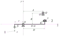
As shown in fig. 2 and 3, the lever ball type universal precision measuring device is composed of a contact
type displacement sensor 1 and a lever ball
type measuring mechanism 2, a rotation center O of the lever ball
type measuring mechanism 2 is used as an origin, a straight line where a horizontal position of a folding rod at the lower side of the lever ball
type measuring mechanism 2 is located is used as an x axis, and a vertical direction is used as a y axis to establish a global coordinate system of the lever ball
type measuring mechanism 2. The basic structural dimensions of the lever ball
type measuring mechanism 2 are C, r, D, E and s respectively. If the measured
part 3 is a non-circular section or the rotation center is not coincident with the geometric center, the lever ball
type measuring mechanism 2 will swing up and down around the rotation center O when the measured
part 3 rotates. The angle between the lever ball
type measuring mechanism 2 and the x-axis is set to be theta, the coordinate of the rotation center O is (0, 0), and the indication value of the
displacement sensor 1 is z. The radius of the circumcircle of the measured
part 3 is R
m The measured cross-section geometric center O' coordinates (A
0 ,B
0 ) The actual rotation center O' of the cross section has the coordinates of (A, B), e and
the measured section eccentric amount (deflection) and the eccentric angle of the measured
part 3 are respectively.
The linear equations of the two folding rods of the contact type displacement sensor 1 and the lever ball type measuring mechanism 2 are respectively as follows:
L 0 :x=-r (1)
L 1 :y=xtan(θ)-C/cos(θ) (2)
L 2 :y=xtan(θ)+E/cos(θ) (3)
substituting formula (1) into formula (2), and removing the initial position-C of the contact displacement sensor 1 at θ=0, the absolute indication value of the contact displacement sensor 1 is obtained as:
z=C-rtan(θ)-C/cos(θ) (4)
according to the plane analysis geometric principle and trigonometric function relation, the geometric center O' (A) 0 ,B 0 ) The coordinate conversion relation with the actual rotation center O' (a, B) is:
in the formula ,
for initial eccentric angle at installation, < >>
To measure the angle through which the section of the part is rotated during the process.
When the lever ball type measuring mechanism 2 is in the horizontal position, the coordinates of the center of sphere of the measuring ball are (D, E), and when the angle between the lever ball type measuring mechanism 2 and the x-axis is θ, the coordinates of the center of sphere of the measuring ball are (x s ,y s ) Is that
No matter the part rotates by any angle, the surface of the part is always contacted with the measuring ball of the lever ball type measuring mechanism 2, and when the section is not eccentric, the estimated value of the lever measuring dip angle theta is
The contour data point vector of the measured
part 3 with the geometric center thereof as the origin of coordinates is (x)
P ,y
P ) Consider them as polar functions of the cross-sectional phase angle gamma, 0<γ<2 pi. Initial phase angle of section posture beta
0 Then when measuring rotation
After the angle, the section coordinates of the part become
Then the distance from any point of the cross section of the part to the center of sphere
At theta m As an initial value, when d Ns When (θ) =0, the θ solution is precisely determined by numerical iteration.
As shown in FIG. 3, the leverage ratio solution model establishment and leverage ratio K in step (2) b The solving process of (2) is as follows:
let K be b For the leverage ratio of the lever ball measuring mechanism 2, the lever ball measuring mechanism can be used for realizing the conversion between the sensor indication z and the eccentric quantity, and the radius R of the circumcircle of the measured section m With a small disturbance ε applied thereto, equations (4) (7) are converted to
z ε (ε)=C-rtan(θ ε )-C/tan(θ ε ) (10)
Bringing (11) into (10), and obtaining the partial derivative of epsilon about (10) and simplifying
As shown in FIG. 4, in step (4), a rotation measurement model without eccentric parts is built and the test signal z is simulated m The acquisition process of the matrix A of the Fourier coefficients of the shape term parameters is as follows:
when the part is not eccentric in the rotation process, all obtained signals come from signal fluctuation caused by the shape of the part, and the signal fluctuation reflects the shape item parameters of the part. No eccentricity e=0, no initial phase angle β of attitude
0 =0, measurement process simulation test signal z
m Along with the rotation angle
The variation relation of (2) is that
Performing Fourier series expansion on the obtained product
wherein ,
A=[a 0 ,a 1 ,b 1 ,a 2 ,b 2 ,...,a k ,b k ,...] T 。
at the same time, the Fourier coefficient matrix of the shape term parameters is converted into A,
as shown in FIG. 5, in the step (6), the test signal component analysis model establishment process of the section with rotation eccentricity and the initial solution estimated value of the section to be tested are carried out
The procedure was as follows:
simulating the test signal z in the presence of a small eccentricity e of the measured section m Essentially a superposition of the shape term and the eccentric term,
fourier expansion is respectively carried out on the shape item and the eccentric item
wherein ,
eccentric term:
wherein ,
The Fourier form of equation (16) is therefore,
by simplifying the equation (19), the attitude angle beta is obtained 0 Is the most significant of (3)The solution formula for the small value and variable c,
the discretized form of formulas (20) (21) is,
wherein ,
for the measurement value of the
contact displacement sensor 1, < >>
For the corner sampling interval, +.>
As the rotation angle vector,
the estimation formulas of the eccentric amount and the eccentric angle of the measured section of the part are as follows,
to this end, an estimated value of the initial solution is obtained
As shown in fig. 5 and 6, the iteration quantity of the cyclic iteration model is the attitude angle β
0 Eccentric amount e and eccentric angle
The convergence evaluation index is the calculation error of the fitting signal and the original signal. The calculation error gradually decreases along with the increase of the iteration times in the iteration solving process, and the accurate solution beta of the measured section is obtained through a certain number of iterations
0 ,e,
FIG. 6 shows the variation of the calculation error with increasing number of iterations, and FIG. 7 (a) (b) (c) shows β, respectively
0 ,e,
A change curve increasing with the number of iterations.
Based on the initial solution estimate obtained in step (6)
By adopting a cyclic iteration mode, for beta
0 ,e,
Performing iterative solution, obtaining an accurate solution after loop convergence, wherein the iterative function is as follows
The discretized form of the iterative function is