CN115053137A - Automatic analyzer - Google Patents
Automatic analyzer Download PDFInfo
- Publication number
- CN115053137A CN115053137A CN202180012741.XA CN202180012741A CN115053137A CN 115053137 A CN115053137 A CN 115053137A CN 202180012741 A CN202180012741 A CN 202180012741A CN 115053137 A CN115053137 A CN 115053137A
- Authority
- CN
- China
- Prior art keywords
- reagent
- dispensing
- unit
- carrying
- dispensing mechanism
- Prior art date
- Legal status (The legal status is an assumption and is not a legal conclusion. Google has not performed a legal analysis and makes no representation as to the accuracy of the status listed.)
- Pending
Links
Images


Classifications
-
- G—PHYSICS
- G01—MEASURING; TESTING
- G01N—INVESTIGATING OR ANALYSING MATERIALS BY DETERMINING THEIR CHEMICAL OR PHYSICAL PROPERTIES
- G01N35/00—Automatic analysis not limited to methods or materials provided for in any single one of groups G01N1/00 - G01N33/00; Handling materials therefor
- G01N35/00584—Control arrangements for automatic analysers
- G01N35/0092—Scheduling
-
- G—PHYSICS
- G01—MEASURING; TESTING
- G01N—INVESTIGATING OR ANALYSING MATERIALS BY DETERMINING THEIR CHEMICAL OR PHYSICAL PROPERTIES
- G01N35/00—Automatic analysis not limited to methods or materials provided for in any single one of groups G01N1/00 - G01N33/00; Handling materials therefor
- G01N35/02—Automatic analysis not limited to methods or materials provided for in any single one of groups G01N1/00 - G01N33/00; Handling materials therefor using a plurality of sample containers moved by a conveyor system past one or more treatment or analysis stations
- G01N35/04—Details of the conveyor system
-
- G—PHYSICS
- G01—MEASURING; TESTING
- G01N—INVESTIGATING OR ANALYSING MATERIALS BY DETERMINING THEIR CHEMICAL OR PHYSICAL PROPERTIES
- G01N35/00—Automatic analysis not limited to methods or materials provided for in any single one of groups G01N1/00 - G01N33/00; Handling materials therefor
- G01N35/00584—Control arrangements for automatic analysers
-
- G—PHYSICS
- G01—MEASURING; TESTING
- G01N—INVESTIGATING OR ANALYSING MATERIALS BY DETERMINING THEIR CHEMICAL OR PHYSICAL PROPERTIES
- G01N35/00—Automatic analysis not limited to methods or materials provided for in any single one of groups G01N1/00 - G01N33/00; Handling materials therefor
- G01N35/02—Automatic analysis not limited to methods or materials provided for in any single one of groups G01N1/00 - G01N33/00; Handling materials therefor using a plurality of sample containers moved by a conveyor system past one or more treatment or analysis stations
- G01N35/025—Automatic analysis not limited to methods or materials provided for in any single one of groups G01N1/00 - G01N33/00; Handling materials therefor using a plurality of sample containers moved by a conveyor system past one or more treatment or analysis stations having a carousel or turntable for reaction cells or cuvettes
-
- G—PHYSICS
- G01—MEASURING; TESTING
- G01N—INVESTIGATING OR ANALYSING MATERIALS BY DETERMINING THEIR CHEMICAL OR PHYSICAL PROPERTIES
- G01N35/00—Automatic analysis not limited to methods or materials provided for in any single one of groups G01N1/00 - G01N33/00; Handling materials therefor
- G01N35/10—Devices for transferring samples or any liquids to, in, or from, the analysis apparatus, e.g. suction devices, injection devices
- G01N35/1002—Reagent dispensers
-
- G—PHYSICS
- G01—MEASURING; TESTING
- G01N—INVESTIGATING OR ANALYSING MATERIALS BY DETERMINING THEIR CHEMICAL OR PHYSICAL PROPERTIES
- G01N35/00—Automatic analysis not limited to methods or materials provided for in any single one of groups G01N1/00 - G01N33/00; Handling materials therefor
- G01N35/00584—Control arrangements for automatic analysers
- G01N35/0092—Scheduling
- G01N2035/0094—Scheduling optimisation; experiment design
-
- G—PHYSICS
- G01—MEASURING; TESTING
- G01N—INVESTIGATING OR ANALYSING MATERIALS BY DETERMINING THEIR CHEMICAL OR PHYSICAL PROPERTIES
- G01N35/00—Automatic analysis not limited to methods or materials provided for in any single one of groups G01N1/00 - G01N33/00; Handling materials therefor
- G01N35/02—Automatic analysis not limited to methods or materials provided for in any single one of groups G01N1/00 - G01N33/00; Handling materials therefor using a plurality of sample containers moved by a conveyor system past one or more treatment or analysis stations
- G01N35/04—Details of the conveyor system
- G01N2035/0439—Rotary sample carriers, i.e. carousels
- G01N2035/0443—Rotary sample carriers, i.e. carousels for reagents
-
- G—PHYSICS
- G01—MEASURING; TESTING
- G01N—INVESTIGATING OR ANALYSING MATERIALS BY DETERMINING THEIR CHEMICAL OR PHYSICAL PROPERTIES
- G01N35/00—Automatic analysis not limited to methods or materials provided for in any single one of groups G01N1/00 - G01N33/00; Handling materials therefor
- G01N35/02—Automatic analysis not limited to methods or materials provided for in any single one of groups G01N1/00 - G01N33/00; Handling materials therefor using a plurality of sample containers moved by a conveyor system past one or more treatment or analysis stations
- G01N35/04—Details of the conveyor system
- G01N2035/0439—Rotary sample carriers, i.e. carousels
- G01N2035/0446—Combinations of the above
-
- G—PHYSICS
- G01—MEASURING; TESTING
- G01N—INVESTIGATING OR ANALYSING MATERIALS BY DETERMINING THEIR CHEMICAL OR PHYSICAL PROPERTIES
- G01N35/00—Automatic analysis not limited to methods or materials provided for in any single one of groups G01N1/00 - G01N33/00; Handling materials therefor
- G01N35/02—Automatic analysis not limited to methods or materials provided for in any single one of groups G01N1/00 - G01N33/00; Handling materials therefor using a plurality of sample containers moved by a conveyor system past one or more treatment or analysis stations
- G01N35/04—Details of the conveyor system
- G01N2035/0439—Rotary sample carriers, i.e. carousels
- G01N2035/0453—Multiple carousels working in parallel
-
- G—PHYSICS
- G01—MEASURING; TESTING
- G01N—INVESTIGATING OR ANALYSING MATERIALS BY DETERMINING THEIR CHEMICAL OR PHYSICAL PROPERTIES
- G01N35/00—Automatic analysis not limited to methods or materials provided for in any single one of groups G01N1/00 - G01N33/00; Handling materials therefor
- G01N35/02—Automatic analysis not limited to methods or materials provided for in any single one of groups G01N1/00 - G01N33/00; Handling materials therefor using a plurality of sample containers moved by a conveyor system past one or more treatment or analysis stations
- G01N35/04—Details of the conveyor system
- G01N2035/046—General conveyor features
- G01N2035/0465—Loading or unloading the conveyor
Abstract
The invention provides an automatic analysis device, wherein a control part (114) plans the actions of a reagent holding mechanism (110) and a reagent conveying mechanism (111) as follows: when a consumable part is transported by a reagent gripping mechanism (110) and a reagent transporting mechanism (111) during analysis of a test object, the operation of a device accessing a storage unit is stopped, and the consumable part is transported even when the operation of the device is stopped, which is inevitably caused later by the stop of the operation of the device. This makes it possible to suppress the occurrence of useless idle cycles that occur when a plurality of consumables are replaced during analysis, as compared with the conventional case.
Description
Technical Field
The present invention relates to an automatic analyzer for performing qualitative/quantitative analysis of a biological sample (hereinafter, referred to as a sample) such as serum or urine.
Background
Documents of the prior art
Patent document
Patent document 1: WO2017/038546
Disclosure of Invention
Problems to be solved by the invention
In automatic analyzers such as biochemical automatic analyzers and immune automatic analyzers, it is necessary to install various consumables for performing analysis, such as reagents corresponding to measurement items of a patient sample, in the analyzers.
The number of consumables to be loaded on the automatic analyzer is reduced by performing analysis. Therefore, when the analysis is continuously performed for a long time, there is a possibility that the analysis is insufficient. In particular, in a large automatic analyzer with a high throughput, the consumption of consumables is also increased.
Therefore, patent document 1 is an example of a technique for carrying a reagent into an automatic analyzer without reducing the throughput of the analyzer during analysis.
In the technique described in patent document 1, when reagent is carried in during analysis, only the movement time of the vertical movement of the gripper mechanism needs to be secured, and therefore only 1 cycle can be used for the movement of carrying the reagent into the reagent tray.
In many cases, 2 or more kinds of reagents are used for items to be analyzed by an automatic analyzer. That is, as in the technique described in patent document 1, if the 1-cycle analysis operation is stopped for reagent loading, the dispensing operation of the second reagent is stopped even after a certain time, and it is known that this time becomes an unnecessary empty cycle, and there is room for improvement.
In addition, in patent document 1, there is no mention of replacement of consumables other than the reagent, and it is clear that there is room for improvement in replenishment of consumables other than the reagent.
An object of the present invention is to solve the above-described problems of the prior art and to provide an automatic analyzer capable of suppressing the occurrence of an unnecessary empty cycle generated when a plurality of consumables are replaced during analysis, as compared with the conventional one.
Means for solving the problems
The present invention includes a plurality of methods for solving the above-described problems, and is an automatic analyzer for analyzing a sample, including: a storage unit for storing consumables used for measuring the test object; a conveying unit that conveys the consumable; and a control unit that creates and operates an operation plan of each device in the automatic analyzer including the transport unit, wherein the control unit plans the operation of the transport unit as follows: when the consumable part is transported by the transport part in the analysis of the object, the operation of the device accessing the storage part is stopped, and the consumable part is transported also at the time of the operation stop of the device which is inevitably generated later due to the stop.
Effects of the invention
According to the present invention, it is possible to suppress the occurrence of useless empty cycles that occur when a plurality of consumables are replaced during analysis, as compared with the conventional art. Problems, configurations, and effects other than those described above will be apparent from the following description of the embodiments.
Drawings
FIG. 1 is a plan view of an automatic analyzer according to embodiment 1 of the present invention.
Fig. 2 is a timing chart when reagent containers are carried in when the reagent containers can be carried in 1 cycle in the automatic analyzer of example 1.
Fig. 3 is a timing chart at the time of carrying in a reagent container in a case where the reagent container can be carried in 2 cycles in the automatic analyzer of example 1.
FIG. 4 is a diagram showing an analysis plan of an automatic analyzer according to embodiment 1.
Fig. 5 is a diagram showing a scheduling method of a reagent dispensing mechanism in the automatic analyzer according to embodiment 1.
Fig. 6 is a diagram showing a scheduling method of a reagent dispensing mechanism in the automatic analyzer according to embodiment 1.
Fig. 7 is a diagram showing a scheduling method of a reagent dispensing mechanism in an automatic analyzer according to embodiment 1.
FIG. 8 is a flowchart of the mechanism reservation in the case where 2 reagent containers are loaded into the automatic analyzer of example 1.
FIG. 9 is a flowchart of the mechanism reservation in the case where an arbitrary number of reagent containers are loaded into the automatic analyzer of example 1.
FIG. 10 is a flowchart of the mechanism reservation in the case where an arbitrary number of reagent containers are loaded into the automatic analyzer according to example 2 of the present invention.
FIG. 11 is a flowchart of the mechanism reservation in the case where an arbitrary number of reagent containers are loaded into the automatic analyzer according to embodiment 3 of the present invention.
Fig. 12 is a diagram showing a scheduling method of a reagent dispensing mechanism in an automatic analyzer according to embodiment 3.
Fig. 13 is a diagram showing a scheduling method of a reagent dispensing mechanism in an automatic analyzer according to embodiment 4 of the present invention.
FIG. 14 is a timing chart in the case where reagent containers are carried in and out in a set as exemplified in example 5 of the present invention.
FIG. 15 is a plan view of an automatic analyzer according to embodiment 6 of the present invention.
Detailed Description
Hereinafter, an embodiment of the automatic analyzer according to the present invention will be described with reference to the drawings.
< example 1>
First, the overall configuration of the automatic analyzer will be described with reference to fig. 1. Fig. 1 is a plan view of an automatic analyzer to which the present invention is applied.
An automatic analyzer 101 shown in fig. 1 is a device for dispensing a sample and a reagent into each of a plurality of reaction vessels 103, reacting the samples, and measuring a liquid after the reaction, and includes a reaction disk 102, a reagent disk 104, a sample transfer mechanism 117, a first reagent dispensing mechanism 108, a second reagent dispensing mechanism 109, a sample dispensing mechanism 112, an automatic loading mechanism, a light source 115a, a spectrophotometer 115b, a cleaning mechanism (not shown), an agitation mechanism (not shown), a cleaning tank (not shown), and a control unit 114.
In the reaction disk 102, the reaction vessels 103 are arranged on the circumference, and are rotated at a constant angle all the time during analysis, and the reaction vessels 103 are moved to various positions such as a sample dispensing position, a reagent dispensing position, and a photometric position by the rotation.
A sample transport mechanism 117 for moving a rack 118 on which a sample container 119 is placed is provided near the reaction disk 102. Instead of the object transport mechanism 117, another method such as a method in which the operator sets the object by hand may be used.
A sample dispensing mechanism 112 that can rotate and move up and down is provided between the reaction disk 102 and the sample transport mechanism 117. The sample dispensing mechanism 112 moves around a rotation axis while drawing an arc, and dispenses a sample from the sample container 119 into the reaction container 103.
The reagent disk 104 is a storage container capable of placing a plurality of reagent containers 120 containing therein reagents for analysis on the circumference, and rotates to move an arbitrary reagent to a reagent aspirating position. The reagent disk 104 is kept cooled and covered by a cover body having a suction port 104a to which the first reagent dispensing mechanism 108 and the second reagent dispensing mechanism 109 access when dispensing a reagent into the reaction container 103, and a loading port 105 for loading the reagent container 120 into the reagent disk 104.
A first reagent dispensing mechanism 108 and a second reagent dispensing mechanism 109 that are rotatable and vertically movable are provided between the reaction disk 102 and the reagent disk 104. The first reagent dispensing mechanism 108 and the second reagent dispensing mechanism 109 move around a rotation axis while drawing an arc, access the inside of the reagent disk 104 from the suction port 104a, and dispense a reagent from the reagent container 120 to the reaction container 103. The first reagent dispensing mechanism 108 and the second reagent dispensing mechanism 109 are configured to be able to access the reagent disk 104 simultaneously.
A cleaning mechanism, a light source 115a, a spectrophotometer 115b, and a stirring mechanism are also disposed around the reaction disk 102. In addition, cleaning tanks are provided in the operating ranges of the first reagent dispensing mechanism 108, the second reagent dispensing mechanism 109, the sample dispensing mechanism 112, and the stirring mechanism, respectively.
The control unit 114 is constituted by a computer or the like connected to the above-described respective mechanisms, and performs control for creating and operating an operation plan of each device in the automatic analyzer 101, and performs arithmetic processing for obtaining a predetermined component concentration in a liquid sample such as blood or urine. The control unit 114 of the present embodiment has a display unit 114a for displaying the state of the automatic analyzer 101.
Further, the control section 114 of the present embodiment performs the following control: in order to suspend the scheduling of the dispensing operation of the first reagent dispensing mechanism 108 and the second reagent dispensing mechanism 109 in order to carry 1 reagent into or out of the reagent disk 104 during analysis, another reagent is carried into or out of the reagent disk 104 at the time of the operation suspension of the second reagent dispensing mechanism 109 which is inevitably generated later due to the suspension of the scheduling of the operation of the first reagent dispensing mechanism 108. The details of this control are described later.
Further, the control unit 114 of the present embodiment executes the following control: the display unit 114a displays the time required until the completion of the conveyance of all the consumables requested by the operator.
The automatic loading mechanism is disposed above the reagent disk 104, and includes a reagent conveying mechanism 111, a reagent gripping mechanism 110, and the like.
The inlet 105 is a cover for preventing cold air from escaping from the cooled reagent disk 104, and is normally closed. The reagent holding mechanism 110 is operated so that the input port 105 is opened when accessing the reagent disk 104, and the reagent container 120 can be loaded into and unloaded from the reagent disk 104.
The reagent tray 107 is a portion for installing the reagent containers 120 when the operator carries the reagent containers 120 into the reagent disk 104 of the automatic analyzer 101, or a portion on which the reagent containers 120 carried out from the reagent disk 104 are placed, and in fig. 1, is configured such that a plurality of reagent containers 120 can be installed in a plurality of straight lines. The reagent tray 107 is not limited to a tray shape, and its shape is not particularly limited as long as it is a shape capable of placing the reagent container 120, such as a disk shape or a shelf shape with a door.
The reagent transfer mechanism 111 is provided above the reagent disk 104, and moves in the vertical direction in fig. 1. The reagent transfer mechanism 111 is provided with a reagent gripping mechanism 110, and in fig. 1, the reagent gripping mechanism 110 moves in the left-right direction of the drawing along the vertical direction of the drawing and the longitudinal direction of the reagent transfer mechanism 111. The reagent container 120 is automatically transported to either the reagent disk 104 or the reagent tray 107 by the reagent grasping mechanism 110 and the reagent transporting mechanism 111.
The above is the configuration of the automatic analyzer 101 of the present embodiment.
In this embodiment, a reagent is exemplified as a consumable. In this case, the storage unit for storing consumables used for measuring the test object is configured by the reagent disk 104 and the reagent tray 107, and the device for accessing the reagent disk 104 corresponds to the first reagent dispensing mechanism 108 for dispensing the first reagent (hereinafter referred to as R1) of the reagents and the second reagent dispensing mechanism 109 for dispensing the second reagent (hereinafter referred to as R2). The first reagent dispensing mechanism 108 corresponds to a first dispensing unit, and the second reagent dispensing mechanism 109 corresponds to a second dispensing unit.
It should be noted that, as for the configuration of the automatic analyzer, a case of a 1-system automatic analyzer having only 1 reagent disk 104 as shown in fig. 1 is exemplified, but in the present invention, any mechanism can be applied to a 2-system, or even 3-system or more automatic analyzer having 2 reagent disks and a dedicated dispensing mechanism for each reagent disk, as long as the other reagent dispensing mechanism does not interfere with one reagent disk when the reagent container 120 is loaded into the other reagent disk, regardless of whether the reagent dispensing mechanism and the automatic loading mechanism do not interfere with each other.
The analysis device may be an analysis device that performs analysis of other analysis items, such as an immunoassay device that performs analysis of an immunoassay analysis item, instead of the analysis of a biochemical analysis item. The biochemical analyzer is not limited to the embodiment shown in fig. 1, and various mechanisms may be added or deleted as appropriate, an analyzer for measuring other analysis items such as an electrolyte may be separately mounted, or the number of the mechanisms shown in fig. 1 may be changed as appropriate.
The automatic analyzer is not limited to the configuration of a single analysis module as shown in fig. 1, and may be configured by connecting 2 or more analysis modules capable of measuring various identical or different analysis items and a handling device for a pretreatment module for performing pretreatment.
The analysis process of the test object by the automatic analyzer 101 as described above is generally performed in the following order.
First, the test object in the test object container 119 placed on the rack 118 conveyed to the test object suction position 113 by the test object conveying mechanism 117 is dispensed to the reaction container 103 on the reaction disk 102 by the test object dispensing mechanism 112.
When the reaction disk 102 is stopped after a predetermined time period after the test object is discharged into the reaction vessel 103, the discharge position of the reaction vessel is aligned with the discharge position of the first reagent dispensing mechanism 108. In this timing, a first reagent used for analysis is dispensed from a reagent container 120 on a reagent disk 104 to a reaction container 103 to which a test substance has been previously dispensed, by a first reagent dispensing mechanism 108. Next, the mixed liquid of the sample and the reagent in the reaction container 103 is stirred by the stirring mechanism.
After the fixed time, R2 is dispensed from the reagent container 120 on the reagent disk 104 to the reaction container 103 into which the first reagent has been previously dispensed by the second reagent dispensing mechanism 109 as necessary.
In the cycle between the series of dispensing operations, the light generated from the light source 115a is transmitted through the reaction vessel 103 containing the mixed solution, and photometry is performed for each cycle, and the photometry measures the light intensity of the transmitted light by the spectrophotometer 115 b. Here, in the present invention, 1 cycle is set as an interval between photometry and photometry.
Then, the light intensity measured by the spectrophotometer 115b is transmitted to the control unit 114 via the a/D converter and the interface. Then, the control unit 114 calculates the concentration of a predetermined component in a liquid sample such as blood or urine, and the result is displayed on the display unit 114a or the like or recorded in a recording device.
When all the reactions are completed, the reaction solution in the reaction container 103 is removed by the cleaning mechanism and cleaned. After the cleaning is completed, the reaction vessel 103 is used again for analysis.
The procedure of carrying the reagent container 120 in the analysis of this apparatus will be described below.
As described above, the reagent disk 104 has the inlet port 105 and is closed by the shutter in a flat state. The gate may be a slide type gate, a single-opening type gate, a double-opening type gate, or the like as long as the gate is openable and closable.
Upon receiving the reagent loading request, the automatic loading mechanism grips the reagent container 120 placed on the reagent tray 107 and moves the reagent container to the standby position 106. When the reagent disk 104 and the reagent dispensing mechanism are stopped, the shutter of the input port 105 is opened, and the automatic loading mechanism stores the reagent container 120 in the reagent disk 104. After that, when the automatic loading mechanism returns to the standby position, the first reagent dispensing mechanism 108 and the second reagent dispensing mechanism 109 start operating again.
In the present embodiment, the automatic loading mechanism is disposed so as not to interfere with the second reagent dispensing mechanism 109 at all. While the automatic loading mechanism is moving from the reagent tray 107 to the standby position 106, the automatic loading mechanism is arranged so as not to interfere with the first reagent dispensing mechanism 108.
When the automatic loading mechanism is configured not to interfere with the first reagent dispensing mechanism 108 and the second reagent dispensing mechanism 109, the present invention has a high effect of suppressing a decrease in flux, but does not necessarily need to be configured not to interfere with each other. In the case of disturbance, in addition to the time required for carrying in, the first reagent dispensing mechanism 108 and the second reagent dispensing mechanism 109 can be stopped during the period in which both mechanisms are disturbed.
In the present embodiment, a timing chart when the reagent vessel 120 is loaded into the reagent disk 104 during analysis will be described with reference to fig. 2 and 3. Fig. 2 is a timing chart in the case where the reagent vessel can be carried in 1 cycle in the automatic analyzer according to example 1, and fig. 3 is a timing chart in the case where the reagent vessel can be carried in 2 cycles.
In the present embodiment, the time taken for the first reagent dispensing mechanism 108 and the second reagent dispensing mechanism 109 to aspirate and discharge the reagent is 1 cycle. Here, the start position in fig. 2 refers to a position at which the apparatus is stopped when it is in a standby state where no analysis is performed.
The following describes the operation until the automatic loading mechanism carries the reagent container 120 from the standby position 106 to the reagent tray 104 and returns to the position of the reagent tray 107 again when the cycle related to the carrying-in is 1 cycle.
The first cycle is a normal analysis operation, and the first reagent dispensing mechanism 108 sucks the reagent stored in the reagent disk 104, moves to a position where the reagent is discharged, discharges the reagent into the reaction vessel 103, and returns to the starting point. The second reagent dispensing mechanism 109 discharges the reagent into the reaction container 103, moves the next reagent to the suction position of the reagent disk 104, and suctions the reagent.
At this time, since the reagent disk 104 is accessed to aspirate 2 types of reagents, 2 rotations are performed in 1 cycle so that the position of the reagent aspirated by the first reagent dispensing mechanism 108 is aligned with the aspiration port 104a in the first half of the cycle and the position of the reagent aspirated by the second reagent dispensing mechanism 109 is aligned with the aspiration port 104a in the second half of the cycle. The automatic loading mechanism stops at the standby position 106 while holding the loaded reagent container 120.
The second cycle is a reagent loading operation, and the first reagent dispensing mechanism 108 and the second reagent dispensing mechanism 109 do not access the reagent disk 104. Since the second reagent dispensing mechanism 109 does not interfere with the automatic loading mechanism, it is possible to perform the operation of discharging the reagent to the reaction container 103 having been aspirated in the first cycle before.
The reagent disk 104 is rotated so that the position where the carried-in reagent container 120 is set is aligned with the inlet port 105, and the shutter is opened after the rotation is stopped. During this operation, the reagent transfer mechanism 111 moves to the upper portion of the inlet 105. When the shutter is fully opened, the reagent holding mechanism 110 is lowered to set the reagent container 120 on the reagent disk 104. When the reagent gripping mechanism 110 returns to the position before the lowering, the reagent transfer mechanism 111 moves to the standby position 106. During this time, the gate is closed.
The analysis is started again in the third cycle. The first reagent dispensing mechanism 108 moves to a reagent aspirating position on the reagent disk 104 for aspirating a reagent. At the same time, the reagent disk 104 rotates, and the aspirated reagent moves to the aspiration position. When the reagent suction by the first reagent dispensing mechanism 108 is completed, the reagent disk 104 is rotated again, and the reagent dispensed by the second reagent dispensing mechanism 109 is moved to the suction position. The second reagent dispensing mechanism 109 moves to the aspirating position in the latter half of the cycle, and performs a reagent aspirating operation. The reagent conveying mechanism 111 moves from the standby position to the home position.
Here, the conditions as the premise are supplemented. In the case where the automatic loading mechanism interferes with the second reagent dispensing mechanism 109 while moving from the standby position 106 to the input port 105, the automatic loading mechanism deals with scheduling such that the second reagent dispensing mechanism 109 returns to the starting point without performing the pipetting operation in the second half of the first cycle.
When the automatic loading mechanism is configured to be unable to move to the standby position before the second cycle is completed, the automatic loading mechanism is handled by scheduling so as not to perform the operation of the first reagent dispensing mechanism 108 in the first half of the third cycle.
That is, the present invention can be applied regardless of the presence or absence of interference between the first reagent dispensing mechanism 108, the second reagent dispensing mechanism 109, and the automatic loading mechanism.
When the time taken to replace the reagent container 120 is 2 cycles or more, the reagent container can be loaded by the same method. Fig. 3 shows a timing chart in the case of carrying in 2 cycles.
Fig. 3 is a scheme in which the time taken for the automatic loading mechanism to carry the reagent container 120 into the reagent disk 104 is long, assuming that the operation of the automatic loading mechanism is slow compared to the operation of the dispensing mechanism.
In addition to the embodiment shown in fig. 3, the present invention is also applicable to a case where the standby position 106 is formed only at a position away from the reagent disk 104 due to interference with the first reagent dispensing mechanism 108, and the automatic loading mechanism takes time to transport from the standby position 106 to the input port 105.
Next, a method of scheduling the carrying in and carrying out of the reagent container 120 in the automatic analyzer of the present invention will be described in detail below with reference to fig. 4 and subsequent drawings. Fig. 4 is a diagram showing an analysis plan.
The automatic analyzer 101 of embodiment 1 is a biochemical automatic analyzer that periodically performs photometry, and as shown in fig. 4, when the control unit 114 determines photometry timing and reagent dispensing timing, and dispenses a sample, reagent dispensing must be performed at the set timing.
That is, when the first reagent dispensing mechanism 108 and the second reagent dispensing mechanism 109 are to be stopped in the cycle of the timing 401 shown in fig. 4, the sample dispensing performed at the timing 402 needs to be interrupted in advance.
In this way, it is desirable to schedule a sample dispensing plan after checking that a required reagent dispensing is possible when the sample dispensing is performed with reference to the operating state of the reagent dispensing mechanism. By making the operation plan by the scheduling method, the subsequent dispensing of the test object can be planned so as not to overlap the carrying-in operation.
In addition, there are various analysis methods in the automatic analyzer depending on the analysis items and manufacturers, and the above schedule is only an example, and is not particularly limited as long as the automatic analyzer performs analysis using 2 or more kinds of reagents.
Based on the operations of the various mechanisms, the control unit 114 of the present embodiment stops the operation of the device accessing the storage unit when the reagent is transported by the reagent gripping mechanism 110 and the reagent transporting mechanism 111 during the analysis of the test object. At the same time, the operations of the reagent gripping mechanism 110 and the reagent conveying mechanism 111 are planned so that the reagent is conveyed even when the operation of the apparatus is stopped, which is inevitably caused later due to the stoppage. The following describes details of the planning method with reference to fig. 5 to 7. Fig. 5 to 7 are diagrams illustrating a scheduling method of the reagent dispensing mechanism.
Upon receiving the transfer request of the reagent container 120, the control unit 114 interrupts the subsequent cycle 501 of sample dispensing, as shown in fig. 5. Since the cycle 502A, which is the timing of the sample dispensing R1, does not require the dispensing of R1 due to the interruption of the sample dispensing, the operation stop reservation of the first reagent dispensing mechanism 108 is performed. Similarly, for the cycle 502B, which is the timing of the sample dispensing R2, an operation reservation for stopping the second reagent dispensing mechanism 109 is performed.
In order to reserve the stopping operation (i.e., the loading operation of the reagent container 120) of the cycle 502B, it is necessary to stop the rotation operation of the reagent disk 104 at the same time when the cycle 502B is performed. Therefore, the dispensing operation of the first reagent dispensing mechanism 108 also has to be stopped at the same timing as the cycle 502B. Therefore, as shown in fig. 6, the control unit 114 performs an operation reservation for stopping the first reagent dispensing mechanism 108 for the cycle 503.
Since the operation of the first reagent dispensing mechanism 108 in this cycle 503 is stopped, as shown in fig. 7, the sample dispensing corresponding to the cycle 503 is not necessary, and therefore, the operation of the sample dispensing mechanism 112 in the cycle 504 is also scheduled to be stopped. The control unit 114 performs scheduling of sample dispensing so as to restart the sample dispensing schedule from the next cycle, without performing sample dispensing in the cycles of the cycles 501 and 504.
Further, in a cycle 504 of sample dispensing that is interrupted to stop the first reagent dispensing mechanism 108 in the cycle 503, as shown in fig. 7, a cycle 505 of stopping the second reagent dispensing mechanism 109 inevitably occurs.
When the second reagent container 120 is loaded in this cycle 505, the operation reservation of the automatic loading mechanism is performed, and the operation reservation of the second reagent container 120 is completed.
If there is a reagent container 120 to be carried in, an operation reservation for stopping the first reagent dispensing mechanism 108 is further made for the cycle 506 based on the reservation for the stop operation for the cycle 505. Similarly, the timing of stopping the operations of the sample dispensing mechanism 112 and the second reagent dispensing mechanism 109 inevitably occurs later due to the stop operation reservation of the cycle 506. When the timing is inevitably generated, the loading operation of the third and subsequent reagent containers 120 can be scheduled.
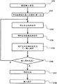
The actual carrying-in operation will be described with reference to fig. 8. Fig. 8 is a flowchart of the mechanism reservation when 2 reagent containers are loaded.
When the carry-in request is received, the operations of the first reagent dispensing mechanism 108 and the second reagent dispensing mechanism 109 are stopped during the timing of the reserved cycles 502A and 502B (step S601).
Therefore, the first reagent container 120 is carried in at this timing (step S602).
As described above, the first reagent dispensing mechanism 108 is stopped in the cycle 503 by the carrying-in operation in the previous step S602 (step S603). Since the first reagent dispensing mechanism 108 is stopped in step S603 and the second reagent dispensing mechanism 109 is also stopped in the cycle 505, the second reagent container 120 is carried in the cycle 505 (step S604), and the carrying in is completed.
Next, the flow of reagent registration will be described with reference to fig. 9. Fig. 9 is a flowchart of the mechanism reservation in the case where an arbitrary number of reagent containers are loaded.
Upon receiving the loading request (step S701), the control unit 114 searches for a first loadable cycle based on the steps of fig. 8 (step S702), reserves the stop operations of the first reagent dispensing mechanism 108 and the second reagent dispensing mechanism 109 in the loadable cycle (step S703), and also performs the operation reservation of the automatic loading mechanism (step S704).
Then, the control unit 114 sets an empty cycle of the second reagent dispensing mechanism 109, which is generated by stopping the operation of the first reagent dispensing mechanism 108 in step S703, as a next loadable cycle (step S705).
Next, the control unit 114 determines whether or not the loading reservation of all reagents is completed (step S706). If it is determined that the reservation has been completed, the process proceeds to step S707, and if it is determined that the reservation has not been completed, the process returns to step S703.
Next, the control unit 114 completes the reservation of the automatic loading mechanism, the reagent disk 104, and each dispensing mechanism (step S707), waits for the elapse of time, and executes a carry-in operation at the timing of the reservation (step S708).
Here, the carrying-in operation of the present embodiment takes up to 10 minutes when 5 reagent containers 120 are carried into the reagent disk 104. If the analysis operation is resumed between the carry-in and the carry-in, the operator may not be able to determine whether the carry-in operation is normally performed, and may feel uneasy as to whether the instruction is accurately performed.
Therefore, it is preferable that the display unit 114a clearly indicates when the loading is finished. For example, the remaining time may be displayed in a portion of the display unit 114a that displays the state of the apparatus, or if there is a reagent management screen, the reagent may be individually displayed to be carried in a few minutes later. The display of the time and the like until the completion of the loading is not limited to the display unit 114a that displays the screen for operating the entire apparatus, and various display devices such as a small-sized display provided in the apparatus and an LED that notifies the operator of the status of the display device by the lighting state may be used.
As described above, it is assumed that the reagent disk 104 has more than the number of empty positions of the reagent containers 120 to be loaded in advance, but it is needless to say that there may be no empty positions.
In such a case, when an empty reagent container 120 is present in the reagent disk 104 and a reagent container 120 that is not supposed to be used in the current period is present, it is preferable to carry out the reagent disk before a carry-in request for a new reagent container 120 is input.
Therefore, when there is an empty reagent container 120 during analysis, the control unit 114 preferably creates a carrying-out plan for taking out the reagent. The method of creating a carrying-out plan for carrying out the reagent containers 120 from the reagent disk 104 and the carrying-out step are different from each other in that the operation of the automatic loading mechanism is opposite to the carrying-in operation, and the reagent containers 120 to be carried out are set on the reagent tray 107. The same applies to the following embodiments. Note that the same reagent tray 107 is used for carrying in and carrying out, but the tray may be separated for carrying in and carrying out.
Next, the effects of the present embodiment will be described.
The automatic analyzer 101 according to embodiment 1 of the present invention includes: a storage unit for storing consumables used for measuring a test object; a reagent gripping mechanism 110 and a reagent conveying mechanism 111 for conveying consumables; and a control unit 114 that creates and operates an operation plan for each device in the automatic analyzer 101 including the reagent holding mechanism 110 and the reagent transfer mechanism 111, wherein the control unit 114 plans the operations of the reagent holding mechanism 110 and the reagent transfer mechanism 111 as follows: when a consumable part is transported by the reagent gripping mechanism 110 and the reagent transporting mechanism 111 during analysis of a sample, the operation of the device accessing the storage unit is stopped, and the consumable part is transported even when the operation of the device is stopped, which inevitably occurs later due to the stop.
In the case where the consumable part is a reagent, in the related art, in order to carry in 1 reagent container 120, it is necessary to interrupt the sample dispensing for 2 cycles in total among the sample dispensing interruption caused by stopping the first reagent dispensing mechanism 108 and the sample dispensing interruption caused by stopping the second reagent dispensing mechanism 109. That is, the dispensing of 4 cycles needs to be interrupted for 2 reagent containers 120, and the dispensing of 2n cycles needs to be interrupted for n reagent containers 120. Here, n is a natural number of 1 or more, and the upper limit is the number of reagent containers 120 that can be stored in the reagent disk 104.
In contrast, according to the present invention, the interrupt cycle of the sample dispensing required for carrying in n reagent containers 120 is (n +1) cycles, and in the present embodiment, the sample dispensing interrupted by carrying in 2 reagent containers 120 can be suppressed to 3 cycles. That is, as compared with the conventional art, the same number of reagent containers 120 can be loaded into the apparatus n-1 cycles less. Therefore, the occurrence of wasteful idle cycles that occur when a plurality of consumables are replaced during analysis can be suppressed as compared with the conventional, and the throughput of analysis can be suppressed from decreasing as compared with the conventional.
According to the control of the control unit 114, when a plurality of consumables are requested to be loaded at one time, it takes time until the last reagent is loaded to the end, compared to the conventional case. Further, since the measurement operation is performed as usual in addition to the short time for carrying in, it may be difficult to determine whether the replacement is completed or in the middle by the observation device.
However, since the display unit 114a that displays the state of the automatic analyzer 101 is further provided, and the control unit 114 displays the time required until the completion of the conveyance of all the consumables requested by the operator on the display unit 114a, the replacement work instructed becomes clear in accordance with the instruction, so that the operator can concentrate on other works with ease and can plan the next work based on the prediction of the completion. Therefore, the analysis work of the operator can be made more efficient.
Further, the storage unit includes a reagent disk 104 for storing a reagent used for analysis, and a reagent tray 107 on which a reagent carried into the reagent disk 104 or a reagent carried out from the reagent disk 104 is placed, and the reagent gripping mechanism 110 and the reagent carrying mechanism 111 carry the reagent to either the reagent disk 104 or the reagent tray 107, and the device for accessing the reagent disk 104 includes a first reagent dispensing mechanism 108 for dispensing R1 among reagents, and a second reagent dispensing mechanism 109 for dispensing R2 among the reagents. As described above, by applying the control of the present invention to the automatic loading mechanism that automatically carries in and out the reagent container 120 in place of the operator, the load on the operator can be reduced, and the effect of suppressing the decrease in the throughput of the analysis can be obtained significantly.
The first reagent dispensing mechanism 108 and the second reagent dispensing mechanism 109 can simultaneously access the reagent disk 104, and the control unit 114 suspends the scheduling of the dispensing operation of the first reagent dispensing mechanism 108 and the second reagent dispensing mechanism 109 in order to carry 1 reagent into or out of the reagent disk 104 during the analysis, and carries other reagents into or out of the reagent disk 104 at the time of the operation suspension of the second reagent dispensing mechanism 109 which is inevitably generated later due to the suspension of the operation scheduling of the first reagent dispensing mechanism 108. By executing the transport control described above for the reagent container 120 that is the largest in-and-out of which the consumable supplies are carried in and out, the effect of suppressing a decrease in the analysis throughput due to the interruption of the analysis can be obtained to a large extent.
< example 2>
An automatic analyzer according to embodiment 2 of the present invention will be described with reference to fig. 10. Fig. 10 is a flowchart of the mechanism reservation in the case where an arbitrary number of reagent containers are loaded into the automatic analyzer of example 2.
In the present embodiment, the same components as those in embodiment 1 are denoted by the same reference numerals, and description thereof is omitted. The same applies to the following examples.
The automatic analyzer of the present embodiment is configured to be capable of switching between transport control for carrying in and out the reagent containers 120 during analysis described in embodiment 1 and transport control for interrupting analysis at that point of time and continuously carrying in and out all reagents when a carry-in instruction is received from an operator, and the operator can instruct the apparatus which transport control should be executed.
The transport control for interrupting the analysis at this point and transporting the plurality of reagent containers 120 during the analysis has an advantage that the time from the start of the transport to the end thereof is short, although the analysis throughput is reduced as compared with the transport control using the stop timing that inevitably occurs as in example 1.
In actual operation, there are cases where it is desired to prioritize the completion of the transfer over the throughput, such as cases where the remaining amount of reagent in the apparatus is reduced and the transfer is desired to be performed immediately.
Therefore, it is preferable that the control unit 114 separately uses the plan for carrying in or carrying out the reagent by the time of the stoppage which inevitably occurs as described in embodiment 1 and the plan for continuing the carrying in or carrying out of all the reagents instructed by the operator.
It is preferable that the plan for carrying in or out the reagent at the time of stoppage which is inevitably generated and the plan for continuing carrying in or out all the reagents instructed by the operator can be selected and used.
As an example of the selection method, a method of switching by a dedicated selection button provided in the apparatus, a selection screen displayed on the display portion 114a, or a toggle switch may be mentioned. If the button is selected, a conveyance method using a stop timing which is inevitably generated if the button is pressed for a short time or a conveyance method using a continuous conveyance of all reagents instructed by the operator if the button is pressed for a long time can be implemented. In addition, a method of making a selection by a pressing method of a button is described, but a selection may be made by pressing a button several times. Further, 2 kinds of buttons may be prepared and selected according to the pressed button.
In addition, although the method capable of selecting 2 reagent loading methods is described in the present embodiment, in the case where there are 3 or more reagent loading methods, it is possible to cope with this by preparing a method of pressing a button for each method.
The switching of the transport control may be automatically performed according to the necessity of the reagent container 120 instructed to be carried in by the control unit 114.
Next, the flow of reagent registration in this embodiment will be described with reference to fig. 10.
As shown in fig. 10, first, when receiving a carry-in request (step S801), the control unit 114 determines which of transport control using a reagent at a time of stopping that inevitably occurs and transport control for continuing carry-in and carry-out of all reagents instructed by an operator should be used (step S801). When it is determined that the continuous transport control should be executed, the process proceeds to step S802, and the control unit 114 interrupts the sample dispensing of the next cycle, and performs the automatic loading mechanism operation reservation in accordance with the reserved reagent amount in a lump (step S802).
Next, the control unit 114 performs the stop mechanism reservation of the second reagent dispensing mechanism 109 in the cycle in which the second reagent dispensing mechanism 109 is disabled by the interference with the automatic loading mechanism (step S803), performs the stop mechanism reservation of the first reagent dispensing mechanism 108 in the cycle in which the first reagent dispensing mechanism 108 is disabled by the interference with the automatic loading mechanism (step S804), and advances the process to step S810.
On the other hand, if it is determined in step S801 that each of the 1 conveyance controls should be executed as in embodiment 1, the process proceeds to step S805. Steps S805 to S811 are substantially the same as steps S702 to S708 shown in fig. 9, and therefore, detailed description thereof is omitted.
The other configurations and operations are substantially the same as those of the automatic analyzer of embodiment 1, and detailed description thereof is omitted.
The automatic analyzer according to embodiment 2 of the present invention can also obtain substantially the same effects as those of the automatic analyzer according to embodiment 1.
Further, the control unit 114 can appropriately switch the transport control between a case where it is desired to suppress a decrease in the throughput and a case where it takes no time for the transport by separately using a reagent carrying-in/out plan using a necessary stop timing and a plan for continuing carrying-in/out of all reagents instructed by the operator, and can thus cope with various situations at random.
Further, since it is possible to select which of a reagent carrying-in/out plan at the time of stopping and a plan for continuing carrying-in/out of all reagents instructed by the operator is used, it is possible to cope with various situations with random strain of the operator's hand, and it is possible to more efficiently perform analysis work.
< example 3>
An automatic analyzer according to embodiment 3 of the present invention will be described with reference to fig. 11 and 12. Fig. 11 is a flowchart of the mechanism reservation in the case where an arbitrary number of reagent containers are loaded into the automatic analyzer of example 3. Fig. 12 is a diagram illustrating a scheduling method of a reagent dispensing mechanism. Fig. 12 is an example, and changes according to the operating conditions of the apparatus.
In example 1, the control of the cycle of carrying in the reagent container 120 is intentionally performed. In this case, since it takes about 5 minutes at most from the time of dispensing the test object to the dispensing R2, it takes about 10 minutes at most for 5 reagent containers 120 from the time when the operator makes a loading request to the time when the reagent containers 120 are loaded.
Therefore, the reagent containers 120 can be carried in at the timing when continuous empty cycles of not less than the number of cycles necessary for carrying in the reagent containers 120 by the second reagent dispensing mechanism 109 occur within about 5 minutes of the planned mechanism operation, thereby reducing the time taken for carrying in the reagent containers 120.
In an apparatus used in an actual clinical site, all reagent dispensing mechanisms are rarely operated at an operation rate of 100%. Therefore, the second reagent dispensing mechanism 109 may naturally generate an idle cycle.
Since the time taken from the time when the sample is dispensed to the time when the first reagent dispensing mechanism 108 operates is several seconds, if a cycle in which the reagent container 120 can be carried into the second reagent dispensing mechanism 109 occurs naturally, the sample dispensing can be interrupted and the carrying-in operation can be performed so that the first reagent dispensing mechanism 108 is stopped at the same timing.
Therefore, the control unit 114 of the automatic analyzer according to the present embodiment determines whether or not there is a free time equal to or longer than a time required for carrying in or out a reagent in a reagent dispensing plan when a request is made to carry in or out a reagent to the reagent disk 104, carries in or out a reagent by the free time when there is a free time, and stops the dispensing operation of the first reagent dispensing mechanism 108 and the second reagent dispensing mechanism 109 and carries in or out a reagent when there is no free time.
Next, the flow of reagent registration in this embodiment will be described with reference to fig. 11 and 12.
As shown in fig. 11, when the control unit 114 first receives a carry-in request (step S900), it searches whether or not there is an empty cycle 1001 in which all the requested reagent containers 120 can be continuously carried in until the cycle 1002 of the operation of the second reagent dispensing mechanism 109 planned at the present time shown in fig. 12 (step S901). If it is determined that there is a continuous empty cycle 1001, the process proceeds to step S910, and a transport plan for continuously carrying in all the reagents described in embodiment 2 is created and executed (steps S910 to S915).
On the other hand, if it is determined that there is no empty loop 1001, the process proceeds to step S902. Next, the control unit 114 determines whether there are the natural air-conditioning cycles of the number of conveyance requests that originally exist for one shot without using the method described in the first embodiment and the like (step S902). If it is determined that there are empty cycles in which the requested number of all the reagent containers 120 can be transported, the process proceeds to step S904, and a plan for transporting all the reagents is created and executed (steps S904 to S915).
On the other hand, if it is determined that there are a number of empty cycles that can be transported, which is equal to the number of all the reagent containers 120, the process proceeds to step S903, and a loading plan for loading the remaining reagent containers 120 as in example 1 is created and executed using the empty cycle that occurs when reagent containers 120 are loaded in the naturally occurring empty cycle (steps S903 to S915).
Steps S904 to S907 are substantially the same as steps S703 to S706 shown in fig. 9, and steps S910 to S915 are substantially the same as steps S703 to S708 shown in fig. 9, and therefore, detailed description thereof is omitted.
The other configurations and operations are substantially the same as those of the automatic analyzer of embodiment 1, and detailed description thereof is omitted.
The automatic analyzer according to embodiment 3 of the present invention can also obtain substantially the same effects as those of the automatic analyzer according to embodiment 1 described above.
Further, when a request is made to carry in or out a reagent to or from the reagent disk 104, the control unit 114 determines whether or not there is a free time equal to or longer than a time required for carrying in or out the reagent in a reagent dispensing plan, and carries in or out the reagent in the free time when there is the free time, and stops the dispensing operation of the first reagent dispensing mechanism 108 and the second reagent dispensing mechanism 109 and carries out the reagent carrying in or out when there is no free time, whereby the number of sample dispensing interruptions for transportation alone, that is, the number of occurrences of analysis interruptions, can be further suppressed, and a decrease in flux can be more effectively suppressed.
< example 4>
An automatic analyzer according to embodiment 4 of the present invention will be described with reference to fig. 13. Fig. 13 is a diagram showing a scheduling method of a reagent dispensing mechanism in the automatic analyzer according to embodiment 4.
Each of the above embodiments is a system for dispensing 2 types of reagents by using the first reagent dispensing mechanism 108 and the second reagent dispensing mechanism 109.
Here, as in example 1, the test items in the automatic analyzer used in the actual clinical site include a test item that requires a third reagent called a third reagent (hereinafter referred to as R3) in addition to the test items that use only R1 and R2. That is, the test items are generally classified into items using only R1, items using R1 and R2, items using R1 and R3, and items using R1, R2 and R3.
In this embodiment, a plan for loading the reagent container 120 in the analysis when the items of 3 kinds of reagents, i.e., R1 to R3, are planned to be used will be described. In this embodiment, a case where the first reagent dispensing mechanism 108 performs R1 dispensing and the second reagent dispensing mechanism 109 performs R2 and R3 dispensing is exemplified.
The flow chart of the institution reservation is the same as that of embodiment 1.
The scheduling method of the first reagent dispensing mechanism 108 and the second reagent dispensing mechanism 109 will be described below with reference to fig. 13. Fig. 13 is merely an example of a scheduling method for analyzing a test item using 3 kinds of reagents, and such scheduling is not performed in all cases.
In the present embodiment, as shown in fig. 13, the mechanism action 1101 of R2 and the mechanism action 1102 of R3 cannot be performed simultaneously. This is because both the R2 dispensing and the R3 dispensing are performed by the second reagent dispensing mechanism 109. This is referred to as repetition of the mechanism. In fig. 13, a portion where the mechanism reservation cannot be made due to the repetition of the mechanism is indicated by oblique lines.
When the carry-in request arrives, as in example 1, the control unit 114 interrupts the sample dispensing in the cycle 1103, which is the subsequent sample dispensing, as shown in fig. 13. Due to the suspension of the sample dispensing in this cycle 1103, a stop cycle 1104 for the first reagent dispensing mechanism 108 is generated, and also a stop cycle 1105 for the R2 dispensing by the second reagent dispensing mechanism 109 and a stop cycle 1106 for the R2 dispensing by the second reagent dispensing mechanism 109 are generated. This allows 2 times of the empty cycle of the reagent container 120 to be carried in, including the cycle 1105 of R2 dispensing and the cycle 1106 of R3 dispensing.
Here, between the cycle 1105 and the cycle 1106, the R3 dispensing is necessary for the sample dispensing before the carry-in request, but the R2 dispensing operation is not reserved for the R3 dispensing due to the repetition of the mechanism. Since the R2 dispensing operation is not reserved, the R1 dispensing operation and the sample dispensing operation are not reserved even when the cycle 1105 is performed. Therefore, even if the dispensing of the test object is not intentionally interrupted or the dispensing of R1 is stopped, the cycle 1105 is a timing when the second reagent can be carried in.
In addition, the first reagent dispensing mechanism 108 needs to be stopped during the loading of the reagent vessel 120 in the cycle 1106. In this case, the R1 reagent dispensing and the sample dispensing are interrupted by the same procedure as in example 1.
The other configurations and operations are substantially the same as those of the automatic analyzer of embodiment 1, and detailed description thereof is omitted.
The automatic analyzer according to embodiment 4 of the present invention can also obtain substantially the same effects as those of the automatic analyzer according to embodiment 1. In addition, according to the present embodiment, even in the case where a test item using 3 kinds of reagents is planned, a decrease in flux can be suppressed.
In the present embodiment, the case where the number of reagent dispensing mechanisms is 2 is exemplified, but the number of dispensing mechanisms is not particularly limited, and a plurality of dispensing mechanisms may be provided. The application of the 2 reagent dispensing mechanisms may be any dividing method such as R1 and R2 dispensing in the first reagent dispensing mechanism 108 and R3 dispensing in the second reagent dispensing mechanism 109. A method of using a vacant timing in the timing of dispensing a reagent may be used.
< example 5>
An automatic analyzer according to embodiment 5 of the present invention will be described with reference to fig. 14. Fig. 14 is a timing chart in the case of carrying in and out reagent containers in a set as exemplified in example 5.
In example 1, scheduling in the case where only the reagent is carried in or only the reagent is carried out is described.
However, if a reagent to be carried out is present in the apparatus, it is desirable to carry in and out the reagent in a set regardless of whether the reagent is used for analysis. This is because the time can be more shortened than reciprocating between the reagent tray 107 and the reagent tray 104a plurality of times at the same time.
Therefore, when the transfer of the reagent from and to the reagent disk 104 is requested, the control unit 114 of the present embodiment determines whether or not there is a free time equal to or longer than the time required for the transfer of the reagent in the reagent dispensing plan. When there is a free time, the reagent is continuously carried out and carried in during the free time. On the other hand, when there is no free time, the dispensing operation of the first reagent dispensing mechanism 108 and the second reagent dispensing mechanism 109 is stopped, the reagent is carried in, and then the reagent is carried out.
When a transfer of a reagent from the reagent disk 104 and a transfer of the reagent into the reagent disk are requested during analysis, the dispensing operation of the first reagent dispensing mechanism 108 and the second reagent dispensing mechanism 109 is stopped, the reagent is carried into the reagent disk, and then the reagent disk is carried out. On the other hand, when carrying in and out of a requested reagent is not performed during analysis, it is preferable to continuously carry in and out the reagent. For example, the non-analysis state refers to a state in which the apparatus is in a standby state, or the apparatus is not performing a dispensing operation of a sample and a reagent and is waiting for an analysis request.
More specifically, as shown in fig. 14, the control unit 114 puts the reagent pack 120 loaded by the automatic loading mechanism into the reagent disk 104 in cycle 2, and then raises the reagent holding mechanism 110 to stand by while in this state.
Thereafter, as shown in the third cycle of fig. 14, the shutter provided in the inlet 105 is closed, and the reagent disk 104 is rotated to move the reagent pack 120 that has been carried out to the position of the inlet 105.
Thereafter, the reagent holding mechanism 110 is lowered to take out the reagent container 120 from the reagent tray 104, and the reagent transfer mechanism 111 is moved to move the taken out reagent container 120 to the reagent tray 107.
The other configurations and operations are substantially the same as those of the automatic analyzer according to embodiment 1, and detailed description thereof is omitted.
The automatic analyzer according to embodiment 5 of the present invention can also obtain substantially the same effects as those of the automatic analyzer according to embodiment 1.
Further, when the reagent is requested to be carried out and carried in from the reagent disk 104, the control unit 114 determines whether or not there is a free time equal to or longer than a time required for carrying in and out the reagent in a reagent dispensing plan, and when there is a free time, carries in and out the reagent continuously for the free time, and when there is no free time, stops the dispensing operation of the first reagent dispensing mechanism 108 and the second reagent dispensing mechanism 109 and carries in the reagent, and then carries out the reagent, thereby making it possible to suppress the reagent holding mechanism 110 from moving between the reagent tray 107 and the reagent disk 104 multiple times, optimizing the time required for replacing the reagent container 120, and improving the operation efficiency of the set of operations of carrying in and carrying out.
When a request for carrying in and out a reagent from the reagent disk 104 is made during analysis, the control unit 114 stops the dispensing operation of the first reagent dispensing mechanism 108 and the second reagent dispensing mechanism 109, carries in the reagent, and then carries out the reagent. On the other hand, when carrying in and out of a requested reagent is not performed during analysis, it is preferable to continuously carry in and out the reagent.
Here, when the automatic loading mechanism interrupts the dispensing operation and carries in only while accessing the reagent disk 104, if carrying in and carrying out are performed in a set as in the present embodiment, there is a possibility that the time for interrupting dispensing is doubled. Further, in the case where the carrying-in and carrying-out are continuously performed by utilizing the empty cycle which naturally occurs as in example 3, it is difficult to find a cycle which can be carried. In such a case, carrying in and carrying out separately reduces the time taken until the reagent container 120 is completely carried in.
Further, since the reagent disk 104 needs to be empty for loading the reagent containers 120, it is necessary to automatically load out the reagent containers 120 to be unloaded in advance as in example 4 when the reagent disk is loaded separately.
In this way, by carrying in and carrying out the analysis separately and carrying in and carrying out the analysis in sets at other times, the time taken to replace the reagent container 120 can be optimized.
< example 6>
An automatic analyzer according to embodiment 6 of the present invention will be described with reference to fig. 15. Fig. 15 is a plan view of the automatic analyzer of example 6.
In the above-described embodiments 1 to 5, the case where the consumable is a reagent is described. Here, as in the automatic analyzer 101A shown in fig. 15, a detergent container 121 containing a detergent for cleaning the sample dispensing mechanism 112 and a detergent for cleaning the reaction container 103 may be provided in a device other than the reagent disk 104. The detergent containers 121 are carried from the detergent tray 1305 to their respective installation positions by the consumable conveying mechanism 1303 and the consumable holding mechanism 1304.
When the set position 1301 of the detergent for the reaction container and the set position 1302 of the detergent for the sample dispensing mechanism are provided as shown in fig. 15, the operation of the consumable part conveying mechanism 1303 and the consumable part gripping mechanism 1304 may interfere with the operation of the second reagent dispensing mechanism 109, and therefore, the second reagent dispensing mechanism 109 needs to be stopped for a certain time.
Since the second reagent dispensing mechanism 109 has an operation for R2 dispensing and an operation for R3 dispensing, if the dispensing of the test object is interrupted 1 time, the second reagent dispensing mechanism stops 2 times. Thus, when 1 kind of detergent can be loaded by stopping the second reagent dispensing mechanism 109 for 1 cycle, 2 kinds of detergents can be loaded during 1 interruption of sample dispensing.
The other configurations and operations are substantially the same as those of the automatic analyzer of embodiment 1, and detailed description thereof is omitted.
The automatic analyzer according to embodiment 6 of the present invention can also obtain substantially the same effects as those of the automatic analyzer according to embodiment 1 described above.
In the present embodiment, the mechanism for loading the reagent container 120 and the mechanism for conveying the detergent container 121 are different from each other, but the mechanism for conveying the reagent container 120 and the detergent container 121 may be the same. In this case, the reagent tray 107 and the detergent tray 1305 can be collected into one without being distinguished from each other.
In the present example, the case where 1 detergent for the sample dispensing mechanism and 1 detergent for the reaction vessel can be provided, respectively, is exemplified. In the 2-system automatic analyzer, since there are 2 sample dispensing mechanisms, there are cases where 2 samples of the sample dispensing mechanism detergent can be set, or 2 samples of the reaction container detergent can be set as a spare. In this case, the loading can be performed in the same manner.
Further, although the detergent is exemplified in the present embodiment as the consumable part, the present invention can be suitably applied to a case where, for example, a consumable part is provided in addition to the reagent disk 104, and there is a mechanism that needs to be temporarily stopped in addition to a mechanism directly related to conveyance in order to carry in a new consumable part or in order to carry out a consumable part that has been consumed, such as a case where the consumable part conveying mechanism 1303 and the consumable part gripping mechanism 1304 interfere with the second reagent dispensing mechanism 109 during conveyance of the consumable part.
Examples of such consumable parts include detergents for cleaning reagent dispensing mechanisms 108 and 109, sample dispensing mechanism 112, reaction vessel 103, and the like, disposable reaction vessels, and dispensing tips for dispensing samples.
< others >
The present invention is not limited to the above-described embodiments, and various modifications are possible. The above-described embodiments are described in detail to facilitate understanding of the present invention, and are not limited to having all of the described configurations.
Further, a part of the configuration of one embodiment may be replaced with the configuration of another embodiment, or the configuration of another embodiment may be added to the configuration of one embodiment. Further, some of the configurations of the embodiments may be added, deleted, or replaced with other configurations.
Description of the symbols
101. 101A … automatic analysis device
102 … reaction disc
103 … reaction vessel
104 … reagent tray (first reagent storage part)
104a … suction port
105 … inlet
106 … standby position
107 … reagent tray (second reagent storage part)
108 … first reagent dispensing mechanism (first dispensing part)
109 … second reagent dispensing mechanism (second dispensing unit)
110 … reagent holding mechanism (carrying part)
111 … reagent conveying mechanism (conveying part)
112 … dispensing mechanism for objects to be tested
113 … sucking position of object to be inspected
114 … control part
114a … display part
115a … light source
115b … spectrophotometer
117 … conveying mechanism for object to be detected
118 … support
119 … container for object to be detected
120 … reagent container
121 … detergent container
401 … dispensing the sample
402 … for dispensing R2 and R3 reagents
501 … preparation of sample dispensing cycle interrupted for first reagent loading
502A, 503 …, for performing a cycle of stopping the operation of the first reagent dispensing mechanism for the first reagent loading
502B … first reagent transfer cycle
504 … interrupted sample dispensing cycle
505 …, which inevitably results in a second reagent carrying-in cycle
506 … empty cycle capable of reagent loading naturally occurring in the cycle 1001 … in which the operation of the first reagent dispensing mechanism is stopped for the second reagent loading
1002 … A certain cycle of last institution reservation at the time when the carry-in request is received
1101 … operation of second reagent dispensing mechanism for dispensing second reagent
1102 … operation of a second reagent dispensing mechanism for dispensing a third reagent
1103 … to create a sample dispensing cycle that is interrupted for the first reagent loading
1104 … cycle for stopping operation of the first reagent dispensing mechanism for the first reagent loading
1105. 1106 … first reagent loading cycle
1301 … setting position of detergent for reaction vessel
1302 … detergent setting position for object dispensing mechanism
1303 … mechanism for conveying consumable items
1304 … consumable gripping mechanism
1305 … a detergent tray.
Claims (8)
1. An automatic analyzer for analyzing a test object, comprising:
a storage unit that stores consumables used for measuring the test object;
a conveying unit that conveys the consumable; and
a control unit that creates and operates an operation plan for each device in the automatic analyzer including the transport unit,
the control unit plans the operation of the conveying unit as follows:
when the consumable part is transported by the transport part in the analysis of the object, the operation of the equipment accessing the storage part is stopped, and the consumable part is transported also in the operation stop time of the equipment which is inevitably generated later due to the stop.
2. The automatic analyzer according to claim 1, further comprising a display unit for displaying a state of the automatic analyzer,
the control unit displays, on the display unit, a time required until all of the consumables requested by the operator are transported.
3. The automatic analysis device according to claim 1,
the storage unit includes: a first reagent storage part for storing a reagent used for analysis, and a second reagent storage part for placing the reagent carried into or out of the first reagent storage part,
the transport unit transports the reagent to either the first reagent storage unit or the second reagent storage unit,
the apparatus for accessing the first reagent storage unit includes a first dispenser for dispensing a first reagent of the reagents and a second dispenser for dispensing a second reagent.
4. The automatic analysis device according to claim 3,
the second reagent storage section is capable of placing a plurality of the reagents,
the first dispensing unit and the second dispensing unit can simultaneously access the first reagent storage unit,
the control unit suspends the dispensing operation schedule of the first dispensing unit and the second dispensing unit in order to carry 1 reagent into or out of the first reagent storage unit during analysis, and carries another reagent into or out of the first reagent storage unit at a timing when the operation of the second dispensing unit is stopped, which is inevitably generated later due to suspension of the operation schedule of the first dispensing unit.
5. The automatic analysis device according to claim 4,
the control unit uses a plan of carrying in or carrying out the reagent by using the inevitably generated stoppage time and a plan of continuing carrying in or carrying out all the reagents instructed by an operator.
6. The automatic analysis device according to claim 5,
the selection of the plan for carrying in or out the reagent at the time of the stop that is inevitably generated and the plan for continuing carrying in or out all the reagents instructed by the operator can be used.
7. The automatic analysis device according to claim 4,
the control unit determines whether or not there is a free time equal to or longer than a time required for carrying in or out the reagent in the reagent dispensing plan when the transfer of the reagent into or out of the first reagent storage unit is requested, carries in or out the reagent in the free time when the free time is present, and stops the dispensing operation of the first dispensing unit and the second dispensing unit and carries in or out the reagent when the free time is not present.
8. The automatic analysis device according to claim 4,
the control unit determines whether or not there is a free time equal to or longer than a time required for carrying out and in the reagent dispensing plan when the transfer and in of the reagent are requested from the first reagent storage unit, and when there is the free time, the control unit continuously carries out the transfer and in of the reagent during the free time, and when there is no free time, the control unit stops the dispensing operation of the first dispensing unit and the second dispensing unit, carries out the transfer of the reagent, and then carries out the transfer.
Applications Claiming Priority (3)
| Application Number | Priority Date | Filing Date | Title |
|---|---|---|---|
| JP2020028023 | 2020-02-21 | ||
| JP2020-028023 | 2020-02-21 | ||
| PCT/JP2021/001424 WO2021166512A1 (en) | 2020-02-21 | 2021-01-18 | Automatic analysis device |
Publications (1)
| Publication Number | Publication Date |
|---|---|
| CN115053137A true CN115053137A (en) | 2022-09-13 |
Family
ID=77392137
Family Applications (1)
| Application Number | Title | Priority Date | Filing Date |
|---|---|---|---|
| CN202180012741.XA Pending CN115053137A (en) | 2020-02-21 | 2021-01-18 | Automatic analyzer |
Country Status (5)
| Country | Link |
|---|---|
| US (1) | US20230114608A1 (en) |
| EP (1) | EP4109105A4 (en) |
| JP (1) | JPWO2021166512A1 (en) |
| CN (1) | CN115053137A (en) |
| WO (1) | WO2021166512A1 (en) |
Families Citing this family (2)
| Publication number | Priority date | Publication date | Assignee | Title |
|---|---|---|---|---|
| WO2023073667A1 (en) * | 2021-11-01 | 2023-05-04 | Beckman Coulter, Inc. | Consumables container loading/unloading system and method of loading/unloading consumables containers for automated analyzer |
| CN116449037B (en) * | 2023-06-16 | 2023-09-12 | 成都瀚辰光翼生物工程有限公司 | Flow state control method and device for biological detection |
Family Cites Families (10)
| Publication number | Priority date | Publication date | Assignee | Title |
|---|---|---|---|---|
| JP4033060B2 (en) * | 2003-07-17 | 2008-01-16 | 株式会社日立ハイテクノロジーズ | Automatic analyzer |
| JP4110101B2 (en) * | 2004-01-28 | 2008-07-02 | 株式会社日立ハイテクノロジーズ | Automatic analyzer |
| JP4851266B2 (en) * | 2006-06-30 | 2012-01-11 | シスメックス株式会社 | Sample analyzer |
| JP5441544B2 (en) * | 2009-07-24 | 2014-03-12 | シスメックス株式会社 | Sample analyzer and preparation method |
| WO2013103119A1 (en) * | 2012-01-05 | 2013-07-11 | 株式会社日立ハイテクノロジーズ | Automatic analysis device and reagent processing method in automatic analysis device |
| JP6121668B2 (en) * | 2012-08-31 | 2017-04-26 | 東芝メディカルシステムズ株式会社 | Automatic analyzer |
| CN103675302B (en) * | 2012-09-21 | 2016-09-21 | 深圳迈瑞生物医疗电子股份有限公司 | Load reagents method, system and biochemistry analyzer |
| JP6161909B2 (en) * | 2013-01-29 | 2017-07-12 | 株式会社日立ハイテクノロジーズ | Automatic analyzer |
| EP3343229B1 (en) * | 2015-08-28 | 2023-08-02 | Hitachi High-Tech Corporation | Automatic analysis device and reagent bottle carrying method |
| CN111033267B (en) * | 2017-08-09 | 2023-10-27 | 株式会社日立高新技术 | automatic analysis device |
-
2021
- 2021-01-18 US US17/798,573 patent/US20230114608A1/en active Pending
- 2021-01-18 WO PCT/JP2021/001424 patent/WO2021166512A1/en active Search and Examination
- 2021-01-18 EP EP21756866.6A patent/EP4109105A4/en active Pending
- 2021-01-18 JP JP2022501702A patent/JPWO2021166512A1/ja active Pending
- 2021-01-18 CN CN202180012741.XA patent/CN115053137A/en active Pending
Also Published As
| Publication number | Publication date |
|---|---|
| US20230114608A1 (en) | 2023-04-13 |
| EP4109105A4 (en) | 2024-02-28 |
| EP4109105A1 (en) | 2022-12-28 |
| WO2021166512A1 (en) | 2021-08-26 |
| JPWO2021166512A1 (en) | 2021-08-26 |
Similar Documents
| Publication | Publication Date | Title |
|---|---|---|
| JP3873039B2 (en) | Automatic analyzer | |
| JP4110101B2 (en) | Automatic analyzer | |
| JP3931150B2 (en) | Automatic analyzer | |
| WO2013035418A1 (en) | Automatic analysis device | |
| EP0871035A2 (en) | A sample analysis system and a method for operating the same | |
| US8343772B2 (en) | Specimen processing device, specimen conveyance device, and specimen conveyance method | |
| JP2000146987A (en) | Apparatus and method for autoanalysis | |
| CN111033267B (en) | automatic analysis device | |
| WO2018155190A1 (en) | Automated analyzer | |
| CN115053137A (en) | Automatic analyzer | |
| CN111033263A (en) | Automatic analysis device and working method thereof | |
| JP4672034B2 (en) | Automatic analyzer | |
| WO2018173560A1 (en) | Automatic analysis device | |
| JP2006337386A (en) | Automatic analyzer | |
| JP4231809B2 (en) | Automatic analyzer | |
| JP5178891B2 (en) | Automatic analyzer | |
| JP2000105248A (en) | Method for handling organism sample and analyzer | |
| JP6439044B2 (en) | Automatic analyzer | |
| CN113692537A (en) | Automatic analyzer and maintenance guide method in automatic analyzer | |
| US20230135106A1 (en) | Automatic Analyzer | |
| JP7053898B2 (en) | Automated analysis system and sample transport method | |
| CN114072680A (en) | Automatic analyzer and method for operating automatic analyzer | |
| CN112166327A (en) | Automatic analyzer and sample transfer method | |
| WO2020183982A1 (en) | Automatic analysis device and automatic analysis method | |
| JP2019211329A (en) | Automatic analyzer |
Legal Events
| Date | Code | Title | Description |
|---|---|---|---|
| PB01 | Publication | ||
| PB01 | Publication | ||
| SE01 | Entry into force of request for substantive examination | ||
| SE01 | Entry into force of request for substantive examination |