CN112166327A - Automatic analyzer and sample transfer method - Google Patents
Automatic analyzer and sample transfer method Download PDFInfo
- Publication number
- CN112166327A CN112166327A CN201980033253.XA CN201980033253A CN112166327A CN 112166327 A CN112166327 A CN 112166327A CN 201980033253 A CN201980033253 A CN 201980033253A CN 112166327 A CN112166327 A CN 112166327A
- Authority
- CN
- China
- Prior art keywords
- sample
- unit
- measurement
- automatic analyzer
- transport
- Prior art date
- Legal status (The legal status is an assumption and is not a legal conclusion. Google has not performed a legal analysis and makes no representation as to the accuracy of the status listed.)
- Granted
Links
Images


Classifications
-
- G—PHYSICS
- G01—MEASURING; TESTING
- G01N—INVESTIGATING OR ANALYSING MATERIALS BY DETERMINING THEIR CHEMICAL OR PHYSICAL PROPERTIES
- G01N35/00—Automatic analysis not limited to methods or materials provided for in any single one of groups G01N1/00 - G01N33/00; Handling materials therefor
- G01N35/00584—Control arrangements for automatic analysers
- G01N35/0092—Scheduling
-
- G—PHYSICS
- G01—MEASURING; TESTING
- G01N—INVESTIGATING OR ANALYSING MATERIALS BY DETERMINING THEIR CHEMICAL OR PHYSICAL PROPERTIES
- G01N35/00—Automatic analysis not limited to methods or materials provided for in any single one of groups G01N1/00 - G01N33/00; Handling materials therefor
- G01N35/00584—Control arrangements for automatic analysers
- G01N35/00594—Quality control, including calibration or testing of components of the analyser
- G01N35/00613—Quality control
- G01N35/00623—Quality control of instruments
-
- G—PHYSICS
- G01—MEASURING; TESTING
- G01N—INVESTIGATING OR ANALYSING MATERIALS BY DETERMINING THEIR CHEMICAL OR PHYSICAL PROPERTIES
- G01N35/00—Automatic analysis not limited to methods or materials provided for in any single one of groups G01N1/00 - G01N33/00; Handling materials therefor
- G01N35/02—Automatic analysis not limited to methods or materials provided for in any single one of groups G01N1/00 - G01N33/00; Handling materials therefor using a plurality of sample containers moved by a conveyor system past one or more treatment or analysis stations
-
- G—PHYSICS
- G01—MEASURING; TESTING
- G01N—INVESTIGATING OR ANALYSING MATERIALS BY DETERMINING THEIR CHEMICAL OR PHYSICAL PROPERTIES
- G01N35/00—Automatic analysis not limited to methods or materials provided for in any single one of groups G01N1/00 - G01N33/00; Handling materials therefor
- G01N35/00584—Control arrangements for automatic analysers
- G01N35/00722—Communications; Identification
- G01N35/00732—Identification of carriers, materials or components in automatic analysers
- G01N2035/00742—Type of codes
- G01N2035/00752—Type of codes bar codes
-
- G—PHYSICS
- G01—MEASURING; TESTING
- G01N—INVESTIGATING OR ANALYSING MATERIALS BY DETERMINING THEIR CHEMICAL OR PHYSICAL PROPERTIES
- G01N35/00—Automatic analysis not limited to methods or materials provided for in any single one of groups G01N1/00 - G01N33/00; Handling materials therefor
- G01N35/00584—Control arrangements for automatic analysers
- G01N35/0092—Scheduling
- G01N2035/0094—Scheduling optimisation; experiment design
Landscapes
- Physics & Mathematics (AREA)
- Health & Medical Sciences (AREA)
- Life Sciences & Earth Sciences (AREA)
- Chemical & Material Sciences (AREA)
- Analytical Chemistry (AREA)
- Biochemistry (AREA)
- General Health & Medical Sciences (AREA)
- General Physics & Mathematics (AREA)
- Immunology (AREA)
- Pathology (AREA)
- Engineering & Computer Science (AREA)
- Quality & Reliability (AREA)
- Automatic Analysis And Handling Materials Therefor (AREA)
Abstract
The automatic analyzer (10) is provided with an analysis unit (111) for measuring a sample, a transport unit (101) for transporting the sample to the analysis unit (111), and a control unit (119), wherein the control unit (119) controls the analysis unit (111) and the transport unit (101) such that the analysis unit (111) performs a pre-measurement operation that needs to be performed before the sample is aspirated in each measurement method even in a state where the sample is still present in the transport unit (101), and transports the sample to the analysis unit before a time point at which the aspiration operation of the sample is started.
Description
Technical Field
The present invention relates to an automatic analyzer for qualitatively and quantitatively analyzing a biological sample such as blood and urine, and a method of transporting a sample in the automatic analyzer.
Background
As an example of an automatic analyzer applied to clinical biochemical analysis for quantitatively analyzing components of blood, urine, and the like by colorimetric analysis, patent document 1 describes the following: the reagent disk comprises a mechanism for automatically feeding reagent racks which can be accommodated in a concentric manner, wherein a reagent rack feed port is provided on a side surface of the device, a reagent tray which can cover the reagent rack feed port and close the reagent rack feed port is provided, and a reagent rack guide groove is provided on the upper surface when the reagent tray is opened so as to be continuous with the reagent rack feed port.
Documents of the prior art
Patent document
Patent document 1: japanese patent laid-open publication No. 2003-262642
Disclosure of Invention
Problems to be solved by the invention
In recent years, in the field of clinical examinations, there has been an increasing demand for an automatic analyzer in which analysis units called biochemical items and immunological items, which are different in measurement method, are connected to a single independent transport unit and the analysis units can be flexibly changed in accordance with the operation of a user, based on the demand of collective examination business.
In view of this background, in recent years, there have been increasing numbers of modular apparatuses in which a transport unit and an analysis unit are configured by independent computers.
In addition, there is an increasing demand for an automatic analyzer in which analytical units having different measurement methods, which are referred to as electrolyte items in addition to the biochemical items, are integrated into 1 analytical unit for the purpose of space saving.
Such demands include not only automatic analyzers which are large and medium in size and have a large number of samples to be processed per day, but also small automatic analyzers.
However, such an analysis unit is not limited to the measurement of biochemical items, i.e., all measurement items start the measurement operation from the aspiration of the sample.
For example, in the measurement of the electrolyte items, it is necessary to measure the electromotive force of an internal standard solution having a known concentration so as to be reflected in the calculation of the concentration of a component contained in a sample immediately before the start of the aspiration of the sample. Therefore, it is necessary to control the operation of measuring the electromotive force of the internal standard solution to start first, and to continue the aspiration of the sample at the time when the measurement operation ends.
That is, in the case of measuring biochemical items, the measurement operation may be started as long as the sample is planned to arrive in the analysis unit. In contrast, in the case of measuring an electrolyte item, if it is planned that a measurement operation is started when a sample arrives in an analysis unit as in a biochemical item, there is a problem that an unreasonable time is required until the sample is sucked.
Further, as described above, when the analysis unit in which the biochemical items and the electrolyte items are collected is connected to the independent transport unit configured by different computers, the timing of transferring the sample needs to be changed every time the sample is transferred according to the items expected by the analysis unit, which causes a problem that the transfer of the sample becomes complicated.
To solve such a problem, as an example of the conventional technique, a configuration of an automatic analyzer as shown in patent document 1 is disclosed.
In addition, in the case of a configuration in which the conventional automatic analyzer is connected to an independent transport unit, the analyzer is generally configured to include a standby position capable of storing a sample in advance, in addition to a position where the sample is sucked. Thus, the transport unit side can deliver the sample in advance without being affected by the state of dispensing the sample from the analysis unit side if the standby position is empty, and the analysis unit side can freely move and dispense the sample in the own unit without being affected by the supply from the transport unit side.
However, if the standby position is set in the analysis unit, there is a problem in that the setting area of the analysis unit increases due to it. In addition, a mechanism for controlling the standby position needs to be added, which causes a problem of cost increase.
In particular, since an automatic analyzer in a small-sized field needs to be provided at a low cost with a reduced space, it is difficult to adopt such a configuration.
In addition, in the case of an apparatus in which a plurality of analysis units are collected in the same computer, the sample does not change as in the case of the apparatus itself, and the apparatus can move the sample freely without being affected by another computer and dispense the sample.
However, if assembled in the same computer, the device would be free to move the sample. Therefore, there is a problem that it is difficult for the user to flexibly add the sample. Further, there is a problem that it is difficult to flexibly change the configuration of the analyzing means.
As described in patent document 1, there is an automatic analyzer in which an independent transport unit is connected to an analysis unit that measures biochemical items and electrolyte items.
According to the automatic analyzer described in patent document 1, biochemical items and electrolyte items can be mixed and measured, and the automatic analyzer can be connected to an independent transport unit. In patent document 1, when measuring an electrolyte item, an analysis procedure is planned so as to start with the aspiration of a sample as in a biochemical item.
Here, when the measurement of the electrolyte item is started, first, a sample is aspirated, and the sample is temporarily added to a reaction vessel used for the measurement of the biochemical item. After a certain time has elapsed, measurement of the electromotive force of the internal standard solution is started in the electrolyte cell, and in response to the completion of the measurement, the sample added to the reaction vessel is aspirated by using a newly provided probe and added to the electrolyte measurement cell, whereby measurement of the electromotive force of the electrolyte item is performed. In this way, measurement operations can be planned for biochemical items and electrolyte items after arrival of a sample.
However, in this method, a new mechanism needs to be added, which leads to an increase in cost and an increase in installation area of the device. In addition, such a configuration leads to a structure in which measurement of an electrolyte item and measurement of a biochemical item are dependent on each other. Therefore, for example, when an abnormality occurs in visual observation of biochemical items, the measurement of electrolyte items is also stopped, and the independence of the respective measurement methods is impaired. Further, in the measurement of an electrolyte item, since a reaction vessel used for the measurement of a biochemical item is used, a detergent for cleaning the reaction vessel is also consumed excessively, and there is a fear that an operation cost rises.
The invention provides an automatic analyzer capable of conveying a sample at an optimal time and a sample conveying method.
Means for solving the problems
The present invention includes a plurality of methods for solving the above-described problems, and an example thereof is an automatic analyzer for analyzing a sample, the automatic analyzer including an analyzing unit for measuring the sample, a transport unit for transporting the sample to the analyzing unit, and a control unit for controlling the analyzing unit and the transport unit so that the analyzing unit performs a pre-measurement operation that needs to be performed before the sample is aspirated in each measurement method even in a state where the sample is still present in the transport unit, and the sample is transported to the analyzing unit before a time point at which the aspiration operation of the sample is started.
Further, there is provided a method of transferring a sample to an automatic analyzer for analyzing a sample, the automatic analyzer including an analyzing unit for measuring the sample, a transfer unit for transferring the sample to the analyzing unit, and a control unit for controlling a transfer timing of the sample based on an analysis plan created by the analyzing unit, the method including: the method includes the steps of causing the analysis unit to perform a pre-measurement operation that needs to be performed before the sample is aspirated in each measurement method even in a state where the sample is still present in the transport unit, and controlling the transport unit to transport the sample to the analysis unit before a timing at which the aspiration operation is started for the sample.
Effects of the invention
According to the present invention, the sample can be transported at an optimum timing. Problems, configurations, and effects other than those described above will be apparent from the following description of the embodiments.
Drawings
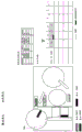
Fig. 1 is a schematic diagram showing the entire configuration of an automatic analyzer according to embodiment 1 of the present invention.
Fig. 2 is a diagram showing an initial state in a sample transfer process using the automatic analyzer according to embodiment 1 shown in fig. 1.
Fig. 3 is a view showing a state in which the 1 st rack is conveyed from the state shown in fig. 2.
Fig. 4 is a diagram showing a state in which a request for a sample at the 1 st rack is received by the operation unit from the state shown in fig. 3.
Fig. 5 is a diagram showing a situation where, from the situation shown in fig. 4, a planned wait for measurement items of the head of the dispensing request table is performed.
Fig. 6 is a view showing a state where measurement of the cycle on the dispensing schedule is started from the state shown in fig. 5.
Fig. 7 is a view showing a state of conveying the 2 nd rack from the state shown in fig. 6.
Fig. 8 is a view showing a state in which a request for a sample at the 2 nd rack is received by the operation unit from the state shown in fig. 7.
Fig. 9 is a view showing a state where a conveyance request for the sample rack of the 1 st rack is made from the state shown in fig. 8.
Fig. 10 is a view showing a state in which the sample rack of the 1 st rack is transported from the state shown in fig. 9.
Fig. 11 is a diagram showing a situation where, from the situation shown in fig. 10, a planned wait for measurement items of the head of the dispensing request table is performed.
Fig. 12 is a view showing a state where dispensing of the cycle on the dispensing schedule table is started from the state shown in fig. 11.
Fig. 13 is a view showing a state of confirming a sample to be measured next from the state shown in fig. 12.
Fig. 14 is a diagram showing a situation where, from the situation shown in fig. 13, a planned wait for measurement items of the head of the dispensing request table is performed.
Fig. 15 is a view showing a state where dispensing and measurement of the cycle on the dispensing schedule table are started from the state shown in fig. 14.
Fig. 16 is a diagram showing a situation in which a rack conveyance request is made from the situation shown in fig. 15.
Fig. 17 is a diagram showing a state in which the racks are transported from the state shown in fig. 16.
Fig. 18 is a view showing a state where dispensing of the cycle on the dispensing schedule table is started from the state shown in fig. 17.
Fig. 19 is a diagram showing an initial state in a case where a rack requiring an emergency is transported in a transport procedure of a sample using the automatic analyzer of embodiment 1 shown in fig. 1.
Fig. 20 is a view showing a state in which a request for the sample at the 1 st rack is received by the operation unit from the state shown in fig. 19.
Fig. 21 is a diagram showing a situation where, from the situation shown in fig. 20, a measurement item of the head of the dispensing request table is scheduled to wait.
Fig. 22 is a view showing a state where a conveyance request for the sample rack of the 1 st rack is made from the state shown in fig. 21.
Fig. 23 is a view showing a state in which the sample rack of the 1 st rack is transported from the state shown in fig. 22.
Fig. 24 is a diagram showing a situation where, from the situation shown in fig. 23, a planned wait for measurement items of the head of the dispensing request table is performed.
Fig. 25 is a diagram showing a situation where an urgent sample rack conveyance request is made from the situation shown in fig. 24.
Fig. 26 is a diagram showing a state in which the sample rack is urgently transported from the state shown in fig. 25.
Fig. 27 is a diagram showing a situation in which, from the situation shown in fig. 21, when a measurement item waiting for the head of the dispensing request table cannot be scheduled, a process of scheduling the measurement item again is added.
Fig. 28 is a schematic diagram showing the entire configuration of an automatic analyzer according to embodiment 2 of the present invention.
Detailed Description
Hereinafter, an automatic analyzer and a sample transfer method according to an embodiment of the present invention will be described with reference to the drawings.
< example 1 >
Example 1 of an automatic analyzer and a sample transfer method according to the present invention will be described with reference to fig. 1 to 27.
First, the entire configuration of the automatic analyzer according to the present embodiment will be described with reference to fig. 1. Fig. 1 is a schematic diagram showing the overall configuration of an automatic analysis apparatus according to the present embodiment.
The automatic analyzer (10) shown in fig. 1 is an apparatus for performing qualitative and quantitative analyses of biological samples such as blood and urine, and is mainly composed of a transport unit (101), an analysis unit (111), and an operation unit (121).
The transport unit (101) is a unit for delivering a sample rack (104) in which 1 or more sample containers containing biological samples such as blood and urine to be analyzed are loaded into the automatic analyzer (10), collecting the samples, and transporting the collected samples to the analysis unit (111).
The conveying unit (101) is provided with a rack buffer (103), a rack supply tray (102), a rack storage tray (107), a conveying line (106), and a conveying control part (105).
In the transfer unit (101), a sample rack (104) provided on a rack supply tray (102) is transferred to a rack buffer (103) via a transfer line (106). In the middle of the transfer line (106), there is a sensor (not shown) for determining the presence or absence of a sample, and the presence or absence of a sample container on the sample rack (104) is confirmed. Here, when it is determined that a sample container is present, a sample barcode reader (not shown) reads a sample barcode (not shown) attached to the sample container to obtain identification information of the sample. In practical systems, the patient is identified by the identification information.
The rack buffer (103) is a rotor structure that performs a circular motion, and has slots on the outer circumference thereof to radially hold a plurality of sample racks (104) on which a plurality of sample containers are mounted on a concentric circle. The slot is rotated by a motor, and thus, any sample holder (104) is carried in and out according to a requested destination. With this configuration, it is possible to eliminate the need to sequentially process the first-placed sample holders (104). That is, as long as the priority is high, it can be processed first.
A transfer line (106) is connected to a point on the radial circumference of the rack buffer (103) to carry in and out the sample rack (104). When the point is set to a position of 0 degree on the circumference, a sample dispensing line (112) for introducing an analysis unit (111) described later is connected to a position of 90 degrees on the circumference from the position connected by the transfer line (106), and the sample rack (104) is carried in and out.
The sample rack (104) that has finished dispensing in each analysis unit (111) is on standby in the rack buffer (103), and waits for the output of the measurement result, and if necessary, can be automatically re-checked. When the processing is finished, the workpiece is conveyed to the rack storage tray (107) through the conveying line (106).
The transport control unit (105) is a part that controls an operation of transporting an appropriate sample rack (104) from the rack buffer (103) to the sample dispensing line (112), an operation of returning the sample rack (104) from the sample dispensing line (112) to the rack buffer (103), and a transport operation for transporting a sample to the analysis unit (111) based on a transport request signal from a control unit (119) of the analysis unit (111) described later.
The operation unit (121) includes a display device (121a) for displaying an operation screen for specifying a measurement item for measuring a sample to be measured and an operation screen for confirming a measurement result, and a user interface such as an input device (121b) for inputting various instructions, and is a part that has a function of receiving information of all units of the automatic analyzer. The operation unit (121) is connected to the analysis unit (111) and the transport unit (101) by a wired or wireless network line.
The analysis unit (111) is a unit that performs a measurement operation for a measurement item requested by a sample and outputs a measurement result, and is connected to the conveyance unit (101). The analysis unit (111) includes a reaction disk (115), a reagent disk (117), a sample dispensing line (112), a reagent probe (116), a sample probe (113), a biochemical measurement unit (118), an electrolyte measurement unit (114), and a control unit (119).
Reaction vessels (not shown) are arranged in the circumferential direction of the reaction disk (115). A sample dispensing line (112) is provided near the reaction disk (115) to carry in a sample rack (104) on which sample containers are mounted.
A sample probe (113) is provided between the reaction disk (115) and the sample dispensing line (112) so as to be rotatable and vertically movable. The sample probe (113) moves while drawing an arc about a rotation axis to dispense a sample from the sample holder (104) into a reaction vessel.
The reagent disk 117 is a storage container on which a plurality of reagent bottles (not shown) containing reagents therein can be placed on the circumference. The reagent disk (117) is refrigerated.
A reagent probe 116 is provided between the reaction disk 115 and the reagent disk 117 so as to be rotatable and vertically movable. The reagent probe 116 moves while drawing an arc about the rotation axis, enters the reagent disk 117 from the reagent probe suction port, and dispenses a reagent from the reagent bottle to the reaction vessel.
Furthermore, washing tanks (not shown) are provided in the operation ranges of the reagent probe (116) and the sample probe (113), respectively.
Around the reaction disk (115), an electrolyte measurement unit (114) and a biochemical measurement unit (118) are further disposed.
The electrolyte measurement unit (114) is an analysis unit that measures the concentration of an electrolyte in a sample using an ion selective electrode. The electrolyte measurement unit (114) is an analysis unit that is required to perform a pre-measurement operation for measuring the electromotive force of an internal standard solution of a known concentration prior to dispensing a sample.
The biochemical measurement unit (118) is an analysis unit for measuring the absorbance of a reaction solution produced by mixing and reacting in a reaction vessel on the reaction disk (115) and analyzing a biochemical component in a sample, and is formed of a light source, a spectrophotometer, and the like. The biochemical measuring unit (118) is an analyzing unit which does not require a pre-measurement operation as in the electrolyte measuring unit (114).
A control unit (119) disposed in the analysis unit (111) is connected to each mechanism in the analysis unit (111) and controls the operation thereof.
In particular, in the control unit (119) of the present embodiment, even when the sample is still present in the transport unit (101), the analysis unit (111) is caused to perform the pre-measurement operation required before the sample is aspirated for each measurement method, and before the time when the aspiration operation is started for the sample, the control unit controls the respective mechanisms in the analysis unit (111) to transport the sample to the analysis unit (111), and outputs a control signal to the transport control unit (105) in the transport unit (101).
The control unit (119) of the present embodiment acquires in advance the time required for transport from the transport control unit (105) to the transport unit (101), determines the timing for starting transport of the sample based on the planned operation time for dispensing the sample and the time required for transporting the sample from the transport unit (101) to the analysis unit (111), and starts transport of the sample at the optimum time for each of the connected transport units (101).
Further, the control unit (119) of the present embodiment executes a dispensing operation for a different sample during the execution of the pre-measurement operation for the sample on standby in the conveyance unit (101).
Details of these operations will be described later in detail with reference to the drawings following fig. 2.
Next, the schematic operation of the mechanism of the automatic analyzer (10) shown in fig. 1 will be described.
A transfer unit (101) transfers sample racks (104) set on rack supply trays (102) of an automatic analyzer (10) to a transfer line (106) one by one and then to a rack buffer (103). The sample rack (104) conveyed to the rack buffer (103) is conveyed to a sample dispensing line (112) of an analysis unit (111).
When a sample rack (104) reaches a sample dispensing line (112) of an analysis unit (111), a dispensing operation is performed on each sample mounted on the sample rack (104) by a sample probe (113) according to a requested measurement item via an operation unit (121).
When the measurement item is a biochemical item, the sample probe (113) adds the aspirated sample to a reaction vessel on the reaction disk (115), and further adds a reagent aspirated from the reagent disk (117) to the reaction vessel via the reagent probe (116), and stirs the reagent. Thereafter, the absorbance is measured by a biochemical measuring unit (118), and the measurement result is output to an operation unit (121).
When the required measurement item is an electrolyte item, the sample probe (113) adds the aspirated sample to an electrolyte measurement unit (114), measures the electromotive force of the electrolyte measurement unit (114), and outputs the measurement result to the operation unit (121).
The operation unit (121) calculates the concentration of the specific component in the sample by arithmetic processing based on the received measurement result.
Next, the flow of analyzing a sample including a method of transporting the sample in the automatic analyzer 10 according to the present embodiment will be described with reference to fig. 2 to 27. Fig. 2 to 27 are diagrams illustrating how a sample is transported by the automatic analyzer according to the present embodiment.
Fig. 2 shows the automatic analyzer 10 of fig. 1, in which "rack ID: n0001 "," shelf ID: n0002' in the sample holder (104). "shelf ID: n0001 "is provided with 1" sample ID: 001 ", rack ID: n0002 "is provided with 1" specimen ID: sample 002 ". Further, the operation unit (121) performs a process for determining a "sample ID: 001 "," sample ID: 002 "requests analysis of electrolyte items and biochemical items, respectively.
In this state, the measurement of the apparatus is started, and as shown in fig. 3, the conveyance control unit (105) of the conveyance unit (101) sets a "rack ID: the N0001' sample rack 104 is transported to a transport line 106, and the ID attached to the sample rack 104 or a sample mounted thereon is read and transported to a rack buffer 103.
Thereafter, the conveyance control unit (105) of the conveyance unit (101) compares the read rack ID: n0001 "and sample" sample ID: 001' is notified to the operation unit (121).
The operation unit (121) receives, based on the received rack ID: n0001 "and" specimen ID: 001 "to specify the target sample and the measurement items required for the sample.
According to the conventional automatic analysis device, at this stage, the operation unit (121) instructs the conveyance unit (101) to move "shelf ID: the N0001' sample rack (104) is transported to an analysis unit (111). In contrast, in the automatic analyzer 10 of the present embodiment, as shown in fig. 4, first, the analysis unit (111) is notified of the measurement items required for each sample.
In the present description, the conveyance unit (101) is not notified, but the sample rack (104) is notified that the sample rack is expected to move to the analysis unit (111).
When the control unit (119) of the analysis unit (111) receives the "shelf ID: sample ID of N0001 ": 001' is requested, the sample is stored in the waiting dispensing request table (401) in the analysis unit (111) for waiting dispensing. In an analysis unit (111), for each analysis cycle of the device, a series of operations of a new measurement item for each cycle is planned.
In the present description, a series of operations are scheduled for a measurement item located at the head with reference to the waiting dispensing request table (401) at the start time of each cycle, but the present invention is not limited thereto, and a method of scheduling a plurality of measurement items at a time of a certain cycle may be used.
Thereafter, in the present embodiment, as shown in fig. 5, the control unit (119) of the analysis unit (111) refers to the waiting dispensing request table (401) at the start time of the 1 st cycle, and plans the "sample ID: 001 "in the electrolyte item.
At this time, "sample ID: 001 "sample holder" holder ID: n0001 "is still located on the handling unit (101) and not on the computer of the analysis unit (111). However, in the present invention, even if the sample is not in the state of the computer of the analyzing unit (111), the plan of the measurement operation is previously performed, and a series of operations of the measurement is reserved.
As described above, the electrolyte items cannot be measured from the start of sample dispensing, and the internal standard solution needs to be measured as the pre-measurement operation and the post-measurement operation. Therefore, as shown in the analysis schedule (501) of fig. 5, the operation before the measurement is performed in the 1 st cycle, the sample dispensing is performed in the 2 nd cycle, and the operation after the measurement is performed in the 3 rd cycle are planned.
Thereafter, as shown in fig. 6, when the control unit (119) of the analysis unit (111) reaches the "sample ID: 001' of the electrolyte items, even if the sample is not present in the analyzing unit (111) or is present in the transporting unit (101), the "sample ID: 001 ″ of the electrolyte items. This step corresponds to a pre-measurement operation for causing the analysis unit (111) to perform each measurement method that needs to be performed before the sample is aspirated.
On the other hand, as shown in fig. 7, on the conveying unit (101) side, since the "rack ID: when the N0001' loading is completed, the next sample rack (104) is loaded independently of the state of the analysis unit (111).
A conveyance control unit (105) of a conveyance unit (101) supplies a rack to a rack ID: the sample rack (104) of N0002' is sent to a transport line (106), and the ID attached to the sample rack (104) or a sample mounted therein is read and transported to a rack buffer (103). Thereafter, with "shelf ID: n0001 ", similarly, the sample rack" rack ID: n0002 "and sample" sample ID: 002' information is reported to the operation unit (121).
The operation unit (121) receives, based on the received rack ID: n000 "and" specimen ID: 002 "specifies the target sample and the measurement item requested by the sample. Similarly, instead of instructing the transport unit (101) to transport the sample to the analysis unit (111) by the operation unit (121), the analysis unit (111) is first notified of the measurement items requested for each sample, as shown in fig. 8.
When the control unit (119) of the analysis unit (111) receives the "shelf ID: sample ID of N0002 ": 002', the measurement items requested are stored in the waiting dispensing request table (401) for waiting dispensing of the sample in the analyzing unit (111).
On the other hand, as shown in fig. 9, the control unit (119) of the analysis unit (111) performs "sample ID: 001' is operated before the measurement, and whether or not the optimal time for requesting the transfer of the sample has arrived is monitored in accordance with the scheduled time for dispensing the next scheduled sample, thereby controlling the arrival of the sample from the transfer unit (101).
The optimum time here means a time obtained by subtracting a time required for transport from the transport unit (101) until the sample is transported in the system from a planned scheduled dispensing time of the sample.
Since the sample rack (104) is transferred between different computers, a preparation time can be added in consideration of time consumption of communication and the like.
The required transport time may be fixedly defined in the analysis unit (111), but depending on the configuration of the transport unit (101), it is preferably calculated by adding the time from the reception of the message from the transport control unit (105) of the transport unit (101) to the reception time from the transport unit (101) when the analysis unit (111) is activated.
As described above, when the optimal time for making a sample transfer request arrives, the control unit (119) of the analysis unit (111) uses the "sample ID: 001' is not present in the self unit, and instructs the transport unit (101) to transfer the "sample ID: 001 "mounted rack ID: n0001' is carried in. This step corresponds to a step of controlling the transport unit (101) to transport the sample to the analysis unit (111).
When the transport request from the analysis unit (111) is received by the transport control unit (105) of the transport unit (101), as shown in fig. 10, the "rack ID: n0001' is transported to the analysis unit (111). The analysis unit (111) receives the rack ID: n0001' is conveyed to a sample suction position of the sample probe (113).
On the other hand, as shown in fig. 11, since the cycle 2 is entered, the control unit (119) of the analysis unit (111) refers to the waiting dispensing request table (401) at the start of the cycle 2, and plans the "sample ID: 001 "in the biochemical project. .
Since the biochemical items start from the sample dispensing as described above, operations prior to the measurement of the electrolyte items are not required, and the 3 rd cycle is planned after the sample dispensing of the electrolyte item in the 2 nd cycle as in the analysis plan table (501) of fig. 11.
Thereafter, as shown in fig. 12, in the control unit (119) of the analysis unit (111), since the "sample ID: 001 ", and when sample dispensing is started, the" sample ID: the 001' sample is transported to the suction position of the sample probe (113), and therefore the target sample can be sucked.
Thereafter, as shown in fig. 13, when the "sample ID: when the sample suction of the electrolyte item of 001 ″ is finished, similarly, whether or not the optimum timing for the next transfer request for dispensing the sample is reached is monitored.
When the optimum time for carrying the sample arrives, the analysis unit (111) uses the' sample ID: 001' already exists in the self-unit, and in this case, the sample is maintained as it is without sending a request for carrying in the rack to the carrying unit (101).
On the other hand, as shown in fig. 14, since the cycle 3 is entered, the control unit (119) of the analysis unit (111) refers to the waiting dispensing request table (401) at the start of the cycle 3, and plans the "sample ID: 002 "of the electrolyte items.
Since the electrolyte items are electrolyte items, as shown in the analysis schedule table (501) of fig. 5, the operation before the measurement is performed in the 3 rd cycle, the sample dispensing is performed in the 4 th cycle, and the operation after the measurement is performed in the 5 th cycle are planned.
Thereafter, as shown in fig. 15, in the control unit (119) of the analysis unit (111), since the "sample ID: 001' of the electrolyte items, the start time of the operation after measurement is performed by the electrolyte measurement unit (114).
In parallel with this, since the "sample ID: 001 ″ of the biochemical item, sample dispensing is started. Since the sample is the same as the sample already at the suction position of the sample probe (113), the target sample can be sucked.
Further, in parallel, since the "specimen ID: the start time of the operation before measurement of the electrolyte item of "002", the sample ID: 002 "electrolyte item.
In addition, when the present invention is used, as shown in fig. 15, "sample ID: 002 "sample is not present in the computer of the analyzing unit (111), and different" sample ID: 001 ", and further, even if the sample is sucked, the" sample ID: 002 "electrolyte item.
Thereafter, as shown in fig. 16, when the "sample ID: when the sample suction of the biochemical item of 001 ″ is finished, similarly, whether or not the optimum timing for the next transfer request for dispensing the sample is reached is monitored.
When the optimal time for making a sample transport request is reached, the control unit (119) of the analysis unit (111) causes the "sample ID: 002 "does not exist in the own unit, and the carrier unit (101) is given a" rack ID: n0001 "returns, and the sample ID: the "shelf ID of 002": indication of N0002 ". This step also corresponds to a step of controlling the transport unit (101) to transport the sample to the analysis unit (111).
When the transport request from the analysis unit (111) is received by the transport control unit (105) of the transport unit (101), as shown in fig. 17, the "rack ID: n0001 "and" shelf ID: n0002' is conveyed to the analysis unit (111). The analysis unit (111) receives the rack ID: n0002' is conveyed to the sample suction position of the sample probe (113).
Thereafter, as shown in fig. 18, since the "sample ID: the sample dispensing start time of the electrolyte item "002" is set to "sample ID: the sample (002') is transported to the suction position of the sample probe (113), so that the target sample can be sucked.
Next, in the automatic analyzer (10) shown in fig. 1, a case where a sample for which an urgent request is additionally input is measured with respect to a normal sample will be described with reference to fig. 19 to 27.
Fig. 19 shows an automatic analyzer (10) having the configuration of fig. 1, in which a "rack ID: e0001' sample rack (1901) is mounted on the rack supply tray (102). "shelf ID: in the sample holder (1901) of E0001 ", 1" specimen ID: 003'. Further, a "sample ID: 003 "only biochemical items are required.
In order to cope with this, it is preferable to add a column of priority to the waiting dispensing request table (401).
In this case, as shown in fig. 20, the conveyance controller (105) of the conveyance unit (101) causes the "rack ID: after the loading of N0002 ", a rack ID: an emergency sample rack (1901) of E0001' is conveyed to a conveying line (106), and the ID attached to the sample rack (104) and the sample loaded therein is read and conveyed to a rack buffer (103).
Thereafter, the conveyance controller (105) transfers the read sample rack "rack ID: e0001 "and sample" sample ID: 003' to the operation unit (121).
On the basis of the received rack ID: e0001 "and" specimen ID: 003 ", the target sample and the measurement item requested by the sample are specified. Similarly, as shown in fig. 20, the analysis means (111) is notified of the measurement items requested for each sample.
Here, when the operation unit (121) recognizes "sample ID: 003 ' is an essential sample, the priority of the measurement item notified by the analysis unit (111) is ' high ', and the sample is transferred.
In the present description, a method of notifying the analyzing unit (111) of the priority of the sample from the operation unit (121) is used, but the present invention is not limited to this, and for example, the analyzing unit (111) may recognize that the rack ID requested by the request is a rack ID of an important type, and the priority of the sample is high.
When the control unit (119) of the analysis unit (111) receives the "shelf ID: sample ID of E0001 ": 003' the requested measurement item, the waiting dispensing of the sample in the analyzing unit (111) is stored in the waiting dispensing request table (401).
At this time, the control unit (119) compares the priority of the measurement item with the priority of the measurement item already registered in the waiting dispensing request table (401). In this case, the priority of the current urgent sample is the highest, and the urgent sample is stored in the head of the waiting dispensing request table (401).
Thereafter, as shown in fig. 21, since the cycle 2 has already been entered, the control unit (119) of the analysis unit (111) schedules a series of operations for the measurement items located on the head with reference to the waiting dispensing request table (401) at the start of the cycle 2.
Specifically, the measurement items of the header are the above-mentioned critical samples "sample ID: 003', the control unit (119) plans the measurement items in the same manner as a normal method. This makes it possible to easily switch to the critical sample without adding any special processing. In this case, sample dispensing is scheduled in the 3 rd cycle as in the analysis schedule (501) of fig. 21.
Thereafter, as shown in fig. 22, the control unit (119) of the analysis unit (111) performs the analysis for "sample ID: when sample suction for the electrolyte item of 001 ″ is completed, whether or not the optimum timing for carrying a next predetermined sample dispensing request has arrived is similarly monitored. Here, when the next sample is confirmed, the "rack ID: sample ID of E0001 ": 003".
When the optimum time for the sample transfer request is reached, the "sample ID: 003' is not in the self-cell, the control unit (119) of the analysis unit (111) issues to the transport control unit (105) of the transport unit (101) "a rack ID: n0001 "returns, and" sample ID: 003 "shelf ID mounted: e0001 ", thereby connecting" specimen ID: 003' the sample is sucked and transferred to the sample probe (113).
In this case, the "sample ID: 003' can be easily switched to the critical sample without adding any special treatment.
Thereafter, as shown in fig. 24, the control unit (119) of the analysis unit (111) enters the 3 rd cycle, and when the 3 rd cycle starts, it refers to the waiting dispensing request table (401) and schedules a series of operations for the measurement items located at the head.
Specifically, the "sample ID: 0' and the control unit (119) plans the measurement items in a normal manner. This makes it possible to easily switch to a sample scheduled to be inserted because it is an essential sample without requiring special processing. In this case, sample dispensing in the 4 th cycle is scheduled as in the analysis schedule table (501) of fig. 24.
Thereafter, the time advances, and as shown in fig. 25, the control unit (119) of the analysis unit (111) performs the analysis when the "sample ID: 003 ″, it is monitored whether or not the optimum timing for the next transfer request for dispensing the sample has arrived. Here, when the next sample is confirmed, it becomes the "rack ID: sample ID of N0001 ": 001".
When the optimal time for making a sample transport request is reached, the control unit (119) of the analysis unit (111) uses the "sample ID: 001' is not in the self-unit, and a carrier control unit (105) of the carrier unit (101) transmits a current rack ID: e0001 "returns, and" sample ID: 001 "mounted rack ID: n0001 ", thereby" specimen ID: 001' to the sample of the sample probe (113).
In this case, the "sample ID: 001' can be easily switched to an essential sample without adding any special treatment.
According to the method of the present embodiment, since the operations of carrying in, carrying out, and retracting the sample from the independent transport unit (101) to the analysis unit (111) can be flexibly realized, the following method can be adopted as an extension thereof.
For example, fig. 27 shows a case where, at the start of the 2 nd cycle in fig. 21, an attempt is made to wait for an important sample "sample ID" at the head of the dispensing request table (401): 003 ", for example, the biochemical items interfere with the analysis items of other samples in a series of measurement operations, and the" sample ID: 003 ".
In general, when it is determined that the critical sample is to be inserted at the previous stage, it is difficult to stop the carrying-in of the critical sample suddenly depending on the situation of the analysis unit (111).
On the other hand, in the case of the present example, with further reference to the next measurement item, only the planning process is similarly added, and the "sample ID: 001' sample measurement item can delay the insertion of the critical sample to the next cycle. This prevents the occurrence of a null cycle in which sample dispensing is unnecessary, and therefore, a high throughput can be maintained.
Next, the effects of the present embodiment will be described.
The automatic analyzer (10) according to embodiment 1 of the present invention includes an analyzing unit (111) for measuring a sample, a transporting unit (101) for transporting the sample to the analyzing unit (111), and a control unit (119), wherein the control unit (119) controls the analyzing unit (111) and the transporting unit (101) such that the analyzing unit (111) performs pre-measurement operations of the respective measurement methods that are required before the sample is aspirated, even in a state where the sample is still present in the transporting unit (101), and the sample is transported to the analyzing unit (111) before a time when the aspiration operation of the sample is started.
By such control, even if 2 or more analysis units (111) having different sample dispensing times for measurement items are provided in the measurement device, the analysis procedure is not changed, and a sample rack (104) having sample containers containing samples is supplied from the transport unit (101) at the optimum timing according to the measurement method without providing a position or a special mechanism for waiting the samples, and the analysis operation can be started. On the side of the transport unit (101), the sample can be supplied to the analysis unit (111) at the optimum timing for the measurement items of each analysis unit (111), independently of the measurement method of the analysis unit (111).
Therefore, the transport unit (101) can be connected to the analysis unit (111) of any configuration. That is, compared with the conventional system, it is possible to easily realize a flexible system configuration according to the installation position and the application.
In addition, since no special mechanism or a position for waiting the sample is added to the analysis unit (111), the automatic analyzer 10 can be reduced in space and cost.
Further, according to the present invention, it is possible to easily realize flexible change of the supply timing and order of the samples. Therefore, when the critical sample is input, in the case of the configuration of the conventional automatic analyzer, in the analyzing unit (111) connected to the independent transport unit (101), it is difficult to perform complicated transfer and cancellation of the sample between the transport unit (101) and the analyzing unit (111), and on the contrary, the sample scheduled to be scheduled can be cancelled and switched to the immediate measurement of the critical sample, and TAT (Turn Around Time) in the emergency inspection can be shortened as compared with the conventional one.
The control unit (119) determines the timing at which the sample starts to be transported based on a predetermined time for dispensing the sample planned in advance and the time required for transporting the sample from the transport unit (101) to the analysis unit (111), and can transport the sample rack (104) to the analysis unit (111) at a more appropriate timing.
Further, since the control unit (119) causes a different sample to perform a dispensing operation during a pre-measurement operation for a sample waiting in the conveyance unit (101), the idle time can be reduced compared to the prior art, the sample analysis operation can be performed more efficiently, and the analysis efficiency can be improved.
In addition, the control unit (119) receives the time required for the conveyance of the conveyance unit (101) in advance, and starts the conveyance of the sample at the optimum time for each of the conveyance units (101) connected, so that even when the configuration of the automatic analysis device (10) is changed to connect to a different conveyance unit, the conveyance request of the sample can be made at the optimum time without changing the configuration of the analysis unit (111). Therefore, a flexible configuration corresponding to the processing capability required of the analysis apparatus can be more easily constructed.
Furthermore, when there are 2 or more biochemical measuring units (118) and electrolyte measuring units (114) in 1 analyzing unit (111), and the electrolyte measuring unit (114) which is different in measuring method, particularly, which requires an operation before measurement, and the biochemical measuring unit (118) which does not require an operation before measurement, the effect of combining the timings required for dispensing the samples of the respective measurement items of the analyzing unit (111) and carrying them can be exhibited to the maximum.
In addition, the control unit (119) is disposed in the analysis unit (111), so that a system capable of performing control necessary for the transport of the sample in the analysis unit (111) can flexibly cope with the change of the configuration of the automatic analysis device (10).
Further, the automatic analyzer is provided with a transport control unit (105) disposed in the transport unit (101) to control the transport operation of transporting the sample to the analysis unit (111) based on a transport request signal from the control unit (119), so that the control in the transport unit (101) can be completed in the transport unit (101), and the automatic analyzer can flexibly respond to the change of the configuration of the automatic analyzer (10).
Further, the sample processing device further includes a rack buffer (103) having a rotor structure disposed in the transfer unit (101) to radially hold the plurality of sample racks (104) on a concentric circle, so that the analysis unit (111) can perform the transfer processing of arbitrary sample racks (104) in different orders without requiring a complicated configuration.
Further, by providing an operation unit (121) that integrates the entire information of the automatic analyzer (10) and is independent of the control unit (119), the control on the control unit (119) side of the analysis unit (111) and the like can be limited to only adjustment of the operation procedure in the analysis unit (111), and the configuration of the control unit can be simplified. As a result, miniaturization is facilitated, and cost reduction can be achieved.
In the automatic analyzer (10) of the present embodiment, the biochemical items and the electrolyte items are concentrated in 1 analyzing unit (111) as an example, but the present invention is not particularly limited thereto, and an analyzing unit having any configuration may be used.
The sample dispensing cycles of the electrolyte measurement unit (114) and the biochemical measurement unit (118) are each described as 1 cycle, but the dispensing cycles are not particularly limited thereto, and may be different from each other. In this case, in the next scheduled sample dispensing operation, the time required for conveyance in the system is subtracted from the scheduled time for sample aspiration, and the time when this time is reached is monitored, and conveyance of the sample rack (104) may be instructed.
In addition, not only the number of sample dispensing cycles but also the time taken until the start of sample aspiration and the time taken for aspiration of the sample may be different. In this case, as described above, it is possible to cope with the measurement item planning by merely adding confirmation that the difference between the end of sample suction in sample dispensing of the previous measurement item and the start of sample suction in sample dispensing of the measurement item measured this time is insufficient for the conveyance of the measurement item. In this case, if the required time is not sufficient for the conveyance, the plan may be performed again in the next cycle.
< example 2 >
An automatic analyzer and a sample transfer method according to example 2 of the present invention will be described with reference to fig. 28. Fig. 28 is a schematic diagram of the automatic analyzer of the present embodiment. The same components as those in example 1 are denoted by the same reference numerals, and the description thereof is omitted.
As shown in fig. 28, the automatic analyzer (10A) of the present embodiment adds an analysis unit (131) for immune item measurement to the automatic analyzer (10) shown in fig. 1.
The analysis unit (131) is a unit that performs a measurement operation of a measurement item required for a sample and outputs a measurement result, similarly to the analysis unit (111), and includes an incubator (134), a reagent disk (135), a sample dispensing line (132), a reagent probe (136), a sample probe (133), an immunoassay unit (137), and a control unit (138).
The incubator (134) is a tray for performing a reaction between a sample and a reagent at a constant temperature.
The immunoassay unit (137) is an analysis section for mixing and reacting a reagent and a sample in a reaction vessel (not shown) mounted on an incubator (134) and analyzing a minor component in blood such as a hormone in the sample with high sensitivity.
In the analyzing unit (131), a reagent is usually dispensed into a reaction vessel on an incubator (134) first, and the immunoassay unit (137) is an analyzing unit that requires a pre-measurement operation.
Even in a state where a sample is still present in the transport unit (101A), the control unit (138) causes the analysis unit (131) to perform a reagent dispensing operation, controls the mechanisms in the analysis unit (131) so that the sample is transported to the analysis unit (131) before the time when the sample aspiration operation is started, and outputs a control signal to the transport control unit (105A) in the transport unit (101A). The other operations are substantially the same as those of the control unit (119) of the analysis unit (111), and therefore, the details thereof are omitted.
The reagent disk (135), the sample dispensing line (132), the reagent probe (136), and the sample probe (133) are substantially the same in structure and operation as the reagent disk (117), the sample dispensing line (112), the reagent probe (116), and the sample probe (113) of the analysis unit (111), respectively, and the details thereof are omitted.
Since the analyzing unit (111) having the biochemical measuring unit (118) and the analyzing unit (131) having the immunoassay unit (137) have different analyzing steps, the analyzing unit controls the mechanism to perform the analysis on the schedules defined by the different analyzing periods, and performs the analyzing processes in parallel with each other at the different analyzing periods.
In the case where the analyzing units having different analyzing periods are connected to each other as in the present embodiment and used as an integrated analyzing apparatus, it is necessary to absorb the difference in the analyzing periods.
When the analysis units (111, 131) are transported and carried into the sample rack (104), first, the transport controller (105A) outputs the synchronization signals to all of the plurality of analysis units (111, 131) with an output time difference of 1 to 1 of the number of connected analysis units (111, 131) in 1 operation cycle. When it takes time to transport a sample rack (104) in the unit, the control unit (119) and the control unit (138) output a transport request signal for the sample rack (104) to the transport control unit (105) within a predetermined time period after the input of the synchronization signal, and execute transport control of the sample rack (104).
On the other hand, when the sample rack (104) is not required to be transported, the control unit (119) and the control unit (138) disregard the input synchronization signal.
The other configurations and operations are substantially the same as those of the automatic analyzer and the sample transfer method according to embodiment 1, and the details thereof are omitted.
In the automatic analyzer (10A) and the sample transfer method of embodiment 2 of the present invention, which have at least 2 analyzing units (111, 131) that analyze different measurement items and have different transfer destinations, almost the same effects as those of the automatic analyzer (10) and the sample transfer method of embodiment 1 can be obtained.
< Others >
The present invention is not limited to the above-described embodiments, and includes various modifications. The above-described embodiments are for easy understanding of the present invention, and are not limited to having all the configurations described.
In addition, a part of the configuration of one embodiment may be replaced with the configuration of another embodiment, and the configuration of one embodiment may be added to the configuration of another embodiment. Further, a part of the configuration of each embodiment may be added, deleted, or replaced with another configuration.
Description of the reference numerals
10. An automatic analyzer 10a …, 101a … transport unit, 103a … rack buffer, 104 … sample rack, 105a … transport control unit, 111, 131 … analysis unit, 114 … electrolyte measurement unit (1 st measurement unit), 118 … biochemical measurement unit (2 nd measurement unit), 119, 138 … control unit, 121 … operation unit (integrated control unit), 137 … immunoassay unit (1 st measurement unit), 401 … analysis unit in-cell waiting dispensing request table, 501 … analysis unit in-cell dispensing schedule table, 1901 … emergency sample rack.
Claims (13)
1. An automatic analyzer for analyzing a sample, comprising:
an analysis unit for measuring the sample,
a transport unit that transports the sample to the analysis unit,
and a controller that controls the analyzing unit and the conveying unit so that the analyzing unit performs a pre-measurement operation that needs to be performed before the sample is aspirated in each measurement method even in a state where the sample is still present in the conveying unit, and conveys the sample to the analyzing unit before a timing at which the aspiration operation is started for the sample.
2. The automatic analyzer according to claim 1, wherein the controller determines the timing to start the transfer of the sample based on a scheduled operation time for dispensing the sample and a time required to transfer the sample from the transfer unit to the analyzer.
3. The automatic analyzer according to claim 1, wherein the controller causes a dispensing operation for a different sample to be executed during a pre-measurement operation for the sample waiting in the transport unit.
4. The automatic analyzer according to claim 1, wherein the controller starts the transfer of the sample at an optimum time for each of the connected transfer units by a time required for the transfer of the transfer unit received in advance.
5. The automatic analyzer according to claim 1, wherein 2 or more measuring devices are present in 1 analyzer unit.
6. The automatic analyzer according to claim 5, wherein the measurement methods of the 2 or more measurement devices in the 1 analysis unit are different.
7. The automatic analyzer according to claim 6, wherein the different measuring devices in the 1 analyzing unit are constituted by at least a 1 st measuring device requiring a pre-measurement operation and a 2 nd measuring device not requiring the pre-measurement operation.
8. The automatic analyzer according to claim 1, comprising at least 2 of the analyzing units that analyze different measurement items with different transport destinations.
9. The automatic analyzer according to claim 1, wherein the controller is disposed in the analysis unit.
10. The automatic analyzer according to claim 1, further comprising a transport controller disposed in the transport unit and configured to control a transport operation for transporting the sample to the analyzer based on a transport request signal from the controller.
11. The automatic analyzer according to claim 1, further comprising a rack buffer having a rotor structure, the rack buffer being disposed in the transport unit and radially holding a plurality of sample racks each having a sample container for containing the sample thereon on a concentric circle.
12. The automatic analyzer according to claim 1, further comprising a comprehensive controller that integrates information of the entire automatic analyzer, independently of the controller.
13. A method for transporting a sample to an automatic analyzer for analyzing the sample, the automatic analyzer comprising an analyzing unit for measuring the sample, a transporting unit for transporting the sample to the analyzing unit, and a control unit for controlling a transporting timing of the sample based on an analysis schedule created by the analyzing unit,
the method comprises the following steps:
even in a state where the sample is still present in the carrying unit, the analysis unit is caused to perform a pre-measurement operation that needs to be performed before the sample is aspirated in each measurement method, and
and controlling the transport unit to transport the sample to the analysis unit before a timing at which the sample aspiration operation is started.
Applications Claiming Priority (3)
| Application Number | Priority Date | Filing Date | Title |
|---|---|---|---|
| JP2018-108636 | 2018-06-06 | ||
| JP2018108636A JP7010768B2 (en) | 2018-06-06 | 2018-06-06 | Automatic analyzer and sample transfer method |
| PCT/JP2019/019476 WO2019235158A1 (en) | 2018-06-06 | 2019-05-16 | Automated analysis device, and method for conveying sample |
Publications (2)
| Publication Number | Publication Date |
|---|---|
| CN112166327A true CN112166327A (en) | 2021-01-01 |
| CN112166327B CN112166327B (en) | 2024-05-31 |
Family
ID=68770373
Family Applications (1)
| Application Number | Title | Priority Date | Filing Date |
|---|---|---|---|
| CN201980033253.XA Active CN112166327B (en) | 2018-06-06 | 2019-05-16 | Automatic analysis device and sample transport method |
Country Status (5)
| Country | Link |
|---|---|
| US (1) | US11971423B2 (en) |
| EP (1) | EP3805765B1 (en) |
| JP (1) | JP7010768B2 (en) |
| CN (1) | CN112166327B (en) |
| WO (1) | WO2019235158A1 (en) |
Families Citing this family (2)
| Publication number | Priority date | Publication date | Assignee | Title |
|---|---|---|---|---|
| US12241905B2 (en) | 2019-03-11 | 2025-03-04 | Hitachi High-Tech Corporation | Automatic analysis device and automatic analysis method |
| CN112415187B (en) * | 2020-11-26 | 2024-11-19 | 南京国科精准医学科技有限公司 | A homogeneous immunoassay analyzer |
Citations (8)
| Publication number | Priority date | Publication date | Assignee | Title |
|---|---|---|---|---|
| CN101147071A (en) * | 2005-04-01 | 2008-03-19 | 株式会社三菱化学药得论 | Automatic analyzer and method for analyzing biological sample, and cuvette |
| JP2009036723A (en) * | 2007-08-03 | 2009-02-19 | Olympus Corp | Automatic analysis apparatus and operation environment setting method |
| JP2010197048A (en) * | 2009-02-20 | 2010-09-09 | Toshiba Corp | Autoanalyzer |
| JP2010281634A (en) * | 2009-06-03 | 2010-12-16 | Hitachi High-Technologies Corp | Dispensing planning method and dispensing planning apparatus for sample processing system |
| CN102378915A (en) * | 2009-04-09 | 2012-03-14 | 株式会社日立高新技术 | Autoanalyzer and dispensing apparatus |
| WO2014127379A1 (en) * | 2013-02-18 | 2014-08-21 | Theranos, Inc. | Systems and methods for multi-analysis |
| CN104350386A (en) * | 2012-06-11 | 2015-02-11 | 株式会社日立高新技术 | Automatic analysis device |
| CN107850612A (en) * | 2015-09-11 | 2018-03-27 | 株式会社日立高新技术 | Automatic analysis device |
Family Cites Families (15)
| Publication number | Priority date | Publication date | Assignee | Title |
|---|---|---|---|---|
| JP2988362B2 (en) * | 1996-03-11 | 1999-12-13 | 株式会社日立製作所 | Multi-sample analysis system |
| JP3930977B2 (en) * | 1998-07-31 | 2007-06-13 | 株式会社日立製作所 | Sample processing system |
| JP2001004636A (en) | 1999-06-18 | 2001-01-12 | Hitachi Ltd | Automatic analyzer |
| JP3830836B2 (en) | 2002-03-07 | 2006-10-11 | 株式会社日立ハイテクノロジーズ | Automatic analyzer |
| JP4110101B2 (en) * | 2004-01-28 | 2008-07-02 | 株式会社日立ハイテクノロジーズ | Automatic analyzer |
| JP4805710B2 (en) * | 2006-03-31 | 2011-11-02 | シスメックス株式会社 | Sample analyzer |
| WO2008050396A1 (en) | 2006-10-24 | 2008-05-02 | Olympus Corporation | Analyzer |
| JP5075790B2 (en) | 2008-10-31 | 2012-11-21 | 株式会社日立ハイテクノロジーズ | Sample test pretreatment system and sample test pretreatment method |
| JP5523723B2 (en) | 2009-03-13 | 2014-06-18 | 株式会社東芝 | Automatic analyzer |
| US20120177536A1 (en) | 2009-09-18 | 2012-07-12 | Chiki Sakai | Automatic analyzer |
| JP2012173251A (en) | 2011-02-24 | 2012-09-10 | Sysmex Corp | Sample analysis device and sample analysis method |
| WO2013070740A1 (en) | 2011-11-07 | 2013-05-16 | Beckman Coulter, Inc. | Aliquotter system and workflow |
| JP5782395B2 (en) | 2012-02-28 | 2015-09-24 | 株式会社日立ハイテクノロジーズ | Array generation method and array generation apparatus |
| WO2014119378A1 (en) | 2013-01-30 | 2014-08-07 | 株式会社 日立ハイテクノロジーズ | Centrifuging system, sample preprocessing system, and control method |
| JP6580869B2 (en) | 2015-05-29 | 2019-09-25 | シスメックス株式会社 | Sample analyzer, transport device, and method |
-
2018
- 2018-06-06 JP JP2018108636A patent/JP7010768B2/en active Active
-
2019
- 2019-05-16 EP EP19814225.9A patent/EP3805765B1/en active Active
- 2019-05-16 US US17/052,828 patent/US11971423B2/en active Active
- 2019-05-16 CN CN201980033253.XA patent/CN112166327B/en active Active
- 2019-05-16 WO PCT/JP2019/019476 patent/WO2019235158A1/en not_active Ceased
Patent Citations (9)
| Publication number | Priority date | Publication date | Assignee | Title |
|---|---|---|---|---|
| CN101147071A (en) * | 2005-04-01 | 2008-03-19 | 株式会社三菱化学药得论 | Automatic analyzer and method for analyzing biological sample, and cuvette |
| JP2009036723A (en) * | 2007-08-03 | 2009-02-19 | Olympus Corp | Automatic analysis apparatus and operation environment setting method |
| JP2010197048A (en) * | 2009-02-20 | 2010-09-09 | Toshiba Corp | Autoanalyzer |
| CN102378915A (en) * | 2009-04-09 | 2012-03-14 | 株式会社日立高新技术 | Autoanalyzer and dispensing apparatus |
| JP2010281634A (en) * | 2009-06-03 | 2010-12-16 | Hitachi High-Technologies Corp | Dispensing planning method and dispensing planning apparatus for sample processing system |
| CN104350386A (en) * | 2012-06-11 | 2015-02-11 | 株式会社日立高新技术 | Automatic analysis device |
| US20170269113A1 (en) * | 2012-06-11 | 2017-09-21 | Hitachi High-Technologies Corporation | Automatic analyzer |
| WO2014127379A1 (en) * | 2013-02-18 | 2014-08-21 | Theranos, Inc. | Systems and methods for multi-analysis |
| CN107850612A (en) * | 2015-09-11 | 2018-03-27 | 株式会社日立高新技术 | Automatic analysis device |
Also Published As
| Publication number | Publication date |
|---|---|
| EP3805765A1 (en) | 2021-04-14 |
| EP3805765A4 (en) | 2022-02-23 |
| JP7010768B2 (en) | 2022-02-10 |
| CN112166327B (en) | 2024-05-31 |
| US20210239721A1 (en) | 2021-08-05 |
| US11971423B2 (en) | 2024-04-30 |
| JP2019211372A (en) | 2019-12-12 |
| WO2019235158A1 (en) | 2019-12-12 |
| EP3805765B1 (en) | 2023-08-02 |
Similar Documents
| Publication | Publication Date | Title |
|---|---|---|
| US20040186360A1 (en) | Automatic analyzer | |
| JP6230915B2 (en) | Sample transfer device and system | |
| CN102565437B (en) | Sample analyzer | |
| CN106489077B (en) | Automatic analysing apparatus | |
| EP3588093B1 (en) | Automated analyzer | |
| WO2018163674A1 (en) | Automated analyzer | |
| CN112415214A (en) | Sample rack handling device, detection system, submission method and computer readable medium | |
| US12282034B2 (en) | Automatic analysis device | |
| CN111279198B (en) | Automatic analyzer | |
| JP7059403B2 (en) | Automatic analyzer and automatic analysis system, and automatic sample analysis method | |
| CN112166327A (en) | Automatic analyzer and sample transfer method | |
| US12241905B2 (en) | Automatic analysis device and automatic analysis method | |
| EP3842809B1 (en) | Automatic analysis device and automatic analysis system | |
| JP2001004637A (en) | Automatic analysis system | |
| US20240103031A1 (en) | Sample rack manipulation device, testing system and testing method and computer-readable medium |
Legal Events
| Date | Code | Title | Description |
|---|---|---|---|
| PB01 | Publication | ||
| PB01 | Publication | ||
| SE01 | Entry into force of request for substantive examination | ||
| SE01 | Entry into force of request for substantive examination | ||
| GR01 | Patent grant | ||
| GR01 | Patent grant |