JP6161909B2 - Automatic analyzer - Google Patents
Automatic analyzer Download PDFInfo
- Publication number
- JP6161909B2 JP6161909B2 JP2013014710A JP2013014710A JP6161909B2 JP 6161909 B2 JP6161909 B2 JP 6161909B2 JP 2013014710 A JP2013014710 A JP 2013014710A JP 2013014710 A JP2013014710 A JP 2013014710A JP 6161909 B2 JP6161909 B2 JP 6161909B2
- Authority
- JP
- Japan
- Prior art keywords
- reagent
- container
- cycle
- disk
- automatic analyzer
- Prior art date
- Legal status (The legal status is an assumption and is not a legal conclusion. Google has not performed a legal analysis and makes no representation as to the accuracy of the status listed.)
- Active
Links
Images


Classifications
-
- G—PHYSICS
- G01—MEASURING; TESTING
- G01N—INVESTIGATING OR ANALYSING MATERIALS BY DETERMINING THEIR CHEMICAL OR PHYSICAL PROPERTIES
- G01N35/00—Automatic analysis not limited to methods or materials provided for in any single one of groups G01N1/00 - G01N33/00; Handling materials therefor
- G01N35/10—Devices for transferring samples or any liquids to, in, or from, the analysis apparatus, e.g. suction devices, injection devices
- G01N35/1009—Characterised by arrangements for controlling the aspiration or dispense of liquids
-
- G—PHYSICS
- G01—MEASURING; TESTING
- G01N—INVESTIGATING OR ANALYSING MATERIALS BY DETERMINING THEIR CHEMICAL OR PHYSICAL PROPERTIES
- G01N35/00—Automatic analysis not limited to methods or materials provided for in any single one of groups G01N1/00 - G01N33/00; Handling materials therefor
- G01N35/00584—Control arrangements for automatic analysers
- G01N35/0092—Scheduling
-
- G—PHYSICS
- G01—MEASURING; TESTING
- G01N—INVESTIGATING OR ANALYSING MATERIALS BY DETERMINING THEIR CHEMICAL OR PHYSICAL PROPERTIES
- G01N35/00—Automatic analysis not limited to methods or materials provided for in any single one of groups G01N1/00 - G01N33/00; Handling materials therefor
- G01N35/00584—Control arrangements for automatic analysers
- G01N35/00594—Quality control, including calibration or testing of components of the analyser
- G01N35/00613—Quality control
- G01N35/00663—Quality control of consumables
-
- G—PHYSICS
- G01—MEASURING; TESTING
- G01N—INVESTIGATING OR ANALYSING MATERIALS BY DETERMINING THEIR CHEMICAL OR PHYSICAL PROPERTIES
- G01N35/00—Automatic analysis not limited to methods or materials provided for in any single one of groups G01N1/00 - G01N33/00; Handling materials therefor
- G01N35/00584—Control arrangements for automatic analysers
- G01N35/00722—Communications; Identification
-
- G—PHYSICS
- G01—MEASURING; TESTING
- G01N—INVESTIGATING OR ANALYSING MATERIALS BY DETERMINING THEIR CHEMICAL OR PHYSICAL PROPERTIES
- G01N35/00—Automatic analysis not limited to methods or materials provided for in any single one of groups G01N1/00 - G01N33/00; Handling materials therefor
- G01N35/10—Devices for transferring samples or any liquids to, in, or from, the analysis apparatus, e.g. suction devices, injection devices
- G01N35/1002—Reagent dispensers
-
- G—PHYSICS
- G01—MEASURING; TESTING
- G01N—INVESTIGATING OR ANALYSING MATERIALS BY DETERMINING THEIR CHEMICAL OR PHYSICAL PROPERTIES
- G01N35/00—Automatic analysis not limited to methods or materials provided for in any single one of groups G01N1/00 - G01N33/00; Handling materials therefor
- G01N35/00584—Control arrangements for automatic analysers
- G01N35/00594—Quality control, including calibration or testing of components of the analyser
- G01N35/00613—Quality control
- G01N35/00663—Quality control of consumables
- G01N2035/00673—Quality control of consumables of reagents
-
- G—PHYSICS
- G01—MEASURING; TESTING
- G01N—INVESTIGATING OR ANALYSING MATERIALS BY DETERMINING THEIR CHEMICAL OR PHYSICAL PROPERTIES
- G01N35/00—Automatic analysis not limited to methods or materials provided for in any single one of groups G01N1/00 - G01N33/00; Handling materials therefor
- G01N35/00584—Control arrangements for automatic analysers
- G01N35/00722—Communications; Identification
- G01N2035/00891—Displaying information to the operator
-
- G—PHYSICS
- G01—MEASURING; TESTING
- G01N—INVESTIGATING OR ANALYSING MATERIALS BY DETERMINING THEIR CHEMICAL OR PHYSICAL PROPERTIES
- G01N35/00—Automatic analysis not limited to methods or materials provided for in any single one of groups G01N1/00 - G01N33/00; Handling materials therefor
- G01N35/00584—Control arrangements for automatic analysers
- G01N35/0092—Scheduling
- G01N2035/0094—Scheduling optimisation; experiment design
-
- G—PHYSICS
- G01—MEASURING; TESTING
- G01N—INVESTIGATING OR ANALYSING MATERIALS BY DETERMINING THEIR CHEMICAL OR PHYSICAL PROPERTIES
- G01N35/00—Automatic analysis not limited to methods or materials provided for in any single one of groups G01N1/00 - G01N33/00; Handling materials therefor
- G01N35/10—Devices for transferring samples or any liquids to, in, or from, the analysis apparatus, e.g. suction devices, injection devices
- G01N35/1009—Characterised by arrangements for controlling the aspiration or dispense of liquids
- G01N2035/1025—Fluid level sensing
-
- G—PHYSICS
- G01—MEASURING; TESTING
- G01N—INVESTIGATING OR ANALYSING MATERIALS BY DETERMINING THEIR CHEMICAL OR PHYSICAL PROPERTIES
- G01N35/00—Automatic analysis not limited to methods or materials provided for in any single one of groups G01N1/00 - G01N33/00; Handling materials therefor
- G01N35/10—Devices for transferring samples or any liquids to, in, or from, the analysis apparatus, e.g. suction devices, injection devices
- G01N2035/1027—General features of the devices
- G01N2035/1048—General features of the devices using the transfer device for another function
- G01N2035/1051—General features of the devices using the transfer device for another function for transporting containers, e.g. retained by friction
Landscapes
- Physics & Mathematics (AREA)
- Health & Medical Sciences (AREA)
- Life Sciences & Earth Sciences (AREA)
- Chemical & Material Sciences (AREA)
- Analytical Chemistry (AREA)
- Biochemistry (AREA)
- General Health & Medical Sciences (AREA)
- General Physics & Mathematics (AREA)
- Immunology (AREA)
- Pathology (AREA)
- Engineering & Computer Science (AREA)
- Quality & Reliability (AREA)
- Automatic Analysis And Handling Materials Therefor (AREA)
Description
本発明は、血液、尿等の生体サンプルの定性・定量分析を行う臨床検査用の分析装置に係り、特に測定に必要な試料、試薬などを自動で装置に供給する機能を備えた自動分析装置に関する。 The present invention relates to an analytical apparatus for clinical testing that performs qualitative / quantitative analysis of biological samples such as blood and urine, and in particular, an automatic analytical apparatus having a function of automatically supplying samples, reagents, and the like necessary for measurement to the apparatus. About.
臨床検査用の分析装置では、血液や尿など、生体試料中の特定成分の測定を行っている。その一般的な動きとしては、試料を専用ノズルによって試料容器から反応容器へ分注した後、試薬容器から試料を分注した反応容器に専用ノズルによって分注し、攪拌を行った後に、一定の時間反応させ、反応液から得られる吸光度や発光量などの情報から目的とする項目の濃度演算を行っている。測定の際に使用する試薬は、試薬容器に一定の体積で充填されており、使用済みの試薬容器は、廃棄するか、新しい試薬を継ぎ足して使用する。近年、試薬の充填ミスや本来試薬容器を設置するべき場所へ別項目の試薬容器をセットしたこと(すなわち、置き間違い)に起因した測定ミスといった医療過誤防止の観点から、バーコードなどトレース可能な標識によって容器ごとに管理され、試薬の劣化を極力防ぐために使用後の容器には試薬を継ぎ足さず、使い捨ての運用となってきている。 An analyzer for a clinical test measures a specific component in a biological sample such as blood and urine. As a general movement, a sample is dispensed from a sample container to a reaction container by a dedicated nozzle, and then dispensed by a dedicated nozzle to a reaction container in which a sample is dispensed from a reagent container. The reaction is carried out for a time, and the concentration of the target item is calculated from information such as absorbance and luminescence obtained from the reaction solution. The reagent used for the measurement is filled in a fixed volume in the reagent container, and the used reagent container is discarded or used by adding a new reagent. In recent years, barcodes can be traced from the viewpoint of preventing medical errors such as measurement errors due to reagent filling errors and the setting of reagent containers of different items at the place where the reagent containers should originally be installed (ie, misplacement). The container is managed for each container, and in order to prevent the deterioration of the reagent as much as possible, the container after use has not been added to the reagent, and has become a disposable operation.
通常、試薬はその日の測定完了後に、オペレータが自分の手によって、次の日の終了時間までに必要な分を計算し装置に設置する。試薬の中には1項目あたり複数の試薬を使用するものもあるため、足りない試薬の確認、冷蔵庫からの必要な試薬の取り出し、装置へのセッティングに1時間以上有することがある。 Usually, after completion of the measurement for the day, the operator calculates the necessary amount by the end of the next day and installs it in the apparatus. Some reagents use multiple reagents per item, so it may take more than an hour to check for missing reagents, take out the necessary reagents from the refrigerator, and set in the device.
近年は、1台の自動分析装置を昼夜使用することが多くなっている。しかし、夜間勤務にて装置を使用するオペレータは、必ずしもその自動分析装置の担当者とは限らないため、試薬交換作業や、その他の装置メンテナンスなどはすべて日勤担当者が請け負うのが一般的である。また、24時間の運用では、メンテナンスに時間がかかると、その分だけ後ろの検査に遅れが生じる可能性があるため、試薬交換などの時間を要するメンテナンスの必要をなるべく減らすことが求められている。
現在は、あらかじめ装置上の別な場所に試薬を設置し、現在使用中の試薬の残量を監視しながら、必要に応じて自動で試薬容器を装置の試薬を設置するべき場所へ充填する機能を備えた装置も出てきている。しかし、使い切った試薬を新たに追加する場合には、検体測定を数分間止めなければならず、緊急時や測定が混雑している時間帯では、必ずしも有効な機能ではない状況が生じており、より効率的な試薬の自動供給・排出機能が要求されている。
In recent years, one automatic analyzer is frequently used day and night. However, since the operator who uses the device at night work is not necessarily the person in charge of the automatic analyzer, it is common for the day shift person to undertake all reagent replacement work and other equipment maintenance. . Further, in the 24-hour operation, if the maintenance takes a long time, there is a possibility that the later inspection may be delayed by that amount. Therefore, it is required to reduce the need for maintenance such as reagent replacement as much as possible. .
Currently, it is possible to install a reagent in a different location on the device in advance and automatically fill the reagent container to the location where the reagent of the device should be installed while monitoring the remaining amount of the reagent currently in use. There are also devices equipped with. However, when newly used reagents are added, sample measurement must be stopped for a few minutes, and there are situations that are not necessarily effective functions in an emergency or when the measurement is congested. A more efficient automatic supply / discharge function of reagents is required.
臨床検査技師など臨床現場での作業者は、医療費削減の流れの中で最小限にとどめられ、一人の技師で複数の業務を担当し、多忙を極めている。そうした多忙な業務の中に、装置のメンテナンスや試薬交換(以下、交換には、試薬の搬入のみも含む)、検量線管理、精度管理なども含まれる。そのため、現状では、実際にオペレータが行わなければならないメンテナンスの数を減らすことが求められている。
自動分析装置では、試料の分注後、複数の試薬を一定の時間で分注する必要がある。ほとんどの自動分析装置では、1つ目の試薬が分注され、その約5分後に次の試薬が分注される。この時間は、測定反応において非常に重要な要素であり、正しく分析するために第2試薬分注の時間を変更することはできない。
Workers in clinical settings such as clinical laboratory technicians are kept to a minimum in the flow of reducing medical expenses, and one engineer is in charge of multiple tasks and is extremely busy. Such busy operations include apparatus maintenance and reagent replacement (hereinafter, replacement includes only loading of reagents), calibration curve management, accuracy management, and the like. Therefore, at present, it is required to reduce the number of maintenance that the operator must actually perform.
In an automatic analyzer, after dispensing a sample, it is necessary to dispense a plurality of reagents in a certain time. In most automatic analyzers, the first reagent is dispensed, and about 5 minutes later, the next reagent is dispensed. This time is a very important factor in the measurement reaction, and the time for dispensing the second reagent cannot be changed for correct analysis.
前述のとおり、オペレータによる試薬交換作業低減のため、試薬容器を自動で装置の試薬容器を設置する場所へ設置する機能を有する装置が近年、上市されている。実際に試薬容器を装填する場合、試薬容器を一時的に保管している場所から設置予定場所まで運ぶため、一定の時間が必要である。そのため、試薬容器の補充作業をするためには、試料の分注を止め、現在測定依頼が装置に送られている分析の最後の試薬が吐出されるまでの時間を待たなければならなく、特に検査依頼が大量にある時間帯では、必ずしも有意な機能とは言い切れないのが実態である。特許文献1では、あらかじめ装置に試薬容器の補充する指示を与え、分析するための分注を指定時間止めるとともに、試薬容器の充填が可能になるまでの時間を装置などの画面で表示するための機能について述べている。この発明では、五月雨的に生じる試薬容器の補充作業を、オペレータの意思で行うことにより、装置の本来の処理能力を極力落とさずに、試薬容器の補充を可能にするものである。しかし、オペレータによる作業や確認が発生することや、すでに分析依頼が入っている項目については、必要な試薬分注の全てが完了してからでないと試薬交換が実行できない事から、作業者の負担軽減や、迅速分析までは実現できていない。
As described above, in order to reduce reagent replacement work by an operator, an apparatus having a function of automatically installing a reagent container at a place where the reagent container of the apparatus is installed has been put on the market in recent years. When the reagent container is actually loaded, a certain time is required because the reagent container is transported from the temporary storage location to the planned installation location. Therefore, in order to replenish the reagent container, it is necessary to stop dispensing the sample and wait for the time until the last reagent in the analysis for which the current measurement request is sent to the device is discharged, especially In fact, it is not always a significant function during a time period when there are a large number of inspection requests. In
本発明は、上記に鑑みてなされたものであり、試薬容器を自動で装置の指定の場所へ設置可能な装置において、現在使用中の試薬容器内の残量を監視し、任意に設定した残量になった時点で、試薬容器を指定場所へ搬入するのに必要な時間だけ、試料、またはそれに付随する試薬の分注を止め、試薬容器搬入出に際する装置の分析停止時間を最小限にすることができる自動分析装置を提供することを目的とするものである。 The present invention has been made in view of the above, and in an apparatus capable of automatically installing a reagent container at a specified location of the apparatus, the remaining amount in the currently used reagent container is monitored, and an arbitrarily set remaining When the amount is reached, the dispensing of the sample or the reagent accompanying it is stopped for the time necessary to carry the reagent container to the specified location, and the analysis stop time of the instrument when the reagent container is carried in and out is minimized. An object of the present invention is to provide an automatic analyzer that can be used.
上記目的を達成するために、本発明は、試料と試薬とを反応させる反応容器を載置する反応ディスクと、該反応容器に光を照射する光源と、該反応容器に照射した光を検知する光度計と、反応に使用する試薬を収容した試薬容器を設置する試薬ディスクと、試薬を収容した試薬容器を保管する試薬保管庫と、該試薬保管庫から試薬ディスクに試薬容器を搬送する試薬容器搬送機構と、試薬ディスクに設置された試薬容器から試薬を吸引し、該反応容器に吐出する試薬分注機構と、該反応容器に試料を吐出する試料分注機構と、該試薬分注機構、及び、該試薬容器搬送機構を制御する制御部と、を備え、制御部は、所定の項目に対する試薬の残量が第1閾値以下となった場合に、該試薬分注機構が該試薬ディスクの試薬容器内から試薬を吸引しない試薬吸引の休止サイクルを定期的に発生させ、該休止サイクルで該試薬容器搬送機構によって、該所定の項目に対する試薬と同じ種類の試薬が収容された試薬容器を自動で該試薬ディスクに搬入する制御を行うものとする。 In order to achieve the above object, the present invention detects a reaction disk on which a reaction container for reacting a sample and a reagent, a light source for irradiating light to the reaction container, and light irradiated to the reaction container are detected. A photometer, a reagent disk in which a reagent container containing a reagent used for a reaction is installed, a reagent storage for storing the reagent container containing the reagent, and a reagent container for transporting the reagent container from the reagent storage to the reagent disk A transport mechanism; a reagent dispensing mechanism that sucks a reagent from a reagent container installed on a reagent disk and discharges the reagent to the reaction container; a sample dispensing mechanism that discharges a sample to the reaction container; and the reagent dispensing mechanism; And a control unit that controls the reagent container transport mechanism, and the control unit controls the reagent dispensing mechanism when the remaining amount of the reagent for a predetermined item is equal to or less than a first threshold value. Aspirate the reagent from the reagent container In this pause cycle, a reagent container containing the same type of reagent as the reagent for the predetermined item is automatically carried into the reagent disk by the reagent container transport mechanism. Control shall be performed.
本発明は、試薬の自動搬入を行う際、現在使用中の試薬の残量を監視し、設定された残量になった時点で、あらかじめ試薬搬入に必要な時間だけ試薬の吐出動作を止め、試薬搬入に起因する分析の停止時間を最小限にすることが可能である。また、試薬を吸引しない休止サイクルを定期的に発生させることで、真に試薬搬入が必要になった場合に、試薬搬入までの時間を短くすることができる。 The present invention monitors the remaining amount of the reagent currently in use when automatically carrying in the reagent, and stops the reagent discharging operation for the time necessary for carrying in the reagent in advance when the set remaining amount is reached. It is possible to minimize the analysis stop time caused by the reagent loading. In addition, by periodically generating a pause cycle in which the reagent is not aspirated, when it is necessary to carry in the reagent truly, the time until the reagent is carried in can be shortened.
以下、図1〜図5を用い、本発明の一実施の形態に係る臨床検査用の自動分析装置、および機能について説明する。 Hereinafter, an automatic analyzer for clinical examination and functions according to an embodiment of the present invention will be described with reference to FIGS.
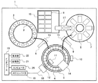
まずは、本発明が適用される自動分析装置の1例について、図1を例に説明する。図1は、自動分析装置の主要部分の上面レイアウトに制御系の概念図を追記した図である。本発明が対象とする自動分析装置は、試料、試薬等の液体を分注ノズルを用いて、所定量採取する機構を備えたものである。以下では、血液、尿等の生体試料の分析を行う、臨床検査用自動分析装置を例にとって説明するが、たとえば、試料ラックを用いて分析部まで搬入するラック方式や、試薬容器の移動におけるロボットハンドリング方式など、本発明はこれに限定されるものではない。 First, an example of an automatic analyzer to which the present invention is applied will be described with reference to FIG. FIG. 1 is a diagram in which a conceptual diagram of a control system is added to the top layout of the main part of the automatic analyzer. An automatic analyzer to which the present invention is directed includes a mechanism for collecting a predetermined amount of a liquid such as a sample or a reagent using a dispensing nozzle. In the following, an explanation will be given by taking as an example an automatic analyzer for clinical examination that analyzes biological samples such as blood and urine. For example, a rack system that carries in to an analysis unit using a sample rack, or a robot for moving reagent containers The present invention is not limited to this, such as a handling method.
自動分析装置1は、試料ディスク2と、その同心円状に配置された試料容器3、反応ディスク4、同心円状に配置された反応容器5、試料分注機構6、第1試薬ディスク7と同心円状に配置された種々の試薬が入った試薬容器8、試薬分注機構9、撹拌機構10、光源11、光度計(多波長光度計)12、A/Dコンバータ13、反応容器洗浄機構14、分注ノズル洗浄機構15、第2試薬保管庫16、試薬容器搬送機構17を備える。
The
自動分析装置1による分析は、以下の順に従い実施される。まず、試料分注機構6が、被分析試料を試料容器3から反応容器5へと分注する。次に、試薬分注機構9が、分析に使用する試薬を試薬容器8から反応容器5へと分注する。続いて、撹拌機構10による混合液の撹拌を行う。光源11から発生し、混合液の入った反応容器5を透過した光は、光度計(多波長光度計)12により検知・測定され、A/Dコンバータ13を介してインタフェース19に送信される。コンピュータ20は、制御部としての機能を有しており、制御部による演算の結果、得られた結果は、記憶手段21に保存されるとともに、情報機器に出力され、たとえば、表示部22に表示される。第1試薬ディスク7内の試薬容器が設置されていない位置には、必要に応じて第2試薬保管庫16より、新しい試薬容器8を試薬容器搬送機構17によって設置される。また、必要がない時や、その試薬容器8を廃棄するときは、試薬容器搬送機構17によって第2試薬保管庫へ当該試薬容器を移設する。分注ノズル洗浄機構15は、試料分注機構6、および試薬分注機構9が、試料、または試薬の分注を行うごとに、分注ノズルの先端を洗浄する。また、反応後の反応容器5は反応容器洗浄機構14によって洗浄され、次の反応に繰り返し使用される。これら分析装置の動作機構は、すべて通信手段18、インタフェース19と介してコンピュータ20に含まれる制御部によって制御される。なお、光度計吸光度に限らず、散乱光度などの反応容器に照射した光を検知する光度計であればよい。
The analysis by the
図2、図3を用いて、上述、第1試薬ディスクから第2試薬保管庫への試薬の移動のタイミングの詳細を説明する。 The details of the timing of reagent movement from the first reagent disk to the second reagent storage will be described with reference to FIGS.
図2、3においては、図1に示した自動分析装置上に2つの試薬ディスクを用いた場合の運用を例に取り説明する。なお、第1試薬ディスク、第2試薬保管庫は、必ずしも同一の一分析装置上になくともよく、1つのシステムに別々のモジュールで構成されるように配置しても良い。また、本実施の形態では、試薬容器の認識にはRFIDを使用しているが、これに限られず、認識方法はバーコードやICチップなど別の手段でも可能である。 2 and 3, the operation when two reagent disks are used on the automatic analyzer shown in FIG. 1 will be described as an example. It should be noted that the first reagent disk and the second reagent storage are not necessarily on the same analyzer, and may be arranged so as to be constituted by separate modules in one system. In this embodiment, the RFID is used for recognizing the reagent container. However, the present invention is not limited to this, and the recognizing method may be another means such as a barcode or an IC chip.
図2は試薬容器の自動交換に際するフローを示した図である。 FIG. 2 is a diagram showing a flow for automatic replacement of reagent containers.
装置にはあらかじめ、全項目、または項目ごとに使用中の試薬容器の残量がどれくらいになったときに、装置が試薬交換のタイミングと認識するかを設定する(ステップS1)。このとき、残量とは体積でも残テスト数、架設後の日数、有効期限でも構わない。また、登録の仕方はオペレータが装置、または装置以外の情報システムの画面上に入力しても、試薬容器そのものにあらかじめ付随しているID(たとえばRFIDやバーコード)を読み込んで設定しても構わない。 In the apparatus, it is set in advance how much the remaining amount of reagent containers in use for all items or items is recognized by the apparatus as a reagent replacement timing (step S1). At this time, the remaining amount may be the volume, the number of remaining tests, the number of days after installation, or the expiration date. In addition, the registration method may be set by reading an ID (for example, RFID or barcode) attached in advance to the reagent container itself, even if the operator inputs it on the screen of the apparatus or an information system other than the apparatus. Absent.
装置の分析中(ステップS2)に試薬残量が設定値以下となった場合、つまり装置が試薬残量が設定値以下と認識した場合(ステップS3)、装置は新しい試薬容器を第2試薬保管庫から第1試薬ディスクへ試薬容器を補充するために、あらかじめ必要な時間分、項目分析を停止する(ステップS4)。その空きサイクルから、一定時間後に発生する最終試薬分注タイミングの空きサイクル(試薬吸引の休止サイクル)時に合わせて、再度試料や第1試薬の分注を止め、試料、試薬の分注がない空きサイクルの間に試薬の搬入や、試薬量の確認などを行う(ステップS5)。そして、試薬交換の実施後に分析を再開する(ステップS6)。 If the reagent remaining amount is less than or equal to the set value during analysis of the device (step S2), that is, if the device recognizes that the reagent remaining amount is less than or equal to the set value (step S3), the device stores a new reagent container in the second reagent storage. In order to replenish the reagent container from the storage to the first reagent disk, the item analysis is stopped for a necessary time in advance (step S4). In accordance with the empty cycle of the final reagent dispensing timing that occurs after a certain time from the empty cycle (pause cycle of reagent aspiration), the dispensing of the sample and the first reagent is stopped again, and the sample and reagent are not dispensed again. During the cycle, the reagent is carried in and the amount of the reagent is confirmed (step S5). Then, the analysis is resumed after the reagent replacement is performed (step S6).
図2における分析を一時的に停止とは、空きサイクル分の時間に相当し、分析が行われない空の反応容器が発生するため、ここでは分析を一時的に停止すると表現している。但し、既に反応容器に試料吐出が行われたものに対しては、この一時停止期間中であっても分析は継続している。 The temporary stop of the analysis in FIG. 2 corresponds to a time corresponding to an empty cycle, and an empty reaction container in which the analysis is not performed is generated. Therefore, it is expressed here that the analysis is temporarily stopped. However, the analysis has been continued for the sample already discharged into the reaction container even during the temporary suspension period.
この試薬容器補充に必要なサイクルは、装置によって異なる。さらには試薬量の確認、試薬容器蓋の開閉、試薬容器の穴あけなどは、最終試薬分注の空きサイクル発生までに行っても、試薬容器補充に必要なサイクルに含んでも構わない。試料吐出後に試薬を吐出する場合には、試料吐出を行わない空きの反応容器を発生させたことによって、試薬の吐出を行う必要のないサイクルが発生する。つまり、試薬分注機構が試薬ディスクの試薬容器から試薬を吸引する必要のないサイクル(無動作時間)が発生する。このタイミングで試薬容器交換(搬入)を実施する。試薬容器を装置に搬入後、必要なチェックを行い、アラーム等の発生がなければ継続して搬入後の試薬容器の試薬を用いた分析が再開される。 The cycle required for refilling the reagent container varies depending on the apparatus. Furthermore, confirmation of the reagent amount, opening / closing of the reagent container lid, drilling of the reagent container, etc. may be performed before the empty cycle of the final reagent dispensing occurs or included in a cycle necessary for reagent container replenishment. When the reagent is discharged after the sample is discharged, an empty reaction container in which the sample is not discharged is generated, thereby generating a cycle in which the reagent does not need to be discharged. That is, a cycle (non-operation time) in which the reagent dispensing mechanism does not need to aspirate the reagent from the reagent container of the reagent disk occurs. At this timing, reagent container replacement (carrying in) is performed. After loading the reagent container into the apparatus, necessary checks are performed. If no alarm is generated, the analysis using the reagent in the reagent container after loading is resumed.
図3は試薬容器搬入スケジュールを入れた動作例を示す。 FIG. 3 shows an operation example in which a reagent container carry-in schedule is entered.
この図3において想定している装置は、項目A,Bの使用する試薬として第1試薬(R1)を吐出する分注機構と第2試薬(R2)を吐出する分注機構とが存在し、試料分注(S)の直後のサイクル(すなわち、試料分注してから1サイクル後)で第1試薬を分注し、試料分注後6サイクル後に第2試薬を分注する2試薬系の測定法を適用した装置である。また、より簡易に説明するため、測定項目は、1容器あたり100テスト分の試薬が充填された項目A,Bの2項目のみを交互で測定し、A項目の残テスト数が5(図中X)以下になった場合に試薬容器の搬入スケジュールが組まれ、その後A項目の試薬容器が装置に搬入されるまで、5サイクル(図中Y)ごとに試料分注を止める設定を想定している。このYは、項目Aの残テスト数が0(ゼロ)になるまで、あとどれくらいかかるかわからない場合に、項目Aの残テスト数が0になった直後にすぐ試薬容器を搬入できるように、第2試薬の空きサイクルを定期的に作るための設定である。この設定は、測定頻度の少ない項目の場合、特に有効になる。第1試薬ディスク内に空きのポジションがあることを前提としているため、使い切った試薬容器の自動搬出については行わない状況である。 The apparatus assumed in FIG. 3 includes a dispensing mechanism for discharging the first reagent (R1) and a dispensing mechanism for discharging the second reagent (R2) as the reagents used in items A and B. A two-reagent system in which the first reagent is dispensed in the cycle immediately after sample dispensing (S) (that is, one cycle after sample dispensing), and the second reagent is dispensed six cycles after sample dispensing. It is a device to which the measurement method is applied. In addition, for the sake of simpler explanation, only two items, items A and B, filled with 100 test reagents per container are measured alternately, and the number of remaining tests for item A is 5 (in the figure). X) Assuming a setting to stop sample dispensing every 5 cycles (Y in the figure) until a reagent container carry-in schedule is made when Yes. This Y is set so that the reagent container can be loaded immediately after the remaining number of tests in item A reaches 0 when it is not known how long it will take until the remaining number of tests in item A reaches 0 (zero). This is a setting for periodically creating two reagent free cycles. This setting is particularly effective for items with a low measurement frequency. Since it is assumed that there is an empty position in the first reagent disk, automatic removal of the used reagent container is not performed.
A項目において、分析中に残テスト数が5以下になった場合(図3、項目割り付け順番5)、予め設定した空きサイクル挿入間隔(Y)ごとに空きサイクルを発生させる。この空きサイクルに伴い、一定時間後に第2試薬の分注に空きサイクル(休止サイクル)が生じる。A項目の残量が0や指定した残テスト数になった場合、この第2試薬の空きサイクルと同じサイクルで試料分注、第1試薬分注を止め、試薬ディスクに両方の分注ノズルが試薬を吸引しない、サイクル(休止サイクル)を発生させ、その間に試薬容器の搬入を行う。また、試薬容器搬入後に、たとえば第1試薬分注ノズルを使用して、第1試薬、第2試薬の試薬量のチェックなどを行う。 In the item A, when the number of remaining tests becomes 5 or less during analysis (FIG. 3, item allocation order 5), an empty cycle is generated at every preset empty cycle insertion interval (Y). Along with this empty cycle, an empty cycle (pause cycle) occurs in dispensing the second reagent after a certain time. When the remaining amount of item A reaches 0 or the specified number of remaining tests, sample dispensing and first reagent dispensing are stopped in the same cycle as the second reagent empty cycle, and both dispensing nozzles are placed on the reagent disk. A cycle in which the reagent is not aspirated (rest cycle) is generated, and the reagent container is carried in during that cycle. In addition, after the reagent container is carried in, for example, the first reagent dispensing nozzle is used to check the reagent amounts of the first reagent and the second reagent.
次に、図3をより一般化した制御フローを図4、5を用いて説明する。なお、項目Aの残量を監視する例について説明する。 Next, a generalized control flow of FIG. 3 will be described with reference to FIGS. An example of monitoring the remaining amount of item A will be described.
制御部は、スタートによって、分析を開始する(ステップS400)。つまり、試料と測定依頼項目に対応する試薬を同じ反応容器に吐出して、光度計による吸光度や散乱光度を測定する。続いて、制御部は、次の分析があるかどうかを判定する(ステップS401)。ステップS401で判定した結果がNOである場合(すなわち、次の分析がない場合)には分析を終了し、既に反応容器に吐出した試料の分析結果を待って、結果を出力する。一方、ステップS401での判定結果がYESである場合には、ステップS400と同様に吸光度等を測定する(ステップS402)。次に、制御部は、項目Aの残量が閾値以下かどうかを判定する(ステップS403)。ステップS403での判定結果がNOである場合(すなわち、閾値より大きい場合)には、ステップS401に戻る。一方、ステップS403での判定結果がYESである場合(すなわち、閾値以下となった場合)には、空きサイクルを発生させるモードに移行する(モード移行)。なお、試薬の残量については、制御部によって管理されているため項目Aの残量は容易に把握できる。 The control unit starts analysis by starting (step S400). That is, the sample and the reagent corresponding to the measurement request item are discharged into the same reaction container, and the absorbance and scattered light intensity are measured by the photometer. Subsequently, the control unit determines whether there is a next analysis (step S401). If the result determined in step S401 is NO (that is, if there is no next analysis), the analysis is terminated, the analysis result of the sample already discharged into the reaction container is waited, and the result is output. On the other hand, if the determination result in step S401 is YES, the absorbance or the like is measured in the same manner as in step S400 (step S402). Next, the control unit determines whether or not the remaining amount of item A is equal to or less than a threshold value (step S403). If the determination result in step S403 is NO (ie, greater than the threshold value), the process returns to step S401. On the other hand, when the determination result in step S403 is YES (that is, when the determination result is equal to or less than the threshold value), the mode shifts to a mode in which an empty cycle is generated (mode shift). Since the remaining amount of the reagent is managed by the control unit, the remaining amount of the item A can be easily grasped.
次に、モード移行した場合について説明する。ステップS403での判定結果がYESである場合(すなわち、モード移行した場合)でも、ステップS401とS402と同様のフローを経由する(ステップS404とS405)。次に、制御部は、項目Aの残量が0(ゼロ)か否かを判定する(ステップS406)。ステップS406での判定結果がYESである場合(すなわち、項目Aの残量が0の場合)には、試薬搬入準備が開始されるが、この点については後述する。一方、ステップS406での判定結果がNOの場合(すなわち、0でない場合)には、制御部は、次でステップS403からaサイクル経過するかどうかを判定する(ステップS407)。なお、ここでのaサイクルは、図3のYに相当する。ステップS407での判定結果がNOである場合(すなわち、経過しない場合)には、ステップS404に戻る。また、ステップS407での判定結果がYESである場合(すなわち、経過する場合)には、空きサイクルを発生させる(ステップS408)。空きサイクルとは、分析対象試料があっても意図的に反応容器に試料を吐出しないサイクルのことである。このステップS404〜S408の一連のフローによって、aサイクルに1回空きサイクルが発生することになる。なお、ステップS406においては、項目Aの残量が0であるか否かを判定したが、その閾値は0(ゼロ)でなくてもよく、ステップS403の閾値より小さい閾値をステップS406の判定基準としてもよい。また、aサイクルに連続して複数の空きサイクルを発生させてもよいが、処理能力の低下を防ぐため1サイクルが望ましい。 Next, the case where the mode is changed will be described. Even when the determination result in step S403 is YES (that is, when the mode is changed), the same flow as in steps S401 and S402 is performed (steps S404 and S405). Next, the control unit determines whether the remaining amount of item A is 0 (zero) (step S406). When the determination result in step S406 is YES (that is, when the remaining amount of the item A is 0), the reagent carry-in preparation is started, which will be described later. On the other hand, when the determination result in step S406 is NO (that is, not 0), the control unit determines whether or not a cycle elapses from step S403 next (step S407). Here, the a cycle corresponds to Y in FIG. If the determination result in step S407 is NO (that is, if it has not elapsed), the process returns to step S404. If the determination result in step S407 is YES (that is, if it has elapsed), an empty cycle is generated (step S408). An empty cycle is a cycle in which a sample is not intentionally discharged into a reaction vessel even when there is a sample to be analyzed. With the series of steps S404 to S408, an empty cycle occurs once per a cycle. In step S406, it is determined whether or not the remaining amount of item A is 0. However, the threshold value may not be 0 (zero), and a threshold value smaller than the threshold value in step S403 is set as the determination criterion in step S406. It is good. In addition, a plurality of idle cycles may be generated continuously with the a cycle, but one cycle is desirable to prevent a decrease in processing capacity.
次に、空きサイクルを発生された後のフローについて説明する。ステップS408の処理により空きサイクルを発生させた場合でも、ステップS404〜S406と同様のフローを経由する(ステップS409〜S411)。次に、制御部は、次でステップS408からbサイクル経過するかどうかを判定する(ステップS412)。なお、ここでのbサイクルも、図3のYに相当する。ステップS412での判定結果がNOである場合(すなわち、経過しない場合)には、ステップS409に戻る。また、ステップS412での判定結果がYESである場合(すなわち、経過する場合)には、ステップS408に戻り、空きサイクルを発生させる(ステップS408)。このステップS409〜S401に加え、ステップS408の一連のフローによって、項目Aの残量が0になるまで、bサイクルに1回空きサイクルが発生することになる。 Next, the flow after the empty cycle is generated will be described. Even when an empty cycle is generated by the processing in step S408, the same flow as in steps S404 to S406 is performed (steps S409 to S411). Next, the control unit determines whether b cycles have elapsed from step S408 (step S412). The b cycle here also corresponds to Y in FIG. If the determination result in step S412 is NO (that is, if it has not elapsed), the process returns to step S409. If the determination result in step S412 is YES (that is, if it has elapsed), the process returns to step S408 to generate an empty cycle (step S408). In addition to steps S409 to S401, the series of flows in step S408 causes a free cycle to occur once in b cycles until the remaining amount of item A becomes zero.
なお、aサイクルとbサイクルとで分けた理由は、図3では、同じサイクル数で説明したが、必ずしも同じである必要はなく、最初に空きサイクルを発生させるタイミングであるaは任意であるためである。一方、bサイクルは装置機構に異存している。第1試薬を吐出する分注機構と第2試薬を吐出する分注機構とが存在しており、第2試薬を吐出するタイミングは、第1試薬を吐出するタイミングから決まったサイクル数経過した後であるためである。このため、このサイクル数と同じか、このサイクル数の約数をbとして設定することで、第1試薬と第2試薬との双方を吐出しないサイクル(休止サイクル)を定期的に発生させることができる。残量が、0でなくてもよく、ステップS403の閾値より小さい閾値をステップS411の判定基準としてもよいことは、前述と同様であり、また、bサイクルに連続して複数の空きサイクルを発生させてもよいが、処理能力の低下を防ぐため1サイクルが望ましい。 The reason for dividing the a cycle from the b cycle has been described with reference to the same number of cycles in FIG. 3, but it is not necessarily the same, and a is a timing at which a free cycle is first generated is arbitrary. It is. On the other hand, the b cycle is different from the device mechanism. There are a dispensing mechanism for discharging the first reagent and a dispensing mechanism for discharging the second reagent, and the timing of discharging the second reagent is after a predetermined number of cycles have elapsed from the timing of discharging the first reagent. This is because. For this reason, a cycle (pause cycle) in which both the first reagent and the second reagent are not discharged can be periodically generated by setting b to be the same as the number of cycles or a divisor of the number of cycles. it can. The remaining amount may not be 0, and a threshold value smaller than the threshold value in step S403 may be used as the determination criterion in step S411, as described above, and a plurality of empty cycles are generated continuously after b cycles. However, one cycle is desirable to prevent a decrease in processing capacity.
次に、ステップS406,S411での判定結果がYESである場合、すなわち、項目Aの残量が0になった後のフローについて図5を用いて説明する。ステップS406,S411での判定結果がYESである場合(項目Aの残量が0になった場合)、制御部は、試薬搬入準備を開始を試薬容器搬入機構に指示する(ステップS413)。ここで、試薬搬入準備とは、試薬容器搬入機構が項目Aに対応する試薬と同じ種類の試薬が収容された試薬容器を把持し、把持した試薬容器を試薬ディスク近傍まで搬送する準備動作を意味する。試薬容器搬入機構の性能に依存するが、この準備動作には、3サイクル〜6サイクル程度の時間を要する。また、ステップS413の処理(試薬投入準備開始)を指示した後、ステップS401とS402と同様のフローを経由する(ステップS414〜S415)。次に、制御部は、試薬搬入準備が完了しているかどうか及び、次のサイクルが、第1試薬と第2試薬との双方を吐出しない試薬吐出休止サイクルであるかどうかを判定し(ステップS416)、判定結果がYESである場合には、試薬ディスク近傍で待機している試薬容器を、試薬ディスクの空きポジションに搬入する(ステップS419)。つまり、試薬搬入準備が完了した後の直近の試薬吐出休止サイクルで試薬容器を搬入する。この搬入については、1サイクルで搬入を完了させることができる。一方、ステップS416での判定結果がNOの場合(すなわち、搬入準備が完了していない場合、又は、次のサイクルが試薬吐出休止サイクルでない場合)には、制御部は、ステップS412と同様の判定を行い、空きサイクルを発生させるか否かを制御する(ステップS417、S418)。すなわち、ステップS416での判定結果がYESの場合には、空きサイクルを発生させ(ステップS418)、ステップS414に戻る。また、ステップS416での判定結果がNOの場合には、ステップS414に戻る。このようなフローにより、S416の条件を満たすまで、bサイクルに1回、定期的に空きサイクルを発生させ、定期的に試薬吐出休止サイクルを発生し続ける。試薬容器の搬入が完了した場合には、試薬量のチェックを行った後(ステップS420)、ステップS401に戻って、分析を継続する。 Next, the flow after the determination result in steps S406 and S411 is YES, that is, the flow after the remaining amount of the item A becomes 0 will be described with reference to FIG. When the determination result in steps S406 and S411 is YES (when the remaining amount of item A becomes 0), the control unit instructs the reagent container carry-in mechanism to start the reagent carry-in preparation (step S413). Here, the preparation for carrying in the reagent means a preparatory operation in which the reagent container carrying mechanism grips the reagent container containing the same type of reagent as the reagent corresponding to item A and transports the gripped reagent container to the vicinity of the reagent disk. To do. Although depending on the performance of the reagent container carry-in mechanism, this preparatory operation requires a time of about 3 to 6 cycles. In addition, after instructing the processing of step S413 (reagent introduction start), the same flow as in steps S401 and S402 is performed (steps S414 to S415). Next, the control unit determines whether or not the reagent carry-in preparation is completed and whether or not the next cycle is a reagent discharge pause cycle in which neither the first reagent nor the second reagent is discharged (step S416). If the determination result is YES, the reagent container waiting in the vicinity of the reagent disk is carried into the empty position of the reagent disk (step S419). That is, the reagent container is carried in the latest reagent discharge pause cycle after the reagent carry-in preparation is completed. About this carrying-in, carrying-in can be completed in 1 cycle. On the other hand, when the determination result in step S416 is NO (that is, when the carry-in preparation is not completed, or when the next cycle is not the reagent discharge suspension cycle), the control unit performs the same determination as in step S412. To control whether or not to generate an empty cycle (steps S417 and S418). That is, if the determination result in step S416 is YES, an empty cycle is generated (step S418), and the process returns to step S414. If the determination result at step S416 is NO, the process returns to step S414. By such a flow, until the condition of S416 is satisfied, an empty cycle is periodically generated once in b cycle, and a reagent discharge pause cycle is continuously generated periodically. When the loading of the reagent container is completed, after checking the reagent amount (step S420), the process returns to step S401 to continue the analysis.
次に、試薬量のチェックについて説明する。試薬量のチェックは、十分試薬量がある試薬容器を搬入できたか否かを判定する動作である。例えば、試薬分注ノズルを所定量試薬容器内に下降させて、吸引動作を行い、所定量の試薬が入っているかを吸引動作時の圧力を監視することでチェックする。試薬量が十分ない場合には、正常な分析結果が得られないなどの様々な問題が発生するため、必ず行う必要がある。項目Aの分析遅滞を無くすために、試薬容器を搬入した後、できるだけ早くこのチェックを行うことが望ましい。このため、図3では、試薬容器搬入の16サイクル直後の17と18サイクルで、このチェックを行っている。また、図3では、第1試薬用の容器と第2試薬用の容器とが一体となった試薬容器を試薬ディスクに搬入した例であるため、両容器に対してチェックを行っている。通常、第2試薬用の容器の第2試薬に対して、第1試薬用の分注機構を用いることはないが、できるだけ早くチェックを行うために、第1試薬の試薬量のチェックのみならず、第2試薬の試薬量のチェックを、第1試薬を吐出する分注機構で、行うことが望ましい。 Next, the reagent amount check will be described. The reagent amount check is an operation for determining whether or not a reagent container having a sufficient reagent amount has been carried in. For example, the reagent dispensing nozzle is lowered into a predetermined amount of the reagent container, a suction operation is performed, and whether a predetermined amount of reagent is contained is checked by monitoring the pressure during the suction operation. If the amount of reagent is not sufficient, various problems such as failure to obtain a normal analysis result occur. In order to eliminate the analysis delay of item A, it is desirable to perform this check as soon as possible after loading the reagent container. For this reason, in FIG. 3, this check is performed in 17 and 18 cycles immediately after 16 cycles of carrying in the reagent container. FIG. 3 shows an example in which a reagent container in which a container for a first reagent and a container for a second reagent are integrated is loaded into a reagent disk, so that both containers are checked. Normally, the dispensing mechanism for the first reagent is not used for the second reagent in the container for the second reagent. However, in order to check as soon as possible, not only the reagent amount of the first reagent is checked. It is desirable to check the reagent amount of the second reagent with a dispensing mechanism that discharges the first reagent.
仮に、第2試薬の試薬量のチェックを、第2試薬を吐出する分注機構で行おうとする場合には、試薬量のチェックのために1サイクル使うため、試料を吐出しない空きサイクルを発生させる必要があるが、この空きサイクルを発生させたとしても、この空きサイクルが第2試薬の吐出位置に到達するには、相当のサイクル数を要するため、チェックの迅速性に欠け、処理能力の低下を招く虞がある。なお、空きサイクルが第2試薬の吐出位置に到達する前は、既に反応容器に吐出した試料に対し、第2試薬を吐出しなくてはならず、このチェックを行うことはできない。一方、これを第1試薬を吐出する分注機構で行う場合には、空きサイクルを発生させた次のサイクルで、試料が収容されていない空の反応容器が、第1試薬の吐出位置に到達するため、空きサイクルを発生させた直後に第2試薬用の容器をチェックすることができる。チェック迅速化のために、第1試薬用の容器と第2試薬用の容器に対し、連続してチェックを行うためには、図3で示すように、試薬搬入のサイクルと、この次のサイクルを、試料を吐出しない空きサイクルとして発生させておくことが望ましい。 If the reagent amount of the second reagent is to be checked by a dispensing mechanism that discharges the second reagent, one cycle is used to check the reagent amount, so that an empty cycle that does not discharge the sample is generated. Although it is necessary, even if this empty cycle is generated, it takes a considerable number of cycles for this empty cycle to reach the second reagent discharge position. There is a risk of inviting. Note that before the empty cycle reaches the discharge position of the second reagent, the second reagent must be discharged to the sample that has already been discharged to the reaction container, and this check cannot be performed. On the other hand, when this is performed by a dispensing mechanism that discharges the first reagent, an empty reaction container that does not contain a sample reaches the discharge position of the first reagent in the next cycle after generating the empty cycle. Therefore, the container for the second reagent can be checked immediately after the empty cycle is generated. In order to perform the check continuously for the first reagent container and the second reagent container in order to speed up the check, as shown in FIG. 3, the reagent carry-in cycle and the next cycle Is preferably generated as an empty cycle in which the sample is not discharged.
以上、本発明に係る、所定の項目に対する試薬の残量が閾値以下となった場合に、試薬分注機構が試薬ディスクの試薬容器内から試薬を吸引しない試薬吸引の休止サイクルを定期的に発生させ、休止サイクルで試薬容器搬送機構によって、所定の項目に対する試薬と同じ種類の試薬が収容された試薬容器を自動で試薬ディスクに搬入する、制御部による制御を説明した。図4、5の例によれば、bサイクルに1回空きサイクルを発生させることで、1サイクルの試薬吸引の休止サイクルを定期的に発生させることができる。そして、この休止サイクルで、試薬容器搬送機構で自動で試薬容器を搬入することができる。bサイクルに1回空きサイクルが入るため、このモードに移行した後、残量0又は所定の残量の試薬容器搬入準備のトリガがかかるまで、期間処理能力が低下するが、定期的に休止サイクルを発生させているので、このトリガがかかった時点から短時間で試薬容器を搬入することができる。また、試薬の使用頻度によって、モード移行の閾値や、このbの値を設定すれば、処理能力の低下を最小限に抑えることができる。加えて、試薬容器搬送機構で自動で搬入するため、搬入にかかる時間も短時間で、かつ、ユーザが試薬搬入に立ち会う必要がなく、分析が継続できる。説明の便宜上、図3では、第1試薬の吐出と第2試薬の吐出のタイミングが、5サイクル離れた例で説明したが、装置によっては、このタイミングが30サイクル以上離れており、特にこのサイクル数が離れていれば離れている程、搬入にかかる時間が短くなる効果は大きくなる。
As described above, the reagent dispensing mechanism periodically generates a reagent aspiration pause cycle in which the reagent is not aspirated from the reagent container of the reagent disk when the remaining amount of the reagent for the predetermined item is equal to or less than the threshold value according to the present invention. The control by the control unit has been described in which the reagent container in which the reagent of the same type as the reagent for the predetermined item is automatically loaded into the reagent disk by the reagent container transport mechanism in the pause cycle. According to the examples of FIGS. 4 and 5, the idle cycle of one cycle can be periodically generated by generating the empty cycle once in the b cycle. In this pause cycle, the reagent container can be automatically loaded by the reagent container transport mechanism. Since there is one empty cycle in the b cycle, the period processing capacity decreases after the transition to this mode until a trigger for preparation of loading the remaining amount of the reagent container with the remaining
また、図4では、ステップS406やS411の判定基準を設ける例を説明したが、変形例として、これらの判定基準を設けずに、ステップS403の判定に基づき、試薬搬入準備(ステップS413)を行うこともできる。しかし、休止サイクルを発生させるのにある程度の時間を要するため、真に試薬の搬入が必要な条件である閾値(ステップS406、S411)よりも、大きい閾値を処理能力低下モードの移行の閾値と設定しておくことが望ましい。つまり、ステップS404の閾値より小さい閾値又は0になるまで、休止サイクルを定期的に発生させ、その後に、試薬容器を搬入することが望ましい。これにより、真に試薬の搬入が必要な条件を満たしたときに、迅速に試薬の搬入を行うことができる。 In FIG. 4, the example in which the determination criteria of steps S406 and S411 are provided has been described. However, as a modification, the reagent preparation for preparation (step S413) is performed based on the determination of step S403 without providing these determination criteria. You can also. However, since a certain amount of time is required to generate the pause cycle, a threshold value that is larger than the threshold value (steps S406 and S411) that is a condition that truly requires the loading of the reagent is set as the threshold value for shifting to the processing capacity reduction mode. It is desirable to keep it. That is, it is desirable to periodically generate a pause cycle until the threshold value is smaller than the threshold value in Step S404 or 0, and then carry in the reagent container. This makes it possible to quickly carry in the reagent when conditions that truly require the reagent to be carried are satisfied.
また、休止サイクルが発生する頻度(例えば、bサイクルに1回)は、試薬容器搬送機構が試薬保管庫から試薬ディスクまで試薬容器を搬送するサイクル数よりも長く設定されていることが望ましい。休止サイクルの発生頻度は、試料を吐出しない空きサイクルの発生頻度を同じであり、試薬容器を搬送している間に、分析能力の低下の原因となる空きサイクルの発生を抑制することができるためである。 Further, it is desirable that the frequency at which the pause cycle occurs (for example, once every b cycle) is set longer than the number of cycles in which the reagent container transport mechanism transports the reagent container from the reagent storage to the reagent disk. The frequency of the idle cycle is the same as the frequency of the empty cycle that does not discharge the sample, and it is possible to suppress the occurrence of an empty cycle that causes a decrease in the analytical capability while the reagent container is being transported. It is.
また、図4、5では項目Aに着目したが、項目Bについても同様のフローで試薬容器の搬入することができる。但し、使用頻度によって、処理能力の低下期間を短くするため、閾値と休止サイクルの発生頻度は、試薬の種類に応じて設定可能な表示画面を備えることが好ましい。 4 and 5, the item A is focused on, but the reagent container can be carried in the item B in the same flow. However, in order to shorten the degradation period of the processing capacity depending on the use frequency, it is preferable to provide a display screen in which the threshold value and the occurrence frequency of the pause cycle can be set according to the type of reagent.
また、2以上の異なる試薬を考慮すると、夫々の試薬残量が閾値以下になることで処理能力が低下するモードに移行する場合がある。このような場合に、図4、5の例に習えば、数サイクル中に2回休止サイクルが発生することになるため、必要以上に処理能力が低下する虞がある。この場合には、一方の休止サイクルを発生させずに、他方の休止サイクルを発生させることが望ましい。また、同様に、仮に設定された発生頻度が同じ場合には、図4、5の例に習えば、数サイクル中に2回休止サイクルが発生することになる虞がある。この場合には、同じサイクルで休止サイクルが生じるように、ステップS407のaを制御部で調整し、制御することが望ましい。 In addition, when two or more different reagents are taken into account, the mode may shift to a mode in which the processing capacity is lowered when the remaining amount of each reagent falls below a threshold value. In such a case, if the example of FIGS. 4 and 5 is learned, a pause cycle will occur twice in several cycles, so there is a possibility that the processing capacity will be lowered more than necessary. In this case, it is desirable to generate the other pause cycle without generating one pause cycle. Similarly, if the set occurrence frequency is the same, there is a possibility that two pause cycles will occur in several cycles if the examples shown in FIGS. In this case, it is desirable to adjust and control a in step S407 by the control unit so that a pause cycle occurs in the same cycle.
なお、実施形態では、主に試薬ディスクへの搬入について説明したが、試薬容器を搬入する空きポジションがない場合など試薬ディスクからの試薬容器の搬出しなければならない場合についても、この休止サイクルを用いて、試薬容器搬送機構で自動で行うことができる。この場合は、休止サイクルで試薬容器を搬出して、別の休止サイクルで試薬容器を搬入することができる。また、実施形態では、第1試薬を試料の後に吐出する形態について説明したが、試薬吸引を休止する休止サイクルを設け、このタイミングで試薬容器を搬入する制御を行うのであれば、第1試薬を試料の前に吐出する形態についても、同様に適用できる。 In the embodiment, the introduction to the reagent disk has been mainly described. However, this pause cycle is also used when the reagent container has to be unloaded from the reagent disk, such as when there is no empty position to carry the reagent container. And can be automatically performed by the reagent container transport mechanism. In this case, it is possible to carry out the reagent container in a pause cycle and carry in the reagent container in another pause cycle. In the embodiment, the first reagent is discharged after the sample. However, if a pause cycle for stopping the reagent aspiration is provided and the control for loading the reagent container is performed at this timing, the first reagent is removed. The same applies to the mode of discharging before the sample.
以上、本願の実施形態について説明した。本発明によると、試薬容器の交換が必要な際に、装置の分析を止めざるを得ない状況において、オペレータの作業なしで装置の分析停止時間を最小限にとどめることで、業務効率の向上が可能になる。 The embodiment of the present application has been described above. According to the present invention, when the reagent container needs to be replaced, it is possible to improve the operational efficiency by minimizing the analysis stop time of the apparatus without the operator's work in a situation where the analysis of the apparatus must be stopped. It becomes possible.
以上のように構成した本実施の形態における効果を説明する。 The effect in this Embodiment comprised as mentioned above is demonstrated.
臨床検査技師など臨床現場での作業者は、医療費削減の流れの中で最小限にとどめられ、一人の技師で複数の業務を担当し、多忙を極めている。そうした多忙な業務の中に、装置のメンテナンスや試薬交換、検量線管理、精度管理なども含まれる。そのため、現状では、実際にオペレータが行わなければならないメンテナンスの数を減らすことが求められている。自動分析装置では、試料の分注後、複数の試薬を一定の時間で分注する必要がある。ほとんどの自動分析装置では、1つ目の試薬が分注され、その約5分後に次の試薬が分注される。この時間は、測定反応において非常に重要な要素であり、正しく分析するために第2試薬分注の時間を変更することはできない。 Workers in clinical settings such as clinical laboratory technicians are kept to a minimum in the flow of reducing medical expenses, and one engineer is in charge of multiple tasks and is extremely busy. Such busy tasks include equipment maintenance, reagent replacement, calibration curve management, and accuracy management. Therefore, at present, it is required to reduce the number of maintenance that the operator must actually perform. In an automatic analyzer, after dispensing a sample, it is necessary to dispense a plurality of reagents in a certain time. In most automatic analyzers, the first reagent is dispensed, and about 5 minutes later, the next reagent is dispensed. This time is a very important factor in the measurement reaction, and the time for dispensing the second reagent cannot be changed for correct analysis.
このような臨床現場において、オペレータによる試薬交換作業低減のため、試薬容器を自動で装置の試薬容器を設置する場所へ設置する機能を有する装置が近年、上市されている。実際に試薬容器を装填する場合、試薬容器を一時的に保管している場所から設置予定場所まで運ぶため、一定の時間が必要である。そのため、試薬容器の補充作業をするためには、試料の分注を止め、現在測定依頼が装置に送られている分析の最後の試薬が吐出されるまでの時間を待たなければならなく、特に検査依頼が大量にある時間帯では、必ずしも有意な機能とは言い切れないのが実態である。特許文献1では、あらかじめ装置に試薬容器の補充する指示を与え、分析するための分注を指定時間止めるとともに、試薬容器の充填が可能になるまでの時間を装置などの画面で表示するための機能について述べている。この発明では、五月雨的に生じる試薬容器の補充作業を、オペレータの意思で行うことにより、装置の本来の処理能力を極力落とさずに、試薬容器の補充を可能にするものである。しかし、オペレータによる作業や確認が発生することや、すでに分析依頼が入っている項目については、必要な試薬分注の全てが完了してからでないと試薬交換が実行できない事から、作業者の負担軽減や、迅速分析までは実現できていなかった。
In such a clinical field, in order to reduce reagent replacement work by an operator, an apparatus having a function of automatically installing a reagent container at a place where the reagent container of the apparatus is installed has been put on the market in recent years. When the reagent container is actually loaded, a certain time is required because the reagent container is transported from the temporary storage location to the planned installation location. Therefore, in order to replenish the reagent container, it is necessary to stop dispensing the sample and wait for the time until the last reagent in the analysis for which the current measurement request is sent to the device is discharged, especially In fact, it is not always a significant function during a time period when there are a large number of inspection requests. In
これに対して、本実施の形態においては、所定の項目に対する試薬の残量が第1閾値以下となった場合に、該試薬分注機構が該試薬ディスクの試薬容器内から試薬を吸引しない試薬吸引の休止サイクルを定期的に発生させ、該休止サイクルで該試薬容器搬送機構によって、該所定の項目に対する試薬と同じ種類の試薬が収容された試薬容器を自動で該試薬ディスクに搬入するように構成したので、使用中の試薬容器内の残量を監視し、任意に設定した残量になった時点で、試薬容器を指定場所へ搬入するのに必要な時間だけ、試料、またはそれに付随する試薬の分注を止め、試薬容器搬入出に際する装置の分析停止時間を最小限にすることができる。 On the other hand, in the present embodiment, the reagent dispensing mechanism does not aspirate the reagent from the reagent container of the reagent disk when the remaining amount of the reagent for the predetermined item is equal to or less than the first threshold value. A suction pause cycle is periodically generated, and in this pause cycle, a reagent container containing the same type of reagent as the reagent for the predetermined item is automatically carried into the reagent disk by the reagent container transport mechanism. Because it is configured, the remaining amount in the reagent container in use is monitored, and when it reaches the arbitrarily set remaining amount, only the time required to carry the reagent container to the specified location is attached to the sample or it The dispensing of the reagent can be stopped, and the analysis stop time of the apparatus when carrying in / out the reagent container can be minimized.
1…分析装置、2…試料ディスク、3…試料容器、4…反応ディスク、5…反応容器、6…試料分注機構、7…第1試薬ディスク、8…試薬容器、9…試薬分注機構、10…攪拌機構、11…光源、12…多波長計、13…A/Dコンバータ、14…反応容器洗浄機構、15…分注ノズル洗浄機構、16…第2試薬保管庫、17…試薬容器搬送機構、18…通信手段、19…インタフェース、20…コンピュータ、21…記憶手段、22…表示部
DESCRIPTION OF
Claims (9)
該反応容器に光を照射する光源と、
該反応容器に照射した光を検知する光度計と、
反応に使用する試薬を収容した試薬容器が設置される試薬ディスクと、
試薬を収容した該試薬容器を保管する試薬保管庫と、
該試薬保管庫から該試薬ディスクの近傍まで該試薬容器を搬送して該試薬ディスクに搬入する試薬容器搬送機構と、
該試薬ディスクに設置された該試薬容器から試薬を吸引し、該反応容器に吐出する試薬分注機構と、
該反応容器に試料を吐出する試料分注機構と、
該試薬分注機構、及び、該試薬容器搬送機構を制御する制御部と、を備え、
1つのサイクルを単位とする複数の連続するサイクルで測定の管理や運用を行う場合において、
該制御部は、該試薬容器が該試薬ディスクに搬入されたときの試薬量に基づいて所定の項目に対する試薬の残量を管理するとともに、該所定の項目に対する試薬の残量が第1閾値以下となった場合に、該試薬分注機構が該試薬ディスクの試薬容器内から試薬を吸引しない試薬吸引の休止サイクルを定期的に発生させ、該休止サイクルで該試薬容器搬送機構によって、該所定の項目に対する試薬と同じ種類の試薬が収容された、試薬保管庫に保管されている試薬容器を自動で該試薬ディスク近傍まで搬送して該試薬ディスクに搬入する制御を行うことを特徴とする自動分析装置。 A reaction disk which the reaction vessel reacting a sample and a reagent Ru is placed,
A light source for irradiating the reaction vessel with light;
A photometer for detecting the light applied to the reaction vessel;
A reagent disk reagent container containing a reagent used for the reaction Ru is installed,
And a storing reagent container said reagent container containing a reagent,
A reagent container transfer mechanism for carrying the reagent disk by conveying the reagent containers from the reagent depot to the vicinity of the reagent disk,
A reagent dispensing mechanism sucks a reagent from the installed the reagent containers to the reagent disk, and discharges to the reaction vessel,
A sample dispensing mechanism for discharging the sample into the reaction vessel;
The reagent dispensing mechanism, and a control unit for controlling the reagent container transport mechanism,
When managing and operating measurements in multiple consecutive cycles with one cycle as the unit,
The control unit manages the remaining amount of reagent for a predetermined item based on the amount of reagent when the reagent container is carried into the reagent disk, and the remaining amount of reagent for the predetermined item is equal to or less than a first threshold value. The reagent dispensing mechanism periodically generates a reagent aspiration pause cycle in which the reagent is not aspirated from within the reagent container of the reagent disk, and the reagent container transport mechanism in the pause cycle causes the predetermined Automatic analysis characterized in that a control is performed to automatically transport a reagent container stored in a reagent storage container containing a reagent of the same type as the reagent for the item to the vicinity of the reagent disk and carry it into the reagent disk. apparatus.
該制御部は、該所定の項目に対する試薬の残量が、該第1閾値より小さい第2閾値又は0になるまで、該休止サイクルを定期的に発生させ、その後に、該試薬容器を自動で該試薬ディスク近傍まで搬送して該試薬ディスクに搬入する制御を行うことを特徴とする自動分析装置。 The automatic analyzer according to claim 1, wherein
The control unit periodically generates the pause cycle until the remaining amount of the reagent for the predetermined item becomes a second threshold value that is smaller than the first threshold value or 0, and then automatically releases the reagent container. An automatic analyzer characterized in that control is performed for transporting to the vicinity of the reagent disk and loading into the reagent disk .
該試薬容器搬送機構は、該試薬容器搬送機構で該試薬保管庫から搬入対象となる試薬容器を把持し、把持した該試薬容器を該試薬ディスク近傍まで搬送する機能と、該試薬ディスク近傍まで搬送された該試薬容器を試薬ディスクに搬入する機能とを有し、
該制御部は、該所定の項目に対する試薬の残量が、該第2閾値又は0になったことを判定し、該試薬容器搬送機構で該試薬保管庫から搬入対象となる試薬容器を把持し、把持した該試薬容器を該試薬ディスク近傍まで搬送する準備動作を行い、当該準備動作が完了した後の直近の該休止サイクルで、該試薬容器を試薬ディスクに搬入する制御を行うことを特徴とする自動分析装置。 The automatic analyzer according to claim 2,
The reagent container transport mechanism grips the reagent container to be loaded from the reagent storage by the reagent container transport mechanism, transports the gripped reagent container to the vicinity of the reagent disk, and transports the reagent container to the vicinity of the reagent disk. A function of carrying the reagent container into a reagent disk,
The control unit determines that the remaining amount of the reagent for the predetermined item has reached the second threshold value or 0, and grips the reagent container to be loaded from the reagent storage by the reagent container transport mechanism. Performing a preparatory operation for transporting the gripped reagent container to the vicinity of the reagent disk, and performing a control for carrying the reagent container into the reagent disk in the immediate rest cycle after the preparatory operation is completed. Automatic analyzer to do.
該休止サイクルが発生する頻度は、該試薬容器搬送機構が該試薬保管庫から該試薬ディスク近傍まで該試薬容器を搬送するサイクル数よりも長く設定されていることを特徴とする自動分析装置。 The automatic analyzer according to claim 3,
Frequency of the pause cycle occurs, an automatic analyzer, characterized in that it is set longer than the number of cycles reagent container transfer mechanism to transport the reagent containers from the reagent depot to the vicinity reagent disk.
該試薬分注機構は、第1試薬分注機構と第2試薬分注機構とを備え、該休止サイクルではすべての試薬分注機構が試薬の吸引を行わないことを特徴とする自動分析装置。 The automatic analyzer according to claim 1, wherein
The reagent dispensing mechanism includes a first reagent dispensing mechanism and a second reagent dispensing mechanism, and all the reagent dispensing mechanisms do not perform reagent aspiration in the pause cycle.
該第1試薬分注機構は、第1試薬を吐出する分注機構で、
該第2試薬分注機構は、第2試薬を吐出する分注機構で、
搬入される該試薬容器は第1試薬用の容器と第2試薬用の容器とが一体となった試薬容器であり、
該制御部は、該試薬容器が自動で該試薬ディスクに搬入された後、該第1試薬分注機構によって、第1試薬と第2試薬の試薬量のチェックを行う制御を行うことを特徴とする自動分析装置。 The automatic analyzer according to claim 5, wherein
The first reagent dispensing mechanism is a dispensing mechanism that discharges the first reagent,
The second reagent dispensing mechanism is a dispensing mechanism that discharges the second reagent,
The reagent container to be carried in is a reagent container in which a container for a first reagent and a container for a second reagent are integrated.
The control unit performs control to check the reagent amounts of the first reagent and the second reagent by the first reagent dispensing mechanism after the reagent container is automatically loaded into the reagent disk . Automatic analyzer to do.
該第1閾値と該休止サイクルの発生頻度を、試薬の種類に応じて設定可能な表示画面を備えることを特徴とする自動分析装置。 The automatic analyzer according to claim 1, wherein
The frequency of said first threshold and said rest cycle, an automatic analyzer, characterized in that it comprises a configurable display screen according to the kind of the reagent.
該制御部は、該所定の項目に対する試薬の残量がその試薬に対する該第1閾値として設定された第3閾値以下、かつ、該所定の項目に対する試薬と種類が異なる試薬の残量がその試薬に対する第1閾値として設定された第4閾値以下である場合であって、両試薬に対して該表示画面で設定された休止サイクルの発生頻度が異なる場合に、前記両試薬に対する該休止サイクルのうち一方の試薬に対する休止サイクルを発生させずに、他方の試薬に対する休止サイクルのみを発生させることを特徴とする自動分析装置。 The automatic analyzer according to claim 7,
The control unit, said predetermined third threshold remaining amount of the reagent for items is set as a first threshold value for the reagent or less, the remaining amount of the reagent and type for the predetermined item are different reagents the reagent a case for at fourth threshold value or less that is set as a first threshold value, if the occurrence frequency of the set pause cycle the display screen for both reagents are different, among the rest cycle for the both reagents An automatic analyzer characterized by generating only a pause cycle for the other reagent without generating a pause cycle for one reagent .
該制御部は、該所定の項目に対する試薬の残量がその試薬に対する該第1閾値として設定された第3閾値以下、かつ、該所定の項目に対する試薬と種類が異なる試薬の残量がその試薬に対する第1閾値として設定された第4閾値以下である場合であって、両試薬に対して該表示画面で設定された休止サイクルの発生頻度が同じ場合に、同じサイクルで休止サイクルが生じるよう制御することを特徴とする自動分析装置。 The automatic analyzer according to claim 7,
The control unit, said predetermined third threshold remaining amount of the reagent for items is set as a first threshold value for the reagent or less, the remaining amount of the reagent and type for the predetermined item are different reagents the reagent a case for at fourth threshold value or less that is set as a first threshold value, when the frequency of occurrence of the set pause cycle the display screen by pairs both reagents are identical, so that the pause cycle occurs in the same cycle An automatic analyzer characterized by controlling.
Priority Applications (5)
| Application Number | Priority Date | Filing Date | Title |
|---|---|---|---|
| JP2013014710A JP6161909B2 (en) | 2013-01-29 | 2013-01-29 | Automatic analyzer |
| CN201380070747.8A CN104969074B (en) | 2013-01-29 | 2013-12-20 | Automatic analysing apparatus |
| EP13874007.1A EP2952901B1 (en) | 2013-01-29 | 2013-12-20 | Automated analyzer |
| US14/762,928 US9989550B2 (en) | 2013-01-29 | 2013-12-20 | Automated analyzing apparatus |
| PCT/JP2013/084293 WO2014119172A1 (en) | 2013-01-29 | 2013-12-20 | Automated analyzer |
Applications Claiming Priority (1)
| Application Number | Priority Date | Filing Date | Title |
|---|---|---|---|
| JP2013014710A JP6161909B2 (en) | 2013-01-29 | 2013-01-29 | Automatic analyzer |
Publications (2)
| Publication Number | Publication Date |
|---|---|
| JP2014145677A JP2014145677A (en) | 2014-08-14 |
| JP6161909B2 true JP6161909B2 (en) | 2017-07-12 |
Family
ID=51261896
Family Applications (1)
| Application Number | Title | Priority Date | Filing Date |
|---|---|---|---|
| JP2013014710A Active JP6161909B2 (en) | 2013-01-29 | 2013-01-29 | Automatic analyzer |
Country Status (5)
| Country | Link |
|---|---|
| US (1) | US9989550B2 (en) |
| EP (1) | EP2952901B1 (en) |
| JP (1) | JP6161909B2 (en) |
| CN (1) | CN104969074B (en) |
| WO (1) | WO2014119172A1 (en) |
Families Citing this family (15)
| Publication number | Priority date | Publication date | Assignee | Title |
|---|---|---|---|---|
| CN107250804B (en) * | 2015-03-05 | 2018-06-08 | 株式会社日立高新技术 | Automatic analysing apparatus |
| JP6466294B2 (en) * | 2015-09-08 | 2019-02-06 | 株式会社日立ハイテクノロジーズ | Automatic analyzer |
| JP6903484B2 (en) * | 2017-05-09 | 2021-07-14 | キヤノンメディカルシステムズ株式会社 | Automatic analyzer |
| JP7046072B2 (en) * | 2017-08-09 | 2022-04-01 | 株式会社日立ハイテク | Automatic analyzer |
| US11639943B2 (en) * | 2017-09-13 | 2023-05-02 | Hitachi High-Tech Corporation | Automatic analysis device |
| WO2019163222A1 (en) * | 2018-02-26 | 2019-08-29 | 株式会社日立ハイテクノロジーズ | Automated analyzer |
| CN112055816A (en) * | 2018-05-10 | 2020-12-08 | 深圳迈瑞生物医疗电子股份有限公司 | Sample analyzer, reagent loading control method, and storage medium |
| WO2020021837A1 (en) * | 2018-07-27 | 2020-01-30 | 株式会社日立ハイテクノロジーズ | Automatic analysis system |
| US20220011326A1 (en) * | 2018-08-28 | 2022-01-13 | Hitachi High-Tech Corporation | Automatic analyzer and method thereof |
| JP7051650B2 (en) * | 2018-09-10 | 2022-04-11 | 株式会社日立ハイテク | Reagent transfer system used for automated analyzers |
| CN110967502B (en) * | 2018-09-30 | 2024-08-13 | 深圳迈瑞生物医疗电子股份有限公司 | Sample injection scheduling method, device, analysis and detection system and storage medium |
| JP7061686B2 (en) * | 2018-10-26 | 2022-04-28 | 株式会社日立ハイテク | Automatic analyzer |
| JP7171506B2 (en) * | 2019-04-24 | 2022-11-15 | 株式会社日立ハイテク | Automatic analyzer and method |
| CN113030499B (en) * | 2019-12-25 | 2024-07-09 | 深圳迈瑞生物医疗电子股份有限公司 | Reagent processing apparatus, method, and computer-readable storage medium |
| JPWO2021166512A1 (en) * | 2020-02-21 | 2021-08-26 |
Family Cites Families (9)
| Publication number | Priority date | Publication date | Assignee | Title |
|---|---|---|---|---|
| JPH0666813A (en) * | 1992-08-17 | 1994-03-11 | Toshiba Corp | Auto-analyzer |
| JP4299403B2 (en) * | 1999-06-01 | 2009-07-22 | シスメックス株式会社 | Automatic analyzer |
| US7458483B2 (en) * | 2001-04-24 | 2008-12-02 | Abbott Laboratories, Inc. | Assay testing diagnostic analyzer |
| JP4108554B2 (en) | 2003-07-04 | 2008-06-25 | 松下電器産業株式会社 | Digital AGC circuit |
| JP4033060B2 (en) * | 2003-07-17 | 2008-01-16 | 株式会社日立ハイテクノロジーズ | Automatic analyzer |
| JP4110101B2 (en) * | 2004-01-28 | 2008-07-02 | 株式会社日立ハイテクノロジーズ | Automatic analyzer |
| JP5097522B2 (en) * | 2007-12-07 | 2012-12-12 | 株式会社日立ハイテクノロジーズ | Automatic analyzer |
| WO2010117044A1 (en) * | 2009-04-09 | 2010-10-14 | 株式会社日立ハイテクノロジーズ | Autoanalyzer and dispensing apparatus |
| JP5340975B2 (en) * | 2010-01-29 | 2013-11-13 | 株式会社日立ハイテクノロジーズ | Automatic analyzer |
-
2013
- 2013-01-29 JP JP2013014710A patent/JP6161909B2/en active Active
- 2013-12-20 CN CN201380070747.8A patent/CN104969074B/en active Active
- 2013-12-20 WO PCT/JP2013/084293 patent/WO2014119172A1/en active Application Filing
- 2013-12-20 US US14/762,928 patent/US9989550B2/en active Active
- 2013-12-20 EP EP13874007.1A patent/EP2952901B1/en active Active
Also Published As
| Publication number | Publication date |
|---|---|
| JP2014145677A (en) | 2014-08-14 |
| US9989550B2 (en) | 2018-06-05 |
| US20150369833A1 (en) | 2015-12-24 |
| EP2952901A1 (en) | 2015-12-09 |
| CN104969074A (en) | 2015-10-07 |
| EP2952901B1 (en) | 2021-03-24 |
| WO2014119172A1 (en) | 2014-08-07 |
| EP2952901A4 (en) | 2016-12-07 |
| CN104969074B (en) | 2017-03-08 |
Similar Documents
| Publication | Publication Date | Title |
|---|---|---|
| JP6161909B2 (en) | Automatic analyzer | |
| JP4110101B2 (en) | Automatic analyzer | |
| JP2021099360A (en) | Automatic analyzing system and automatic analyzing method | |
| JP6320535B2 (en) | Automatic analyzer | |
| US11340241B2 (en) | Automated analyzer | |
| US9958468B2 (en) | Automatic analyzer | |
| EP3588093A1 (en) | Automated analyzer | |
| JP2011099681A (en) | Autoanalyzer | |
| JP6466294B2 (en) | Automatic analyzer | |
| WO2017138285A1 (en) | Automatic analysis device | |
| EP3974837A1 (en) | Automatic analysis device | |
| JP4672034B2 (en) | Automatic analyzer | |
| US20230114608A1 (en) | Automatic analyzer | |
| JP2005274470A (en) | Automatic analyzer | |
| US11656238B2 (en) | Automatic analyzer | |
| WO2020044790A1 (en) | Automatic analysis device | |
| EP3578994A1 (en) | Automatic analyzer | |
| JP2015215367A (en) | Automatic analyzer | |
| CN113272653B (en) | Automatic analysis device, automatic analysis system, and automatic analysis method for sample | |
| CN115210576A (en) | Automatic analyzer | |
| WO2022185788A1 (en) | Automatic analysis system and specimen distribution method | |
| JP5806769B2 (en) | Analysis method, dispensing method and temperature raising method | |
| JP5604551B2 (en) | Automatic analyzer |
Legal Events
| Date | Code | Title | Description |
|---|---|---|---|
| A621 | Written request for application examination |
Free format text: JAPANESE INTERMEDIATE CODE: A621 Effective date: 20151028 |
|
| RD02 | Notification of acceptance of power of attorney |
Free format text: JAPANESE INTERMEDIATE CODE: A7422 Effective date: 20151028 |
|
| A131 | Notification of reasons for refusal |
Free format text: JAPANESE INTERMEDIATE CODE: A131 Effective date: 20161011 |
|
| A521 | Request for written amendment filed |
Free format text: JAPANESE INTERMEDIATE CODE: A523 Effective date: 20161202 |
|
| TRDD | Decision of grant or rejection written | ||
| A01 | Written decision to grant a patent or to grant a registration (utility model) |
Free format text: JAPANESE INTERMEDIATE CODE: A01 Effective date: 20170523 |
|
| A61 | First payment of annual fees (during grant procedure) |
Free format text: JAPANESE INTERMEDIATE CODE: A61 Effective date: 20170614 |
|
| R150 | Certificate of patent or registration of utility model |
Ref document number: 6161909 Country of ref document: JP Free format text: JAPANESE INTERMEDIATE CODE: R150 |
|
| S531 | Written request for registration of change of domicile |
Free format text: JAPANESE INTERMEDIATE CODE: R313531 |
|
| S533 | Written request for registration of change of name |
Free format text: JAPANESE INTERMEDIATE CODE: R313533 |
|
| R350 | Written notification of registration of transfer |
Free format text: JAPANESE INTERMEDIATE CODE: R350 |