CN114952287A - Working method of gearbox assembling and conveying system - Google Patents
Working method of gearbox assembling and conveying system Download PDFInfo
- Publication number
- CN114952287A CN114952287A CN202210815814.5A CN202210815814A CN114952287A CN 114952287 A CN114952287 A CN 114952287A CN 202210815814 A CN202210815814 A CN 202210815814A CN 114952287 A CN114952287 A CN 114952287A
- Authority
- CN
- China
- Prior art keywords
- conveying
- assembly
- conveying device
- overturning platform
- recycling
- Prior art date
- Legal status (The legal status is an assumption and is not a legal conclusion. Google has not performed a legal analysis and makes no representation as to the accuracy of the status listed.)
- Pending
Links
- 238000000034 method Methods 0.000 title claims abstract description 113
- 238000011084 recovery Methods 0.000 claims abstract description 112
- 230000007246 mechanism Effects 0.000 claims abstract description 104
- 230000008569 process Effects 0.000 claims abstract description 81
- 230000005540 biological transmission Effects 0.000 claims abstract description 26
- 238000004064 recycling Methods 0.000 claims description 47
- 230000007306 turnover Effects 0.000 claims description 13
- 230000000712 assembly Effects 0.000 claims description 4
- 238000000429 assembly Methods 0.000 claims description 4
- 238000009434 installation Methods 0.000 description 3
- 230000008602 contraction Effects 0.000 description 2
- 238000001514 detection method Methods 0.000 description 2
- 230000009471 action Effects 0.000 description 1
- 230000000694 effects Effects 0.000 description 1
Images


Classifications
-
- B—PERFORMING OPERATIONS; TRANSPORTING
- B23—MACHINE TOOLS; METAL-WORKING NOT OTHERWISE PROVIDED FOR
- B23P—METAL-WORKING NOT OTHERWISE PROVIDED FOR; COMBINED OPERATIONS; UNIVERSAL MACHINE TOOLS
- B23P21/00—Machines for assembling a multiplicity of different parts to compose units, with or without preceding or subsequent working of such parts, e.g. with programme control
-
- B—PERFORMING OPERATIONS; TRANSPORTING
- B65—CONVEYING; PACKING; STORING; HANDLING THIN OR FILAMENTARY MATERIAL
- B65G—TRANSPORT OR STORAGE DEVICES, e.g. CONVEYORS FOR LOADING OR TIPPING, SHOP CONVEYOR SYSTEMS OR PNEUMATIC TUBE CONVEYORS
- B65G13/00—Roller-ways
- B65G13/02—Roller-ways having driven rollers
- B65G13/06—Roller driving means
- B65G13/07—Roller driving means having endless driving elements
-
- B—PERFORMING OPERATIONS; TRANSPORTING
- B65—CONVEYING; PACKING; STORING; HANDLING THIN OR FILAMENTARY MATERIAL
- B65G—TRANSPORT OR STORAGE DEVICES, e.g. CONVEYORS FOR LOADING OR TIPPING, SHOP CONVEYOR SYSTEMS OR PNEUMATIC TUBE CONVEYORS
- B65G43/00—Control devices, e.g. for safety, warning or fault-correcting
- B65G43/08—Control devices operated by article or material being fed, conveyed or discharged
-
- B—PERFORMING OPERATIONS; TRANSPORTING
- B65—CONVEYING; PACKING; STORING; HANDLING THIN OR FILAMENTARY MATERIAL
- B65G—TRANSPORT OR STORAGE DEVICES, e.g. CONVEYORS FOR LOADING OR TIPPING, SHOP CONVEYOR SYSTEMS OR PNEUMATIC TUBE CONVEYORS
- B65G43/00—Control devices, e.g. for safety, warning or fault-correcting
- B65G43/10—Sequence control of conveyors operating in combination
-
- B—PERFORMING OPERATIONS; TRANSPORTING
- B65—CONVEYING; PACKING; STORING; HANDLING THIN OR FILAMENTARY MATERIAL
- B65G—TRANSPORT OR STORAGE DEVICES, e.g. CONVEYORS FOR LOADING OR TIPPING, SHOP CONVEYOR SYSTEMS OR PNEUMATIC TUBE CONVEYORS
- B65G47/00—Article or material-handling devices associated with conveyors; Methods employing such devices
- B65G47/22—Devices influencing the relative position or the attitude of articles during transit by conveyors
- B65G47/26—Devices influencing the relative position or the attitude of articles during transit by conveyors arranging the articles, e.g. varying spacing between individual articles
- B65G47/28—Devices influencing the relative position or the attitude of articles during transit by conveyors arranging the articles, e.g. varying spacing between individual articles during transit by a single conveyor
- B65G47/29—Devices influencing the relative position or the attitude of articles during transit by conveyors arranging the articles, e.g. varying spacing between individual articles during transit by a single conveyor by temporarily stopping movement
-
- B—PERFORMING OPERATIONS; TRANSPORTING
- B65—CONVEYING; PACKING; STORING; HANDLING THIN OR FILAMENTARY MATERIAL
- B65G—TRANSPORT OR STORAGE DEVICES, e.g. CONVEYORS FOR LOADING OR TIPPING, SHOP CONVEYOR SYSTEMS OR PNEUMATIC TUBE CONVEYORS
- B65G47/00—Article or material-handling devices associated with conveyors; Methods employing such devices
- B65G47/52—Devices for transferring articles or materials between conveyors i.e. discharging or feeding devices
-
- B—PERFORMING OPERATIONS; TRANSPORTING
- B65—CONVEYING; PACKING; STORING; HANDLING THIN OR FILAMENTARY MATERIAL
- B65G—TRANSPORT OR STORAGE DEVICES, e.g. CONVEYORS FOR LOADING OR TIPPING, SHOP CONVEYOR SYSTEMS OR PNEUMATIC TUBE CONVEYORS
- B65G47/00—Article or material-handling devices associated with conveyors; Methods employing such devices
- B65G47/74—Feeding, transfer, or discharging devices of particular kinds or types
- B65G47/88—Separating or stopping elements, e.g. fingers
- B65G47/8807—Separating or stopping elements, e.g. fingers with one stop
- B65G47/8815—Reciprocating stop, moving up or down in the path of the article
-
- B—PERFORMING OPERATIONS; TRANSPORTING
- B23—MACHINE TOOLS; METAL-WORKING NOT OTHERWISE PROVIDED FOR
- B23P—METAL-WORKING NOT OTHERWISE PROVIDED FOR; COMBINED OPERATIONS; UNIVERSAL MACHINE TOOLS
- B23P2700/00—Indexing scheme relating to the articles being treated, e.g. manufactured, repaired, assembled, connected or other operations covered in the subgroups
- B23P2700/50—Other automobile vehicle parts, i.e. manufactured in assembly lines
-
- Y—GENERAL TAGGING OF NEW TECHNOLOGICAL DEVELOPMENTS; GENERAL TAGGING OF CROSS-SECTIONAL TECHNOLOGIES SPANNING OVER SEVERAL SECTIONS OF THE IPC; TECHNICAL SUBJECTS COVERED BY FORMER USPC CROSS-REFERENCE ART COLLECTIONS [XRACs] AND DIGESTS
- Y02—TECHNOLOGIES OR APPLICATIONS FOR MITIGATION OR ADAPTATION AGAINST CLIMATE CHANGE
- Y02P—CLIMATE CHANGE MITIGATION TECHNOLOGIES IN THE PRODUCTION OR PROCESSING OF GOODS
- Y02P70/00—Climate change mitigation technologies in the production process for final industrial or consumer products
- Y02P70/10—Greenhouse gas [GHG] capture, material saving, heat recovery or other energy efficient measures, e.g. motor control, characterised by manufacturing processes, e.g. for rolling metal or metal working
Abstract
The invention provides a working method of a gearbox assembling and conveying system, which comprises the following steps: the assembly conveying device conveys the overturning platform hung with the gearbox and assembles the overturning platform at one side of the assembly conveying device; a limiting mechanism is arranged between different processes of the assembling and conveying device, and the overturning tables in the different processes are separated through the limiting mechanism; the assembly conveying device conveys the overturning platform which is hung and assembled to the overturning frame on one side, and takes down the transmission box which is assembled on the overturning platform; the sliding frame is moved to one end of the recovery conveying device in a sliding mode through the sliding mechanism, and the sliding frame is conveyed into the recovery conveying device; the recovery conveying device conveys the unloaded overturning platform to a sliding frame at the other end of the recovery conveying device, and the sliding frame is moved to one side of the assembly conveying device through a sliding mechanism; the invention can improve the assembly efficiency, the progress among different assembly processes is not influenced mutually, and meanwhile, the conveying device has small floor area.
Description
Technical Field
The invention relates to the technical field of automobile assembly, in particular to a working method of a transmission assembly conveying system.
Background
The automobile is a very common product in daily life, an automobile gearbox is a device for changing the rotating speed ratio and the moving direction and is used for changing the torque, the rotating speed and the moving direction transmitted from a driving shaft to a driven shaft according to different working conditions, the gearbox of gear transmission generally comprises a gearbox shell and a plurality of gear pairs, the gearbox is formed by assembling one part of the gearbox shell and one part of the gearbox shell when in production, a gear shaft of the gearbox is mainly assembled manually when in assembly, and therefore the gearbox can be used in an automobile engine gearbox assembly line when in production.
But current automobile engine gearbox assembly line, when using, inconvenient material to the assembly go on convenient unloading, need artifical transport, greatly increased workman's intensity of labour, make assembly efficiency not high moreover.
In order to solve the technical problem, an assembly line for an automobile engine gearbox is disclosed in a patent document with a Chinese patent number of 202120890463.5 and a publication date of 2021.11.30, and comprises a conveying device, assembly tables and a tray, wherein the assembly tables are symmetrically arranged on two sides of the conveying device, a sliding rod is vertically arranged in an installation cavity, a sliding sleeve is sleeved on the outer side of the sliding rod, and one side of the tray is fixedly connected with an installation piece and the sliding sleeve; the utility model discloses the inside one end of installation cavity all is provided with elevation structure, elevation structure package servo motor, drive assembly, the installed part, the slide bar, sliding sleeve and transmission structure, utilize servo motor to drive the transmission assembly transmission and can make the tray reciprocate at the cooperation of slide bar with the sliding sleeve, place the part frame and go up and down on the tray, workman's intensity of labour has been reduced greatly, the efficiency of assembly has also been improved simultaneously, be provided with the bin in the inside of assembly bench, utilize the bin can place the inside at the bin with some instruments commonly used.
In addition, in the process of assembling the gearbox, the gearbox is generally required to be installed by means of a tool, if the gearbox is installed by means of the tool according to the structure, the conveying line is unidirectional, and then the tool needs to be removed and re-transported to the beginning of the conveying device after the gearbox is assembled, so that special transportation equipment is required, the assembling time is long, and labor is wasted.
At present, annular assembly transfer chain also appears, when assembling the gearbox promptly, carry the frock through the transfer chain, assemble the gearbox on the frock, after the gearbox assembly is accomplished, the gearbox is dismantled from the frock, then transfer to the recovery transfer chain on empty frock through annular track, the frock that gets into on retrieving the transfer chain enters into the top of transfer chain again through annular track, this kind of structure, although can carry out endless transfer frock, it is big to let the area of assembly transfer chain when annular track, and simultaneously, the frock is difficult to guarantee to retrieve the front end of transfer chain for full frock state when retrieving the transfer chain, cause the inefficiency that shifts.
Disclosure of Invention
The invention provides a working method of a gearbox assembling and conveying system.
In order to achieve the purpose, the technical scheme of the invention is as follows: a gearbox assembling and conveying system comprises a conveying system, wherein the conveying system comprises an underframe, more than one assembling and conveying device, a recovery conveying device, a turnover table for hanging the gearbox, more than two sliding frames, a sliding mechanism and a limiting mechanism arranged on the assembling and conveying device; the assembling and conveying device and the recovery and conveying device are used for conveying the overturning platform, and the sliding frame is used for transferring the overturning platform between the assembling and conveying device and the recovery and conveying device; the limiting mechanism is used for limiting the overturning tables of different assembly processes on the assembly conveying device and separating the assembly processes.
The assembly conveying device and the recovery conveying device are adjacently arranged on the bottom frame side by side, more than one sliding frame is arranged at two ends of the bottom frame in the conveying direction of the assembly conveying device and the recovery conveying device respectively, the sliding frames are arranged on the bottom frame in a sliding mode through a sliding mechanism, and the moving direction of the sliding frames is perpendicular to the moving direction of the overturning platform on the assembly conveying device; the conveying directions of the assembling conveying device and the recovering conveying device are opposite.
A vertical plate is arranged on the underframe between the assembling and conveying device and the recovering and conveying device; a first sensor is arranged at the position, corresponding to the assembly station corresponding to each assembly process, on the outer side of the vertical plate; more than three second sensors are arranged on the inner side of the vertical plate, and the first sensor and the second sensor are both connected with the controller.
The working method of the gearbox assembling and conveying system comprises the following steps:
(1) the flipping table is placed on an assembly conveyor located on at least one side of the recovery conveyor.
(2) The assembly conveying device is started to convey the overturning platform forwards in the direction from the starting end to the tail end of the assembly conveying device, when a first sensor which corresponds to the first assembly process and is arranged on the vertical plate detects that the overturning platform exists, the assembly conveying device stops conveying the overturning platform, meanwhile, a limiting mechanism which is located in front of the first assembly process limits the overturning platform on the first assembly process to move forwards, and workpieces of the gearbox are assembled on the overturning platform on the first assembly process.
(3) After the assembly of the first assembly procedure is completed, the limiting mechanism positioned in front of the first assembly procedure retracts; inputting another overturning platform at the starting end of the assembly conveying device, starting the assembly conveying device to convey the other overturning platform forwards to a first assembly process, conveying the overturning platform on the first assembly process to a second assembly process, stopping conveying the overturning platform by the assembly conveying device when a first sensor arranged on a vertical plate corresponding to the first assembly process and the second assembly process detects that the overturning platform exists, limiting mechanisms positioned in front of the first assembly process and the second assembly process respectively limit the overturning platforms on the first assembly process and the second assembly process to move forwards, and assembling workpieces of a gearbox on the overturning platform on the first assembly process and the second assembly process; if the third assembly process, the fourth assembly process and more assembly processes are arranged in sequence, the steps are repeated until the assembly on the gearbox on the overturning platform is completed.
(4) The last assembled gearbox with the tilting table is moved into the waiting slide rack at the end of the assembly conveyor.
(5) The gearbox is detached from the roll-over table on a sliding frame located at the end of the assembly conveyor.
(6) The sliding frame on the tail end of the assembling and conveying device drives the overturning platform to move to the initial end of the recovery and conveying device.
(7) And conveying the overturning platform on the sliding frame at the tail end of the assembling and conveying device into the recovery and conveying device.
(8) And a second sensor at the tail end of the vertical plate on the recovery conveying device detects whether the overturning platform exists, if the overturning platform is not detected, the overturning platform at the initial end of the recovery conveying device is continuously conveyed to the tail end of the recovery conveying device, and the overturning platforms which are continuously arranged from the tail end to the initial end of the recovery conveying device are ensured.
(9) The sliding frame at the starting end of the assembling and conveying device moves from the starting end of the assembling and conveying device to the tail end of the recovering and conveying device, when the tail end of the recovering and conveying device detects that the sliding frame exists, the overturning platform at the tail end of the recovering and conveying device moves forwards to the sliding frame, otherwise, the recovering and conveying device does not move; when the sliding frame at the initial end of the assembling and conveying device is provided with the overturning platform, the sliding frame is moved to the initial end of the assembling and conveying device, and the overturning platform is transferred to the initial end of the assembling and conveying device through the sliding frame.
(10) And repeating the steps to realize the assembly of the gearbox on the overturning platform and the recycling and circulating conveying of the overturning platform.
According to the arrangement, on one hand, the gearbox on the overturning platform is assembled on one side of the assembling and conveying device, the overturning platform is limited by controlling the limiting mechanism, and then different assembling processes are separated, so that workers of each assembling process can not be influenced by the progress of other assembling processes; only after the assembly of the process is completed, the limiting mechanism can be controlled to be retracted, so that the overturning platform can be conveyed to the process on the assembly conveying device from the previous assembly process; therefore, the assembly efficiency of the gearbox is improved; on the other hand, the assembly conveying device conveys the overturning platform which finishes the assembly of the gearbox to the sliding frame at one end, takes the assembled gearbox off the overturning platform and then sends the gearbox to the detection, the sliding frame is moved to the initial end of the recovery conveying device through the sliding mechanism, the sliding frame is conveyed to the recovery conveying device, the unloaded overturning platform is conveyed to a sliding frame at the tail end of the recovery conveying device through the recovery conveying device, the sliding frame is moved to the initial end of the assembling and conveying device through the sliding mechanism, the gear box to be assembled is hung on the empty overturning platform, therefore, the assembling and conveying device, the sliding frame, the recovery and conveying device and the sliding frame form a square loop of the conveying overturning platform, the conveying system is high in transmission efficiency of the overturning platform, compact in structure and small in occupied area, a plurality of gearboxes can be assembled at the same time, and economic benefits are improved. In addition, due to the arrangement of the plurality of second sensors, the turnover tables which are continuously arranged from the tail end to the starting end of the recovery conveying device can be ensured, so that the sliding frame at the tail end of the recovery conveying device does not need to wait when receiving the unloaded turnover table, the transfer efficiency of the turnover tables is improved, and the assembly efficiency is improved.
Further, the assembly conveying device comprises a frame and a conveying assembly, the conveying assembly comprises conveying groups with the same number of processes, the conveying groups comprise more than one conveying mechanism, the conveying mechanism comprises more than two conveying rollers and a conveying driving mechanism, the conveying rollers are installed in the frame through bearings, the axes of the adjacent conveying rollers are on the same plane, the upper edge of the frame is higher than the highest point of the conveying rollers, and the conveying mechanism is installed on the frame and drives the conveying rollers; the recycling conveying device comprises a recycling frame and a recycling conveying assembly, the recycling conveying assembly comprises more than two recycling conveying groups, each recycling conveying group comprises more than one recycling conveying mechanism, each recycling conveying mechanism comprises more than two recycling conveying rollers and a recycling conveying driving mechanism, the recycling conveying rollers are installed in the recycling frame through bearings, the axes of the adjacent recycling conveying rollers are on the same plane, the upper edge of the recycling frame is higher than the highest point of the recycling conveying rollers, and the recycling conveying mechanisms are installed on the recycling frame and drive the recycling conveying rollers.
The structure can independently control each group of conveying and conveying groups through arranging the independent conveying and conveying groups at the position corresponding to each assembling process, and is convenient to operate, in the invention, each assembling process can accommodate at least two overturning tables, for example, when the assembling process can accommodate two overturning tables, the first position is an assembling position, the second position is a waiting position, and the limiting mechanism is arranged at the front end of the second position, so that after the assembling on the assembling process is finished and the next assembling process is not finished, the transmission box assembled with the corresponding workpiece is driven to move forwards to the second position to wait by controlling the conveying and conveying driving mechanism, the forward movement of the transmission box is limited by the limiting mechanism, the influence on the normal work of the next assembling process is avoided, meanwhile, when the overturning table at the first position is conveyed away, the next overturning table can enter the first position, the assembly can continue in the first position, thereby improving the overall assembly efficiency.
For the recovery conveying device, the recovery conveying groups can be independently controlled by arranging a plurality of groups of recovery conveying groups, so that when vacant positions exist between adjacent overturning tables in the recovery conveying device, the unloaded overturning tables can be continuously arranged by independent control.
Further, the conveying and driving mechanism comprises a first motor, a first driving chain wheel, a first driven chain wheel, a conveying driven chain wheel, a first driving chain and a first driven chain; the first motor is arranged on the frame, the first driving chain wheel is arranged on an output shaft of the first motor, a first driven chain wheel is arranged on one conveying roller of the same conveying mechanism, the first driving chain is sleeved between the first driving chain wheel and the first driven chain wheel, the conveying driven chain wheels are arranged on the conveying rollers, and the first driven chain wheels are sleeved between the adjacent conveying driven chain wheels; the recovery conveying driving mechanism comprises a second motor, a second driving chain wheel, a second driven chain wheel, a recovery driven chain wheel, a second driving chain and a second driven chain; the second motor is installed on retrieving the frame, and the second drive sprocket is installed on the output shaft of second motor, installs the second driven sprocket on one of them retrieves the conveying roller of same recovery conveying mechanism, and the second drive chain cover is installed and is retrieved driven sprocket between second drive sprocket and second driven sprocket on retrieving the conveying roller, and the cover has the second driven chain between the adjacent driven sprocket of retrieving. The movement directions of the assembling and recovering conveying devices are opposite.
Above-mentioned structure, when first motor during operation, first motor drives first drive sprocket rotatory, and first drive sprocket drives first driven sprocket through first initiative chain and rotates, and first driven sprocket drives the conveying roller rotation that corresponds to it is rotatory to drive the conveying roller among the same conveying mechanism through carrying drive sprocket and first driven chain, thereby realizes the transport to the turnover platform. When the second motor is in work, the second motor drives the second driving chain wheel to rotate, the second driving chain wheel drives the second driven chain wheel to rotate through the second driving chain, the second driven chain wheel drives the corresponding recovery conveying roller to rotate, and the recovery conveying roller in the same recovery conveying mechanism is driven to rotate through the recovery driven chain wheel and the second driven chain wheel, so that the conveying of the overturning platform is realized.
Furthermore, the overturning platform comprises a bottom plate, an upright post arranged in the middle of the bottom plate, a roller arranged on the bottom plate and an overturning seat arranged at the upper end part of the upright post; the roller is arranged on the inner side wall of the frame and is abutted against the inner side wall of the frame; the turnover seat is provided with a rotating rod for hanging the gearbox, one side of the turnover seat is provided with a rotating handle for controlling the rotating rod to rotate and fix, and the turnover seat can rotate 360 degrees along the vertical axis of the stand column.
Above-mentioned structure, staff's accessible control rotates the handle and adjusts the dwang, and then conveniently adjusts and hangs the gearbox of establishing on the dwang, can adjust the angle of gearbox according to actual assembly needs for the gearbox assembly is more convenient.
Furthermore, the sliding mechanism comprises a guide rail arranged on the bottom frame and a pulley arranged at the bottom of the sliding frame, and the pulley is arranged on the guide rail in a sliding manner. Thus, the sliding frame can be conveniently and smoothly moved on the bottom frame.
Furthermore, a sliding driving device for driving the sliding frame is also arranged in the sliding frame; like this, can drive the frame that slides through the drive arrangement that slides and slide, alleviate staff's physical burden.
Furthermore, two ends of the guide rail in the length direction are respectively provided with a guide rail limiting part for limiting the sliding frame; like this, carry on spacingly through the guide rail locating part to the frame that slides, prevent that the frame that slides breaks away from the guide rail. Two sides of the sliding frame are respectively provided with a butting part corresponding to the slide rail limiting parts; according to the arrangement, when a sliding frame moves to one end of the assembling and conveying device, the abutting part on one side of the sliding frame abuts against the guide rail limiting part; when one sliding frame moves to one end of the recovery conveying device, the abutting part on one side of the sliding frame abuts against the abutting part on the other sliding frame positioned at one end of the assembly conveying device; thus, the abutting piece can play a role in protecting the sliding frame.
Furthermore, the limiting mechanism comprises a telescopic mechanism and a telescopic rod arranged on the telescopic mechanism; when the overturning platform needs to be limited, the telescopic mechanism is controlled to drive the telescopic rod to extend out of the end part of the telescopic rod, which is higher than the highest position of the driving roller. Therefore, the overturning platform can be reliably limited, and when the limitation is not needed, the overturning platform can be released.
Furthermore, the end part of the telescopic rod is also provided with a travel switch, and the travel switch is used for controlling the conveying driving mechanism; above setting, when needs carry on spacingly to the upset platform, control telescopic machanism stretches out for the travel switch of telescopic machanism tip stretches out to being higher than the driving roller, and the trip bench pushes travel switch under the transport effect of driving roller, and then carries actuating mechanism stop work through travel switch control, stops to carry the trip bench.
Furthermore, the assembly conveying devices are provided with two assemblies, and the two assemblies are respectively arranged on two sides of the recovery conveying device.
Drawings
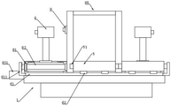
Fig. 1 is a schematic front view of the present invention.
FIG. 2 is a schematic front view of a sliding rack moving to an end of the device for recycling and transporting according to the embodiment of the present invention.
FIG. 3 is a schematic side view of the present invention.
Fig. 4 is a schematic view of the internal structure of the transmission device of the present invention.
Fig. 5 is a schematic top view of the present invention.
Fig. 6 is a schematic structural view of the limiting mechanism of the present invention.
Fig. 7 is a schematic structural view of the flipping table of the present invention.
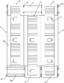
Fig. 8 is a schematic view of the assembled conveyor apparatus in a downward configuration.
Fig. 9 is a schematic side view of the assembled conveyor.
Fig. 10 is a schematic view of a downward structure of the recovery conveyor.
Fig. 11 is a schematic side view of the recycling conveyor.
Detailed Description
The present invention will be described in further detail with reference to the accompanying drawings and specific embodiments.
As shown in fig. 1-7, a transmission case assembling and conveying system comprises a conveying system, wherein the conveying system comprises an underframe 1, more than one assembling and conveying device 2, a recovery conveying device 3, a turnover table 4 for hanging the transmission case, more than two sliding frames 5, a sliding mechanism and a limiting mechanism 7 arranged on the assembling and conveying device 2; the assembling and conveying device 2 and the recovery and conveying device 3 are used for conveying the overturning platform 4, and the sliding frame 5 is used for vertically transferring the transferring and overturning platform 4 between the assembling and conveying device 2 and the recovery and conveying device 3; the limiting mechanism 7 is used for limiting the overturning tables 4 in different processes on the assembling and conveying device 2 and separating each assembling process.
The assembly conveying device 2 and the recovery conveying device 3 are adjacently arranged on the base frame 1 side by side, more than one sliding frame 5 is respectively arranged at two ends of the base frame 1 in the conveying direction of the assembly conveying device 2 and the recovery conveying device 3, and the sliding frames 5 are arranged on the base frame 1 in a sliding mode through a sliding mechanism; the conveying directions of the assembling conveying device 2 and the recovering conveying device 3 are opposite; conveying the overturning platform 4 on the assembling and conveying device 2 or the recovering and conveying device 3 to the sliding frame 5, and transferring the overturning platform to the recovering and conveying device 3 or the assembling and conveying device 2 through the sliding frame 5; in the present embodiment, the fitting conveyor 2 is provided with two in total, and the two fitting conveyors 2 are respectively provided on both sides of the recovery conveyor 3.
The sliding mechanism comprises a guide rail 61 arranged on the base frame 1 and a pulley 62 arranged at the bottom of the sliding frame 5, and the pulley 62 is arranged on the guide rail 61 in a sliding manner; of course, the pulleys may be replaced by sliders, and the sliding frame 5 can stably slide between the assembly conveyor 2 and the recovery conveyor 3.
As shown in fig. 4 and 6, the limiting mechanism 7 includes a telescoping mechanism 71 and a telescoping rod 72 disposed on the telescoping mechanism 71; when the overturning platform 4 needs to be limited, the telescopic mechanism 71 is controlled to drive the telescopic rod 72 to extend out until the end part of the telescopic rod 72 is higher than the highest position of the driving roller 82; with the arrangement, the length of the telescopic rod 72 can be controlled by controlling the telescopic mechanism 71, so that different assembling processes can be separated. In the present embodiment, the telescoping mechanism 71 is a telescoping motor or cylinder. In the present embodiment, the chassis 1 is provided with a mounting plate for mounting the telescopic mechanism 71 below the conveying conveyor rollers 82.
A vertical plate 88 is arranged between the assembling and conveying device 2 and the recovering and conveying device 3 on the underframe 1; a first sensor is arranged at the position, corresponding to the assembly station corresponding to each assembly process, on the outer side of the vertical plate 88; more than three second sensors are arranged on the inner side of the vertical plate, the first sensors and the second sensors are both connected with a controller, the first sensors and the second sensors are both position sensors, and the controller is an MCU.
The working method of the gearbox assembling and conveying system comprises the following steps:
(1) the flipping table is placed on an assembly conveyor located on at least one side of the recovery conveyor.
(2) The assembly conveying device is started to convey the overturning platform forwards in the direction from the starting end to the tail end of the assembly conveying device, when a first sensor which corresponds to the first assembly process and is arranged on the vertical plate detects that the overturning platform exists, the assembly conveying device stops conveying the overturning platform, meanwhile, a limiting mechanism which is located in front of the first assembly process limits the overturning platform on the first assembly process to move forwards, and workpieces of the gearbox are assembled on the overturning platform on the first assembly process.
(3) After the assembly of the first assembly procedure is completed, the limiting mechanism positioned in front of the first assembly procedure retracts; inputting another overturning platform at the starting end of the assembly conveying device, starting the assembly conveying device to convey the other overturning platform forwards to a first assembly process, conveying the overturning platform on the first assembly process to a second assembly process, stopping conveying the overturning platform by the assembly conveying device when a first sensor arranged on a vertical plate corresponding to the first assembly process and the second assembly process detects that the overturning platform exists, simultaneously respectively limiting the forward movement of the overturning platform on the first assembly process and the second assembly process by a limiting mechanism in front of the first assembly process and the second assembly process, and assembling workpieces of a gearbox on the overturning platform on the first assembly process and the second assembly process; if the third assembling process and the fourth assembling process are arranged in sequence, the steps are repeated until the gearbox is assembled on the overturning platform.
(4) The last assembled gearbox with the tilting table is moved into the waiting slide rack at the end of the assembly conveyor.
(5) And disassembling the gearbox from the overturning platform on a sliding frame positioned at the tail end of the assembling and conveying device and conveying the gearbox to a detection station.
(6) The sliding frame on the tail end of the assembling and conveying device drives the overturning platform to move to the initial end of the recovery and conveying device.
(7) And conveying the overturning platform on the sliding frame at the tail end of the assembling and conveying device into the recovery and conveying device.
(8) And a second sensor at the tail end of the vertical plate on the recovery conveying device detects whether the overturning platform exists, if the overturning platform is not detected, the overturning platform at the initial end of the recovery conveying device is continuously conveyed to the tail end of the recovery conveying device, and the overturning platforms which are continuously arranged from the tail end to the initial end of the recovery conveying device are ensured.
(9) The sliding frame at the starting end of the assembling and conveying device moves from the starting end of the assembling and conveying device to the tail end of the recovering and conveying device, when the tail end of the recovering and conveying device detects that the sliding frame exists, the overturning platform at the tail end of the recovering and conveying device moves forwards to the sliding frame, otherwise, the recovering and conveying device does not move; when the sliding frame at the initial end of the assembling and conveying device is provided with the overturning platform, the sliding frame is moved to the initial end of the assembling and conveying device, and the overturning platform is transferred to the initial end of the assembling and conveying device through the sliding frame.
(10) And repeating the steps to realize the assembly of the gearbox on the overturning platform and the recycling and circulating conveying of the overturning platform.
According to the arrangement, on one hand, the gearbox on the overturning platform is assembled on one side of the assembling and conveying device, the overturning platform is limited by controlling the limiting mechanism, and then different assembling processes are separated, so that workers of each assembling process can not be influenced by the progress of other assembling processes; only after the assembly of the process is completed, the limiting mechanism 7 can be controlled to be retracted, so that the overturning platform 4 can be conveyed to the process from the previous assembly process on the assembly conveying device 2; therefore, the assembly efficiency of the gearbox is improved; on the other hand, the assembly conveying device 2 conveys the overturning platform 4 which sequentially finishes the assembly of the gearbox to the sliding frame 5 at one end, the assembled gearbox is taken down from the overturning platform 4 and then the gearbox is sent to be detected, the sliding frame 5 is slidingly moved to the initial end of the recovery conveying device 3 through the sliding mechanism, the recovery conveying device 3 which lightly pushes the sliding frame 5 is conveyed to the sliding frame 5 at the tail end of the recovery conveying device 3 through the recovery conveying device 3, the sliding frame is moved to the initial end of the assembly conveying device through the sliding mechanism, and the gearbox which needs to be assembled is hung on the idling overturning platform 4; like this, assembly conveyor 2, slide 5, retrieve conveyor 3, slide 5 and form the square loop of carrying roll-over table 4, and conveying system is high to roll-over table 4's transmission efficiency, and conveying system compact structure, area is little, can assemble a plurality of gearboxes simultaneously, and then improves economic benefits. In the invention, the empty overturning platform is continuously sent to the tail end of the recovery conveying device, when the tail end of the recovery conveying device is provided with an empty sliding frame, the empty overturning platform can be sent to the sliding frame, the sliding frame is moved to the initial end position of the assembly conveying device, and the gearbox to be assembled is hung on the empty overturning platform.
The assembly conveying device 2 comprises a frame 81 and a conveying assembly, in the invention, the frame 81 is of a frame structure connected end to end through four beams, a frame cavity is formed in the frame 81, the conveying assembly comprises conveying groups with the same number as that of working procedures, each conveying group comprises more than one conveying mechanism, each conveying mechanism comprises more than two conveying rollers 82 and a conveying driving mechanism, the conveying rollers 82 are installed in a frame space of the frame 81 through bearings, the axes of the adjacent conveying rollers 82 are on the same plane, the upper edge of the frame 81 is higher than the highest point of the conveying rollers 82, therefore, when the overturning platform moves on the conveying rollers, the overturning platform can be limited and guided through two side edges of the frame, and the conveying mechanisms are installed on the frame 81 and drive the conveying rollers.
As shown in fig. 8 and 9, the conveying and driving mechanism includes a first motor 831, a first driving sprocket 832, a first driven sprocket 833, a conveying driven sprocket 834, a first driving chain 835 and a first driven chain 836; the first motor 831 is installed on the frame 91, the first driving sprocket 832 is installed on an output shaft of the first motor 831, a first driven sprocket 833 is installed at one end of one of the conveying rollers 82 of the same conveying mechanism, the first driving chain 835 is sleeved between the first driving sprocket 832 and the first driven sprocket 833, the conveying driven sprockets 834 are installed at two ends of the conveying rollers, and a first driven chain 836 is sleeved between the adjacent conveying driven sprockets. In the invention, two conveying driven sprockets are respectively arranged at two ends of the conveying roller between the two ends, and one conveying driven sprocket is arranged on the conveying roller at the two ends.
The independent conveying groups are arranged at the position corresponding to each assembling process, so that each group of conveying groups can be independently controlled, the operation is convenient, in the invention, each assembling process can accommodate at least two overturning tables, for example, when the two overturning tables can be accommodated, the first position is an assembling position, the second position is a waiting position, and the limiting mechanism is arranged at the front end of the second position, so that after the assembling on the assembling process is completed and the next assembling process is not completed, the transmission box assembled with the corresponding workpiece is driven to move forwards to the second position for waiting by controlling the conveying driving mechanism, the forward movement of the transmission box is limited by the limiting mechanism, the influence on the normal work of the next assembling process is avoided, and meanwhile, when the overturning table at the first position is conveyed away, the next overturning table can enter the first position, the assembly can be continued in the first position, thereby improving the overall assembly efficiency.
When the first motor works, the first motor drives the first driving chain wheel to rotate, the first driving chain wheel drives the first driven chain wheel to rotate through the first driving chain, the first driven chain wheel drives the corresponding conveying roller to rotate, and the conveying roller in the same conveying mechanism is driven to rotate through the conveying driving chain wheel and the first driven chain wheel, so that the conveying of the overturning platform is realized.
As shown in fig. 10 and 11, the recovery conveyor 3 includes a recovery frame 91 and a recovery conveyor assembly, in the invention, the recovery frame 91 is a frame structure connected end to end by four beams, a recovery frame cavity is formed in the recovery frame 91, the recovery conveying assembly comprises more than two recovery conveying groups, the recovery conveying group comprises more than one recovery conveying mechanism, the recovery conveying mechanism comprises more than two recovery conveying rollers 92 and a recovery conveying driving mechanism, the recovery conveying rollers 92 are arranged in a recovery cavity of the recovery frame through bearings, the axes of the adjacent recovery conveying rollers are on the same plane, the upper edge of the recovery frame 91 is higher than the highest point of the recovery conveying rollers, thus, the turnover table can be guided and limited by the two side edges of the recovery frame, and the recovery conveying mechanism is arranged on the recovery frame and drives the recovery conveying rollers 92.
For the recovery conveying device, the recovery conveying groups can be independently controlled by arranging a plurality of groups of recovery conveying groups, so that when vacant positions exist between adjacent overturning tables in the recovery conveying device, the unloaded overturning tables can be continuously arranged by independent control.
The recovery conveying driving mechanism comprises a second motor 931, a second driving chain wheel 932, a second driven chain wheel 933, a recovery driven chain wheel 934, a second driving chain 935 and a second driven chain 936; the second motor 931 is installed on the recovery frame 91, the second driving sprocket 932 is installed on the output shaft of the second motor 931, a second driven sprocket 933 is installed at one end of one of the recovery conveying rollers of the same recovery conveying mechanism, the second driving chain 935 is sleeved between the second driving sprocket 932 and the second driven sprocket 933, the recovery driven sprocket 934 is installed on the recovery conveying roller, and a second driven chain 936 is sleeved between the adjacent recovery driven sprockets. In the invention, two recovery driven sprockets are respectively arranged at two ends of the recovery conveying roller between the two ends, and one recovery driven sprocket is arranged on the recovery conveying roller at the two ends.
When the second motor is in work, the second motor drives the second driving chain wheel to rotate, the second driving chain wheel drives the second driven chain wheel to rotate through the second driving chain, the second driven chain wheel drives the corresponding recovery conveying roller to rotate, and the recovery conveying roller in the same recovery conveying mechanism is driven to rotate through the recovery driven chain wheel and the second driven chain wheel, so that the conveying of the overturning platform is realized. The movement directions of the assembling and recovering conveying devices are opposite.
A sliding driving device (not shown in the figure) for driving the pulley 62 is also arranged in the sliding frame 5; in this example, the sliding driving device can be a cylinder, an oil cylinder, a linear motor, a screw nut structure and the like, so that the sliding frame 5 can be driven to slide by the sliding driving device, and the physical burden of workers is reduced.
Two ends of the guide rail 61 in the length direction are respectively provided with a guide rail limiting part 611 for limiting the sliding frame 5; in this way, the sliding frame 5 is limited by the rail limiting member 611, and the sliding frame 5 is prevented from being detached from the rail 61.
In this embodiment, two sides of the sliding frame 5 are respectively provided with an abutting part 51 corresponding to the slide rail limiting part; in the above arrangement, when a sliding frame 5 moves to one end of the assembly conveying device 2, the abutting piece 51 on one side of the sliding frame 5 abuts against the guide rail limiting piece 611; when one sliding frame 5 moves to one end of the recovery conveying device 3, the abutting piece 51 on one side of the sliding frame 5 abuts against the abutting piece 51 on the other sliding frame 5 at one end of the assembly conveying device 2; thus, the contact piece 51 can protect the carriage 5.
In this embodiment, a shielding portion 85 formed by a plurality of plate bodies is further provided on the vertical plate, and the shielding portion 85 is provided with a control switch 9 for controlling the conveying and conveying driving mechanism and the recovery and conveying driving mechanism and for controlling the expansion and contraction of the expansion and contraction mechanism 71 on the side close to the assembling and conveying device 2.
The end part of the telescopic rod 72 is also provided with a travel switch 73, and the travel switch 73 is used for controlling the conveying driving mechanism 83; with the arrangement, when the overturning platform 4 needs to be limited, the stretching mechanism 71 is controlled to stretch out, so that the travel switch 73 at the end part of the stretching mechanism 71 stretches out to be higher than the driving roller 82, the overturning platform 4 pushes the travel switch 73 under the conveying action of the driving roller 82, and then the travel switch 73 controls the conveying driving mechanism 83 to stop working, so that the conveying overturning platform 4 is stopped.
Claims (10)
1. A method of operating a transmission assembly conveyor system, comprising the steps of:
(1) placing the overturning platform on an assembling conveying device positioned on at least one side of the recovery conveying device;
(2) starting the assembly conveying device to convey the overturning platform forwards in the direction from the starting end to the tail end of the assembly conveying device, stopping conveying the overturning platform by the assembly conveying device when a first sensor which corresponds to the first assembly procedure and is arranged on the vertical plate detects that the overturning platform exists, limiting the overturning platform on the first assembly procedure to move forwards by a limiting mechanism which is positioned in front of the first assembly procedure, and assembling a workpiece of the gearbox on the overturning platform on the first assembly procedure;
(3) after the assembly of the first assembly procedure is completed, the limiting mechanism positioned in front of the first assembly procedure retracts; inputting another overturning platform at the starting end of the assembly conveying device, starting the assembly conveying device to convey the other overturning platform forwards to a first assembly process, conveying the overturning platform on the first assembly process to a second assembly process, stopping conveying the overturning platform by the assembly conveying device when a first sensor arranged on a vertical plate corresponding to the first assembly process and the second assembly process detects that the overturning platform exists, limiting mechanisms positioned in front of the first assembly process and the second assembly process respectively limit the overturning platforms on the first assembly process and the second assembly process to move forwards, and assembling workpieces of a gearbox on the overturning platform on the first assembly process and the second assembly process; if the third assembling procedure, the fourth assembling procedure and more assembling procedures are sequentially arranged, the steps are repeated until the gearbox is assembled on the overturning platform;
(4) the transmission case which is assembled at the most front and the overturning platform enter a waiting sliding frame at the tail end of the assembling and conveying device;
(5) the gearbox is disassembled from the overturning platform on a sliding frame positioned at the tail end of the assembling and conveying device;
(6) the sliding frame positioned at the tail end of the assembling and conveying device drives the overturning platform to move to the initial end of the recovering and conveying device;
(7) conveying the overturning platform on the sliding frame positioned at the tail end of the assembling and conveying device into the recovery and conveying device;
(8) a second sensor at the tail end of the vertical plate on the recovery conveying device detects whether the overturning platform exists or not, if the overturning platform is not detected, the overturning platform at the initial end of the recovery conveying device is continuously conveyed to the tail end of the recovery conveying device, and the overturning platforms which are continuously arranged from the tail end to the initial end of the recovery conveying device are ensured;
(9) the sliding frame at the starting end of the assembling and conveying device moves from the starting end of the assembling and conveying device to the tail end of the recovering and conveying device, when the tail end of the recovering and conveying device detects that the sliding frame exists, the overturning platform at the tail end of the recovering and conveying device moves forwards to the sliding frame, otherwise, the recovering and conveying device does not move; when the sliding frame at the initial end of the assembling and conveying device is provided with the overturning platform, the sliding frame is moved to the initial end of the assembling and conveying device, and the overturning platform is transferred to the initial end of the assembling and conveying device through the sliding frame;
(10) and repeating the steps to realize the assembly of the gearbox on the overturning platform and the recycling and circulating conveying of the overturning platform.
2. The method of claim 1, wherein the step of operating the transmission assembly conveyor system comprises: the assembly conveying device comprises a frame and a conveying assembly, wherein the conveying assembly comprises conveying groups with the same number as that of the working procedures, the conveying groups comprise more than one conveying mechanism, the conveying mechanism comprises more than two conveying rollers and a conveying driving mechanism, the conveying rollers are installed in the frame through bearings, the axes of the adjacent conveying rollers are on the same plane, the upper edge of the frame is higher than the highest point of the conveying rollers, and the conveying mechanism is installed on the frame and drives the conveying rollers; the recycling conveying device comprises a recycling frame and a recycling conveying assembly, the recycling conveying assembly comprises more than two recycling conveying groups, each recycling conveying group comprises more than one recycling conveying mechanism, each recycling conveying mechanism comprises more than two recycling conveying rollers and a recycling conveying driving mechanism, the recycling conveying rollers are installed in the recycling frame through bearings, the axes of the adjacent recycling conveying rollers are on the same plane, the upper edge of the recycling frame is higher than the highest point of the recycling conveying rollers, and the recycling conveying mechanisms are installed on the recycling frame and drive the recycling conveying rollers.
3. The method of operating a transmission assembly delivery system of claim 2, wherein: the conveying and driving mechanism comprises a first motor, a first driving chain wheel, a first driven chain wheel, a conveying driven chain wheel, a first driving chain and a first driven chain; the first motor is arranged on the frame, the first driving chain wheel is arranged on an output shaft of the first motor, a first driven chain wheel is arranged on one conveying roller of the same conveying mechanism, the first driving chain is sleeved between the first driving chain wheel and the first driven chain wheel, the conveying driven chain wheels are arranged on the conveying rollers, and the first driven chain wheels are sleeved between the adjacent conveying driven chain wheels; the recovery conveying driving mechanism comprises a second motor, a second driving chain wheel, a second driven chain wheel, a recovery driven chain wheel, a second driving chain and a second driven chain; the second motor is installed on the recycling frame, the second driving chain wheel is installed on an output shaft of the second motor, the second driven chain wheel is installed on one recycling conveying roller of the same recycling conveying mechanism, the second driving chain is sleeved between the second driving chain wheel and the second driven chain wheel, the recycling driven chain wheel is installed on the recycling conveying roller, and the second driven chain wheel is sleeved between the adjacent recycling driven chain wheels.
4. The method of operating a transmission assembly conveyor system of claim 1, wherein: the overturning platform comprises a bottom plate, an upright post arranged in the middle of the bottom plate, a roller arranged on the bottom plate and an overturning seat arranged at the upper end part of the upright post; the roller is arranged on the inner side wall of the frame and is abutted against the inner side wall of the frame; the turnover seat is provided with a rotating rod for hanging the gearbox, one side of the turnover seat is provided with a rotating handle for controlling the rotating rod to rotate and fix, and the turnover seat rotates 360 degrees along the vertical axis of the stand column.
5. The method of operating a transmission assembly delivery system of claim 1, wherein: the sliding mechanism comprises a guide rail arranged on the bottom frame and a pulley arranged at the bottom of the sliding frame, and the pulley is arranged on the guide rail in a sliding manner.
6. The method of operating a transmission assembly conveyor system of claim 5, wherein: and a sliding driving device for driving the sliding frame is also arranged in the sliding frame.
7. The method of operating a transmission assembly conveyor system of claim 5, wherein: two ends of the guide rail in the length direction are respectively provided with a guide rail limiting part for limiting the sliding frame; and two sides of the sliding frame are respectively provided with a butting part corresponding to the slide rail limiting parts.
8. The method of operating a transmission assembly conveyor system of claim 1, wherein: the limiting mechanism comprises a telescopic mechanism and a telescopic rod arranged on the telescopic mechanism; when the overturning platform needs to be limited, the telescopic mechanism is controlled to drive the telescopic rod to stretch out to the position where the end part of the telescopic rod is higher than the highest position of the conveying roller.
9. The method of operating a transmission assembly conveyor system of claim 8, wherein: the end part of the telescopic rod is also provided with a travel switch which is used for controlling the conveying and driving mechanism.
10. The method of operating a transmission assembly conveyor system of claim 1, wherein: the assembly conveying devices are provided with two assemblies, and the two assemblies are respectively arranged on two sides of the recovery conveying device.
Priority Applications (1)
| Application Number | Priority Date | Filing Date | Title |
|---|---|---|---|
| CN202210815814.5A CN114952287A (en) | 2022-07-12 | 2022-07-12 | Working method of gearbox assembling and conveying system |
Applications Claiming Priority (1)
| Application Number | Priority Date | Filing Date | Title |
|---|---|---|---|
| CN202210815814.5A CN114952287A (en) | 2022-07-12 | 2022-07-12 | Working method of gearbox assembling and conveying system |
Publications (1)
| Publication Number | Publication Date |
|---|---|
| CN114952287A true CN114952287A (en) | 2022-08-30 |
Family
ID=82969579
Family Applications (1)
| Application Number | Title | Priority Date | Filing Date |
|---|---|---|---|
| CN202210815814.5A Pending CN114952287A (en) | 2022-07-12 | 2022-07-12 | Working method of gearbox assembling and conveying system |
Country Status (1)
| Country | Link |
|---|---|
| CN (1) | CN114952287A (en) |
Citations (8)
| Publication number | Priority date | Publication date | Assignee | Title |
|---|---|---|---|---|
| WO2003104113A2 (en) * | 2002-06-07 | 2003-12-18 | Sankyo Seiki Mfg. Co., Ltd. | Production lines utilizing auto guided pallet and production line design support system |
| CN101815658A (en) * | 2007-10-31 | 2010-08-25 | 大发工业株式会社 | Pallet transfer equipment |
| CN202594329U (en) * | 2012-03-29 | 2012-12-12 | 浙江富士达电子机械有限公司 | Gearbox assembly assembling production line |
| CN104495269A (en) * | 2014-12-19 | 2015-04-08 | 苏州互强工业设备有限公司 | Automatic assembly line |
| CN105173597A (en) * | 2015-09-14 | 2015-12-23 | 董振海 | Tray circulating device |
| CN206915216U (en) * | 2017-07-21 | 2018-01-23 | 广州富士汽车整线集成有限公司 | A kind of car body welding producing line |
| CN110450093A (en) * | 2019-09-10 | 2019-11-15 | 中国建筑第七工程局有限公司 | A kind of dismounting engine rack |
| CN114235452A (en) * | 2021-12-10 | 2022-03-25 | 南斗六星系统集成有限公司 | Intelligence passenger cabin product automated inspection assembly line |
-
2022
- 2022-07-12 CN CN202210815814.5A patent/CN114952287A/en active Pending
Patent Citations (8)
| Publication number | Priority date | Publication date | Assignee | Title |
|---|---|---|---|---|
| WO2003104113A2 (en) * | 2002-06-07 | 2003-12-18 | Sankyo Seiki Mfg. Co., Ltd. | Production lines utilizing auto guided pallet and production line design support system |
| CN101815658A (en) * | 2007-10-31 | 2010-08-25 | 大发工业株式会社 | Pallet transfer equipment |
| CN202594329U (en) * | 2012-03-29 | 2012-12-12 | 浙江富士达电子机械有限公司 | Gearbox assembly assembling production line |
| CN104495269A (en) * | 2014-12-19 | 2015-04-08 | 苏州互强工业设备有限公司 | Automatic assembly line |
| CN105173597A (en) * | 2015-09-14 | 2015-12-23 | 董振海 | Tray circulating device |
| CN206915216U (en) * | 2017-07-21 | 2018-01-23 | 广州富士汽车整线集成有限公司 | A kind of car body welding producing line |
| CN110450093A (en) * | 2019-09-10 | 2019-11-15 | 中国建筑第七工程局有限公司 | A kind of dismounting engine rack |
| CN114235452A (en) * | 2021-12-10 | 2022-03-25 | 南斗六星系统集成有限公司 | Intelligence passenger cabin product automated inspection assembly line |
Similar Documents
| Publication | Publication Date | Title |
|---|---|---|
| CN105923369B (en) | Intelligent transfer line | |
| CN109592445B (en) | Efficient container body stacking system and method | |
| CN110861926B (en) | Sheet stock plate transferring, stacking and lifting device and using method | |
| CN113526076B (en) | Automatic automobile hub feeding device | |
| CN107378604A (en) | A kind of section steel cutting automatic charging device | |
| CN105945286A (en) | Automatic material conveying device | |
| CN109969755B (en) | Door plant manufacturing line | |
| CN111390087A (en) | Intelligent sucker rod manufacturing production line | |
| CN110697393A (en) | Double fungus basket machine of putting on shelf | |
| CN211168775U (en) | Double fungus basket machine of putting on shelf | |
| CN217727816U (en) | Gearbox assembly conveying system | |
| CN114952287A (en) | Working method of gearbox assembling and conveying system | |
| CN114952286A (en) | Gearbox assembly conveying system | |
| CN217534482U (en) | Conveying system of gearbox assembly line | |
| CN116002310A (en) | Modularized grouping assembly production line | |
| CN112938395B (en) | Automatic tail-pulling assembly line for multi-station glass bottle liners | |
| CN214011121U (en) | Caterpillar track section magnetic particle inspection equipment | |
| CN211643665U (en) | Industrial lifting reciprocating conveying device | |
| CN106994565A (en) | A kind of compact handling equipment | |
| CN109318032B (en) | Automatic convenient unloading system and production facility | |
| CN210557527U (en) | Carbon steel ladle brick conveying and transferring production line | |
| CN113245772A (en) | Automatic welding production line | |
| CN110394681A (en) | A kind of big piston pin multiaxis truss robot one drag two numerical control machine | |
| CN219297094U (en) | Transfer robot | |
| CN117066768B (en) | Pressure vessel production system and manufacturing method |
Legal Events
| Date | Code | Title | Description |
|---|---|---|---|
| PB01 | Publication | ||
| PB01 | Publication | ||
| SE01 | Entry into force of request for substantive examination | ||
| SE01 | Entry into force of request for substantive examination |