CN114426205A - Finished product pile auxiliary device is used in rice processing - Google Patents
Finished product pile auxiliary device is used in rice processing Download PDFInfo
- Publication number
- CN114426205A CN114426205A CN202111545135.2A CN202111545135A CN114426205A CN 114426205 A CN114426205 A CN 114426205A CN 202111545135 A CN202111545135 A CN 202111545135A CN 114426205 A CN114426205 A CN 114426205A
- Authority
- CN
- China
- Prior art keywords
- fixed
- sliding
- finished product
- rice processing
- rear side
- Prior art date
- Legal status (The legal status is an assumption and is not a legal conclusion. Google has not performed a legal analysis and makes no representation as to the accuracy of the status listed.)
- Withdrawn
Links
Images


Classifications
-
- B—PERFORMING OPERATIONS; TRANSPORTING
- B65—CONVEYING; PACKING; STORING; HANDLING THIN OR FILAMENTARY MATERIAL
- B65G—TRANSPORT OR STORAGE DEVICES, e.g. CONVEYORS FOR LOADING OR TIPPING, SHOP CONVEYOR SYSTEMS OR PNEUMATIC TUBE CONVEYORS
- B65G57/00—Stacking of articles
- B65G57/02—Stacking of articles by adding to the top of the stack
- B65G57/03—Stacking of articles by adding to the top of the stack from above
Abstract
The invention discloses a finished product stacking auxiliary device for rice processing, which comprises a bottom plate body, a turnover device, a material taking device, a control device and a sliding device, wherein the material taking device is positioned inside the turnover device, the sliding device is positioned at the top of the material taking device, a side plate is fixed at the position, close to the rear side edge, of the top of the bottom plate body, and a sliding opening is formed in the middle of the front side of the side plate. Resulting in a problem that the outer shell of the rice packing bag is broken.
Description
Technical Field
The invention relates to the technical field of stacking devices, in particular to a finished product stacking auxiliary device for rice processing.
Background
The stacking device is generally called a stacking machine, and the existing stacking machine stacks cartons loaded into containers on pallets and pallets (wood and plastic) according to a certain arrangement, automatically stacks the cartons, stacks the cartons in multiple layers, and pushes the cartons out so as to be conveniently transported to a warehouse for storage by a forklift. The equipment is controlled by the PLC and the touch screen, intelligent operation management is realized, and the equipment is simple and convenient and easy to master. Can greatly reduce labor force and labor intensity. The stacker crane is equipment for automatically stacking bags, cartons or other packaging materials conveyed by a conveyor into stacks according to the working mode of the client process requirement and conveying the stacked materials.
A pile up a yard device of stamping for rice finished product is piled up at present when in actual use, it piles up the rice and then stamp a yard device and remove the rice through piling up the tray to need to use lifting by crane the mechanism on fixed tray usually for people need stamp the yard earlier with the rice and divide the piece to the rice, can not directly stamp the yard to solitary rice wrapping bag through stamping a yard device, the in-service use of giving people has brought the trouble, and stamp a yard device and put down the rice bag when very easily and take place wearing and tearing between the deflector, lead to the rice wrapping bag shell breakage.
We have therefore proposed a finished product stacking aid for rice processing to solve the problems set forth above.
Disclosure of Invention
The invention aims to provide a finished product stacking auxiliary device for rice processing, and the finished product stacking auxiliary device is used for solving the problems that the conventional finished rice product stacking device is generally required to stack rice on a fixed tray by using a lifting mechanism and then the stacking device moves the rice through the stacked tray, so that people need to divide the rice into blocks before stacking the rice, can not directly stack individual rice packaging bags through the stacking device, troubles are brought to the actual use of people, and the rice packaging bags are easily abraded with a guide plate when the stacking device puts down the rice bags, so that the shells of the rice packaging bags are broken.
In order to achieve the purpose, the invention provides the following technical scheme: a finished product stacking auxiliary device for rice processing comprises a bottom plate body, a turnover device, a material taking device, a control device and a sliding device, wherein the material taking device is positioned inside the turnover device, and the sliding device is positioned at the top of the material taking device;
a side plate is fixed at the position, close to the rear side edge, of the top of the bottom plate body, a sliding opening is formed in the middle of the front side of the side plate, the inner bottom surface of the sliding opening is located in the middle of the side plate and is rotatably connected with a lead screw through a bearing, the top of the lead screw penetrates through the top of the side plate, supporting rods are fixed at the position, close to the two side edges, of the top of the side plate, a fixing sleeve is fixed between one end of each supporting rod, a motor is fixed inside the fixing sleeve, the output end of the motor is connected with the top of the lead screw, sliding grooves are formed in the inner walls of the two sides of the sliding opening, sliding blocks are connected inside the two sliding grooves in a sliding mode, sliding blocks are connected inside the sliding opening in a sliding mode, the outer surfaces of the two sides of the two sliding blocks are correspondingly fixed on the outer surfaces of the two sides of the sliding blocks, the sliding blocks are connected on the outer surface of the lead screw in a sliding mode, and a turnover device is fixed on the front side of the sliding blocks, the control device is located in the middle of the rear side of the side plate, and a plurality of cushion blocks are fixed at the bottom of the fixing sleeve.
Preferably, the turnover device comprises a U-shaped support, a fixing groove is formed in the inner wall of the rear side of the U-shaped support, limiting grooves are formed in the inner walls of the two sides of the U-shaped support, and a fixing block is fixed to the position, close to the rear side edge, of the bottom of the U-shaped support.
Preferably, a first cylinder is fixed inside the fixing groove, a second cylinder is fixed at the top of the fixing block, and a connector is fixed at the top of the second cylinder.
Preferably, the material taking device comprises a material taking plate, the top of the material taking plate is close to edges of two sides and is provided with a butt joint groove, the mounting groove is formed in the bottom surface of the butt joint groove, the outer surfaces of two sides of the material taking device are fixed with limiting blocks, and the limiting blocks correspond to the inner parts of the two limiting grooves in a sliding connection mode.
Preferably, the rear side of getting the flitch is close to top edge and is connected with the connecting plate through the hinge rotation, two the front side of mounting groove all runs through to the front side of getting the flitch, the connector rotates through the pin and connects in the bottom middle part of getting the flitch, the front end at first cylinder is fixed to the rear side of connecting plate.
Preferably, controlling means includes two L shape blend stops, the rear side position of curb plate is fixed with the limiting plate in the middle part, two the bottom of L shape blend stop all laminates mutually with the top of limiting plate, two the side mouth has all been seted up between the relative one side of L shape blend stop.
Preferably, two sliding connection has control panel between the inside of side mouth, two the opposite side of L shape blend stop all is fixed with the fixed plate, two the rear side of fixed plate all is fixed with magnet, two magnet all adsorbs on the rear side of curb plate.
Preferably, the glide set includes two channel-section steels, two the top of channel-section steel is close to both sides edge and all is fixed with the butt joint board, four the butt joint board divide into two sets ofly, is located every two butt joint boards on the channel-section steel are a set of, and every group is two the butt joint board all corresponds the block in the inside of butt joint groove.
Preferably, two the channel-section steel all corresponds the block in the inside of two mounting grooves, two all be connected with two pivots, four through the bearing rotation between the both sides inner wall of channel-section steel the surface of pivot all is fixed with the gyro wheel.
Compared with the prior art, the invention has the beneficial effects that:
1. when the device is used, the screw rod is firstly rotated through the rotation of the motor, and the outer surface of the screw rod is in sliding connection with the sliding block, so that the sliding block slides up and down along the sliding opening in the process that the motor drives the screw rod to rotate, the overturning device is fixed on the front side of the sliding block, the whole stacking device moves up and down, the plurality of cushion blocks are fixed at the bottom of the fixing sleeve, the motor can be prevented from shaking in the rotation process, the sliding block can stably slide in the sliding opening through the matching of the sliding chute and the sliding block in the sliding process of the sliding block, the forward tilting force of the sliding block, which is brought to the sliding block by the overturning device, can be counteracted through the matching of the sliding chute and the sliding block, and the screw rod is prevented from being bent;
2. when the loaded rice is stacked, the material taking device can slide in the U-shaped support through the extension and contraction of the first air cylinder, the material taking device can stably slide through the cooperation of the limiting block and the limiting groove in the sliding process, the bearing capacity of the material taking device can be increased through the cooperation of the limiting block and the limiting groove, and when the material is taken and placed, the material taking plate can be driven to turn over under the action of the hinge through the extension and contraction of the second air cylinder, so that the rice bag on the material taking device can be detached;
3. inside the side mouth with control panel sliding connection between two L shape blend stops, the control panel of taking of people of being convenient for to fix whole controlling means through magnet, the people of being convenient for dismantle, made things convenient for people's use, when getting the flitch and loading the rice, make the rice bag slide on getting the flitch through the gyro wheel on the displacement device, thereby made things convenient for people to get the material, when unloading, can make the smooth place that slides to needs piling up of the rice bag on getting the flitch through the gyro wheel.
Drawings
Fig. 1 is a front perspective view of a finished product stacking auxiliary device for rice processing according to the present invention;
fig. 2 is a bottom perspective view of a finished product stacking aid for rice processing according to the present invention;
fig. 3 is a rear perspective view of a finished product stacking aid for rice processing according to the present invention;
FIG. 4 is a schematic perspective view of a turning device in the auxiliary stacking device for rice processing according to the present invention;
fig. 5 is a schematic front perspective view of a material taking device in the finished product stacking auxiliary device for rice processing according to the present invention;
FIG. 6 is a schematic perspective view of a control device of the auxiliary stacking device for rice processing according to the present invention;
fig. 7 is a schematic front perspective view of a sliding device in the auxiliary stacking device for stacking finished products for rice processing according to the present invention.
In the figure:
1. a bottom plate body; 2. a turning device; 3. a material taking device; 4. a control device; 5. a slipping device; 6. a sliding port; 7. a screw rod; 8. a chute; 9. a slider; 10. a sliding block; 11. a strut; 12. fixing a sleeve; 13. a motor; 14. cushion blocks; 15. a first cylinder; 16. a side plate; 17. a limiting plate; 21. a U-shaped bracket; 22. a limiting groove; 23. a second cylinder; 24. a fixed block; 25. a connector; 26. fixing grooves; 31. taking a material plate; 32. mounting grooves; 33. a limiting block; 34. a butt joint groove; 35. a connecting plate; 41. an L-shaped barrier strip; 42. a fixing plate; 43. a magnet; 44. a control panel; 45. a side port; 51. channel steel; 52. a butt plate; 53. a roller; 54. a rotating shaft.
Detailed Description
The technical solutions in the embodiments of the present invention will be clearly and completely described below with reference to the drawings in the embodiments of the present invention, and it is obvious that the described embodiments are only a part of the embodiments of the present invention, and not all embodiments. All other embodiments, which can be derived by a person skilled in the art from the embodiments given herein without making any creative effort, shall fall within the protection scope of the present invention.
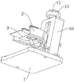
Referring to fig. 1-7, the present invention provides a technical solution: a finished product stacking auxiliary device for rice processing comprises a bottom plate body 1, a turnover device 2, a material taking device 3, a control device 4 and a sliding device 5, wherein the material taking device 3 is positioned inside the turnover device 2, the sliding device 5 is positioned at the top of the material taking device 3, a side plate 16 is fixed at the top of the bottom plate body 1 close to the rear side edge, a sliding opening 6 is formed in the middle of the front side of the side plate 16, the inner bottom surface of the sliding opening 6 is positioned in the middle and is rotatably connected with a screw rod 7 through a bearing, the top of the screw rod 7 penetrates through the top of the side plate 16, supporting rods 11 are fixed at the top of the side plate 16 close to the two side edges, a fixing sleeve 12 is fixed between one ends of the two supporting rods 11, a motor 13 is fixed inside the fixing sleeve 12, the output end of the motor 13 is connected with the top of the screw rod 7, sliding grooves 8 are formed in the inner walls of the two sides of the sliding opening 6, and a sliding block 9 is connected inside the two sliding grooves 8 in a sliding manner, the inside sliding connection of mouth 6 that slides has sliding block 10, and the both sides surface of two sliders 9 all corresponds to be fixed on sliding block 10's both sides surface, and sliding block 10 sliding connection is on the surface of lead screw 7, and sliding block 10's front side is fixed with turning device 2, and controlling means 4 is located the rear side middle part of curb plate 16, and the bottom of fixed cover 12 is fixed with a plurality of cushion 14.
The effect that it reaches is, at first make lead screw 7 rotate through the rotation of motor 13 when using this device, because the surface sliding connection sliding block 10 of lead screw 7, so sliding block 10 slides up and down along sliding opening 6 in the in-process that motor 13 drove lead screw 7 to rotate, and fix turning device 2 in the front side of sliding block 10, thereby make whole pile up a yard device activity from top to bottom, fix a plurality of cushion pieces 14 in the bottom of fixed cover 12, can prevent that motor 13 from rocking when rotating, make sliding block 10 slide steadily in the inside of sliding opening 6 through the cooperation of spout 8 and slider 9 in the gliding in-process of sliding block 10, the cooperation of spout 8 and slider 9 can also offset the forward power that turning device 2 brought sliding block 10, prevent that lead screw 7 is crooked.
As shown in fig. 3-6, the turnover device 2 includes a U-shaped support 21, a fixing groove 26 is formed on the inner wall of the rear side of the U-shaped support 21, both side inner walls of the U-shaped support 21 are provided with a limiting groove 22, a fixing block 24 is fixed at the bottom of the U-shaped support 21 near the rear side edge, a first cylinder 15 is fixed inside the fixing groove 26, a second cylinder 23 is fixed at the top of the fixing block 24, a connector 25 is fixed at the top of the second cylinder 23, the material taking device 3 includes a material taking plate 31, abutting grooves 34 are formed at the top of the material taking plate 31 near both side edges, mounting grooves 32 are formed at the bottom of the two abutting grooves 34, limiting blocks 33 are fixed on the outer surfaces of both sides of the material taking device 3, both limiting blocks 33 are correspondingly slidably connected inside the two limiting grooves 22, a connecting plate 35 is rotatably connected at the rear side of the material taking plate 31 near the top edge through hinges, the front sides of the two mounting grooves 32 penetrate through the front side of the material taking plate 31, the connecting head 25 is rotatably connected to the middle of the bottom of the material taking plate 31 through a pin, and the rear side of the connecting plate 35 is fixed to the front end of the first cylinder 15.
The effect that it reached does, when piling up the sign indicating number to the rice of adorning, through the flexible of first cylinder 15 for can slide extracting device 3 in the inside of U-shaped support 21, make extracting device 3 can steadily slide through stopper 33 and spacing groove 22's cooperation at gliding in-process, and stopper 33 and spacing groove 22's cooperation can increase extracting device 3's bearing capacity, when getting the material and placing, only need second cylinder 23 flexible, make and to drive and get flitch 31 upset under the effect of hinge, can lift off the rice bag on extracting device 3.
As shown in fig. 2-7, the control device 4 includes two L-shaped bars 41, the limiting plate 17 is fixed at the middle position of the rear side of the side plate 16, the bottoms of the two L-shaped bars 41 are both attached to the top of the limiting plate 17, a side opening 45 is formed between the two opposite sides of the two L-shaped bars 41, a control panel 44 is slidably connected between the insides of the two side openings 45, a fixing plate 42 is fixed at the other side of each L-shaped bar 41, magnets 43 are fixed at the rear sides of the two fixing plates 42, the two magnets 43 are adsorbed on the rear side of the side plate 16, the sliding device 5 includes two channel steels 51, abutting plates 52 are fixed at the tops of the two channel steels 51 near the edges of the two sides, the four abutting plates 52 are divided into two sets, the two abutting plates 52 on each channel steel 51 are a set, the two abutting plates 52 in each set are correspondingly clamped inside the abutting groove 34, the two channel steels 51 are correspondingly clamped inside the two mounting grooves 32, two rotating shafts 54 are rotatably connected between the inner walls of the two sides of the two channel steel 51 through bearings, and rollers 53 are fixed on the outer surfaces of the four rotating shafts 54.
Its effect that reaches does, inside side mouth 45 with control panel 44 sliding connection between two L shape blend stops 41, the people of being convenient for take control panel 44, and fix whole controlling means 4 through magnet 43, the people of being convenient for dismantle, the use of people has been made things convenient for, when getting flitch 31 and loading the rice, it makes the rice bag slide on getting flitch 31 through gyro wheel 53 on the slider 5, thereby made things convenient for people to get the material, when unloading, can make the smooth place that slides to needs piling up of rice bag on getting flitch 31 through gyro wheel 53.
The use method and the working principle of the device are as follows: when the device is used, firstly, the screw rod 7 is rotated through the rotation of the motor 13, as the outer surface of the screw rod 7 is connected with the sliding block 10 in a sliding manner, the sliding block 10 slides up and down along the sliding opening 6 in the process that the screw rod 7 is driven by the motor 13 to rotate, the turnover device 2 is fixed on the front side of the sliding block 10, so that the whole stacking device moves up and down, the plurality of cushion blocks 14 are fixed at the bottom of the fixing sleeve 12, the motor 13 can be prevented from shaking during rotation, the sliding block 10 can stably slide in the sliding opening 6 through the matching of the sliding chute 8 and the sliding block 9 in the sliding process of the sliding block 10, the forward tilting force of the sliding block 10 brought by the turnover device 2 can be offset through the matching of the sliding chute 8 and the sliding block 9, the screw rod 7 is prevented from bending, when the loaded rice is stacked, the material taking device 3 can slide in the U-shaped bracket 21 through the extension and retraction of the first air cylinder 15, the material taking device 3 can slide smoothly through the matching of the limiting block 33 and the limiting groove 22 in the sliding process, and the cooperation of the limiting block 33 and the limiting groove 22 can increase the bearing force of the material taking device 3, when the material is taken and placed, the second cylinder 23 is only required to stretch, so that the material taking plate 31 can be driven to turn over under the action of the hinge, the rice bag on the material taking device 3 can be detached, the control panel 44 is connected in the side opening 45 between the two L-shaped barrier strips 41 in a sliding way, people can take the control panel 44 conveniently, and the whole control device 4 is fixed by the magnet 43, which is convenient for people to disassemble and use, when the material taking plate 31 loads rice, the roller 53 on the sliding device 5 makes the rice bag slide on the material taking plate 31, thereby facilitating the taking of the rice by people, when discharging, the rice bags on the material taking plate 31 can smoothly slide to the place needing to be stacked through the roller 53.
Although the present invention has been described in detail with reference to the foregoing embodiments, it will be apparent to those skilled in the art that various changes in the embodiments and/or modifications of the invention can be made, and equivalents and modifications of some features of the invention can be made without departing from the spirit and scope of the invention.
Claims (9)
1. A finished product stacking auxiliary device for rice processing is characterized by comprising a bottom plate body (1), a turnover device (2), a material taking device (3), a control device (4) and a sliding device (5), wherein the material taking device (3) is located inside the turnover device (2), and the sliding device (5) is located at the top of the material taking device (3);
the top of bottom plate body (1) is close to rear side edge department and is fixed with curb plate (16), the front side position of curb plate (16) has seted up sliding opening (6) in the middle part, the inside bottom surface position of sliding opening (6) has lead screw (7) through the bearing rotation connection in the middle part, the top of lead screw (7) runs through to the top of curb plate (16), the top of curb plate (16) is close to both sides edge and is fixed with branch (11), two be fixed with fixed cover (12) between the one end of branch (11), the inside of fixed cover (12) is fixed with motor (13), the output of motor (13) is connected with the top of lead screw (7), spout (8) have all been seted up to the both sides inner wall of sliding opening (6), two the inside equal sliding connection of spout (8) has slider (9), the inside sliding connection of sliding opening (6) has sliding block (10), two the both sides surface of slider (9) all corresponds to be fixed on the both sides surface of sliding block (10), sliding block (10) sliding connection is on the surface of lead screw (7), the front side of sliding block (10) is fixed with turning device (2), controlling means (4) are located the rear side middle part of curb plate (16), the bottom of fixed cover (12) is fixed with a plurality of cushion (14).
2. The finished product stacking auxiliary device for rice processing as claimed in claim 1, wherein: turning device (2) include U-shaped support (21), fixed slot (26) have been seted up to the rear side inner wall of U-shaped support (21), spacing groove (22) have all been seted up to the both sides inner wall of U-shaped support (21), the bottom of U-shaped support (21) is close to rear side edge department and is fixed with fixed block (24).
3. The finished product stacking auxiliary device for rice processing as claimed in claim 2, wherein: the inside of fixed slot (26) is fixed with first cylinder (15), the top of fixed block (24) is fixed with second cylinder (23), the top of second cylinder (23) is fixed with connector (25).
4. The finished product stacking auxiliary device for rice processing as claimed in claim 3, wherein: extracting device (3) are including getting flitch (31), get the top of flitch (31) and all seted up butt joint groove (34) near both sides edge, two mounting groove (32) have all been seted up to the inside bottom surface in butt joint groove (34), the both sides surface of extracting device (3) all is fixed with stopper (33), two stopper (33) all correspond the inside of sliding connection at two spacing grooves (22).
5. The finished product stacking auxiliary device for rice processing as claimed in claim 4, wherein: get the rear side of flitch (31) and be close to top edge and be connected with connecting plate (35), two through hinge rotation the front side of mounting groove (32) all runs through to the front side of getting flitch (31), connector (25) rotate the connection through the pin and get the bottom middle part of flitch (31), the front end at first cylinder (15) is fixed to the rear side of connecting plate (35).
6. The finished product stacking auxiliary device for rice processing as claimed in claim 5, wherein: controlling means (4) include two L shape blend stops (41), the rear side of curb plate (16) is located the middle part and is fixed with limiting plate (17), two the bottom of L shape blend stop (41) all laminates mutually with the top of limiting plate (17), two side mouth (45) have all been seted up between the relative one side of L shape blend stop (41).
7. The finished product stacking auxiliary device for rice processing as claimed in claim 6, wherein: two sliding connection has control panel (44) between the inside of side mouth (45), two the opposite side of L shape blend stop (41) all is fixed with fixed plate (42), two the rear side of fixed plate (42) all is fixed with magnet (43), two magnet (43) all adsorb on the rear side of curb plate (16).
8. The finished product stacking auxiliary device for rice processing as claimed in claim 7, wherein: the sliding device (5) comprises two channel steel (51), two butt joint plates (52) are fixed at the positions, close to the edges of two sides, of the tops of the channel steel (51), the butt joint plates (52) are divided into two groups and located at each group, two butt joint plates (52) on the channel steel (51) are a group, and each group is two butt joint plates (52) are correspondingly clamped inside the butt joint grooves (34).
9. The finished product stacking auxiliary device for rice processing as claimed in claim 8, wherein: two channel-section steel (51) all correspond the inside of block at two mounting grooves (32), two all be connected with two pivot (54), four through bearing rotation between the both sides inner wall of channel-section steel (51) the surface of pivot (54) all is fixed with gyro wheel (53).
Priority Applications (1)
| Application Number | Priority Date | Filing Date | Title |
|---|---|---|---|
| CN202111545135.2A CN114426205A (en) | 2021-12-17 | 2021-12-17 | Finished product pile auxiliary device is used in rice processing |
Applications Claiming Priority (1)
| Application Number | Priority Date | Filing Date | Title |
|---|---|---|---|
| CN202111545135.2A CN114426205A (en) | 2021-12-17 | 2021-12-17 | Finished product pile auxiliary device is used in rice processing |
Publications (1)
| Publication Number | Publication Date |
|---|---|
| CN114426205A true CN114426205A (en) | 2022-05-03 |
Family
ID=81311864
Family Applications (1)
| Application Number | Title | Priority Date | Filing Date |
|---|---|---|---|
| CN202111545135.2A Withdrawn CN114426205A (en) | 2021-12-17 | 2021-12-17 | Finished product pile auxiliary device is used in rice processing |
Country Status (1)
| Country | Link |
|---|---|
| CN (1) | CN114426205A (en) |
Cited By (1)
| Publication number | Priority date | Publication date | Assignee | Title |
|---|---|---|---|---|
| CN115140434A (en) * | 2022-08-30 | 2022-10-04 | 山西天宝集团有限公司 | Packing device and method for wind power flange packaging |
-
2021
- 2021-12-17 CN CN202111545135.2A patent/CN114426205A/en not_active Withdrawn
Cited By (1)
| Publication number | Priority date | Publication date | Assignee | Title |
|---|---|---|---|---|
| CN115140434A (en) * | 2022-08-30 | 2022-10-04 | 山西天宝集团有限公司 | Packing device and method for wind power flange packaging |
Similar Documents
| Publication | Publication Date | Title |
|---|---|---|
| US4764074A (en) | Pallet loading apparatus | |
| CN202704582U (en) | Automatic stacking machine | |
| CN211167600U (en) | Packer prepositioning device | |
| US5118243A (en) | Pallet load transfer method and apparatus | |
| CN112977957A (en) | Automatic product packaging, conveying and stacking system | |
| CN214298542U (en) | Automatic material receiving system for printing | |
| CN114426205A (en) | Finished product pile auxiliary device is used in rice processing | |
| CN111114894B (en) | Glue and order line pair and converge and beat a bundle intelligent assembly line | |
| CN108860726B (en) | Special intelligent packaging system for warehouse logistics | |
| CN212099524U (en) | Paper package stacking and conveying device | |
| US5102282A (en) | Unit load transfer device and method | |
| CN113911770B (en) | Automatic stacker crane applied to feed packaging bags and feed stacking method | |
| JPS605503B2 (en) | Stacking paperboard stacking device | |
| JPH0474248B2 (en) | ||
| CN216376465U (en) | Automatic stacker is with reason material device | |
| CN111516919A (en) | Automatic cover folding and sealing equipment for carton | |
| CN219674761U (en) | Automatic airing device for wood board leather | |
| CN212686927U (en) | Vertical stacker crane for beverage production | |
| CN217920294U (en) | High-speed single-upright-column double-movement low-position stacking device | |
| CN220243682U (en) | Strapping type packer | |
| CN214779318U (en) | Gantry type angle stacker crane | |
| CN220264643U (en) | General semi-automatic stacker crane | |
| CN213833707U (en) | Box stacking and unpacking machine for product box stacking and unpacking | |
| CN213325663U (en) | Stacking machine | |
| CN219669089U (en) | Logistics conveying device for warehousing system |
Legal Events
| Date | Code | Title | Description |
|---|---|---|---|
| PB01 | Publication | ||
| PB01 | Publication | ||
| SE01 | Entry into force of request for substantive examination | ||
| SE01 | Entry into force of request for substantive examination | ||
| WW01 | Invention patent application withdrawn after publication | ||
| WW01 | Invention patent application withdrawn after publication |
Application publication date: 20220503 |