CN114225176A - Ergonomic and adjustable respiratory mask assembly - Google Patents
Ergonomic and adjustable respiratory mask assembly Download PDFInfo
- Publication number
- CN114225176A CN114225176A CN202111535530.2A CN202111535530A CN114225176A CN 114225176 A CN114225176 A CN 114225176A CN 202111535530 A CN202111535530 A CN 202111535530A CN 114225176 A CN114225176 A CN 114225176A
- Authority
- CN
- China
- Prior art keywords
- patient
- yoke
- patient interface
- cushion
- assembly
- Prior art date
- Legal status (The legal status is an assumption and is not a legal conclusion. Google has not performed a legal analysis and makes no representation as to the accuracy of the status listed.)
- Withdrawn
Links
Images


Classifications
-
- A—HUMAN NECESSITIES
- A61—MEDICAL OR VETERINARY SCIENCE; HYGIENE
- A61M—DEVICES FOR INTRODUCING MEDIA INTO, OR ONTO, THE BODY; DEVICES FOR TRANSDUCING BODY MEDIA OR FOR TAKING MEDIA FROM THE BODY; DEVICES FOR PRODUCING OR ENDING SLEEP OR STUPOR
- A61M16/00—Devices for influencing the respiratory system of patients by gas treatment, e.g. mouth-to-mouth respiration; Tracheal tubes
- A61M16/06—Respiratory or anaesthetic masks
-
- A—HUMAN NECESSITIES
- A61—MEDICAL OR VETERINARY SCIENCE; HYGIENE
- A61M—DEVICES FOR INTRODUCING MEDIA INTO, OR ONTO, THE BODY; DEVICES FOR TRANSDUCING BODY MEDIA OR FOR TAKING MEDIA FROM THE BODY; DEVICES FOR PRODUCING OR ENDING SLEEP OR STUPOR
- A61M16/00—Devices for influencing the respiratory system of patients by gas treatment, e.g. mouth-to-mouth respiration; Tracheal tubes
- A61M16/0057—Pumps therefor
- A61M16/0066—Blowers or centrifugal pumps
-
- A—HUMAN NECESSITIES
- A61—MEDICAL OR VETERINARY SCIENCE; HYGIENE
- A61M—DEVICES FOR INTRODUCING MEDIA INTO, OR ONTO, THE BODY; DEVICES FOR TRANSDUCING BODY MEDIA OR FOR TAKING MEDIA FROM THE BODY; DEVICES FOR PRODUCING OR ENDING SLEEP OR STUPOR
- A61M16/00—Devices for influencing the respiratory system of patients by gas treatment, e.g. mouth-to-mouth respiration; Tracheal tubes
- A61M16/06—Respiratory or anaesthetic masks
- A61M16/0605—Means for improving the adaptation of the mask to the patient
- A61M16/0616—Means for improving the adaptation of the mask to the patient with face sealing means comprising a flap or membrane projecting inwards, such that sealing increases with increasing inhalation gas pressure
- A61M16/0622—Means for improving the adaptation of the mask to the patient with face sealing means comprising a flap or membrane projecting inwards, such that sealing increases with increasing inhalation gas pressure having an underlying cushion
-
- A—HUMAN NECESSITIES
- A61—MEDICAL OR VETERINARY SCIENCE; HYGIENE
- A61M—DEVICES FOR INTRODUCING MEDIA INTO, OR ONTO, THE BODY; DEVICES FOR TRANSDUCING BODY MEDIA OR FOR TAKING MEDIA FROM THE BODY; DEVICES FOR PRODUCING OR ENDING SLEEP OR STUPOR
- A61M16/00—Devices for influencing the respiratory system of patients by gas treatment, e.g. mouth-to-mouth respiration; Tracheal tubes
- A61M16/06—Respiratory or anaesthetic masks
- A61M16/0666—Nasal cannulas or tubing
-
- A—HUMAN NECESSITIES
- A61—MEDICAL OR VETERINARY SCIENCE; HYGIENE
- A61M—DEVICES FOR INTRODUCING MEDIA INTO, OR ONTO, THE BODY; DEVICES FOR TRANSDUCING BODY MEDIA OR FOR TAKING MEDIA FROM THE BODY; DEVICES FOR PRODUCING OR ENDING SLEEP OR STUPOR
- A61M16/00—Devices for influencing the respiratory system of patients by gas treatment, e.g. mouth-to-mouth respiration; Tracheal tubes
- A61M16/06—Respiratory or anaesthetic masks
- A61M16/0683—Holding devices therefor
-
- A—HUMAN NECESSITIES
- A61—MEDICAL OR VETERINARY SCIENCE; HYGIENE
- A61M—DEVICES FOR INTRODUCING MEDIA INTO, OR ONTO, THE BODY; DEVICES FOR TRANSDUCING BODY MEDIA OR FOR TAKING MEDIA FROM THE BODY; DEVICES FOR PRODUCING OR ENDING SLEEP OR STUPOR
- A61M16/00—Devices for influencing the respiratory system of patients by gas treatment, e.g. mouth-to-mouth respiration; Tracheal tubes
- A61M16/08—Bellows; Connecting tubes ; Water traps; Patient circuits
- A61M16/0816—Joints or connectors
- A61M16/0825—Joints or connectors with ball-sockets
-
- A—HUMAN NECESSITIES
- A61—MEDICAL OR VETERINARY SCIENCE; HYGIENE
- A61M—DEVICES FOR INTRODUCING MEDIA INTO, OR ONTO, THE BODY; DEVICES FOR TRANSDUCING BODY MEDIA OR FOR TAKING MEDIA FROM THE BODY; DEVICES FOR PRODUCING OR ENDING SLEEP OR STUPOR
- A61M16/00—Devices for influencing the respiratory system of patients by gas treatment, e.g. mouth-to-mouth respiration; Tracheal tubes
- A61M16/08—Bellows; Connecting tubes ; Water traps; Patient circuits
- A61M16/0875—Connecting tubes
-
- A—HUMAN NECESSITIES
- A61—MEDICAL OR VETERINARY SCIENCE; HYGIENE
- A61M—DEVICES FOR INTRODUCING MEDIA INTO, OR ONTO, THE BODY; DEVICES FOR TRANSDUCING BODY MEDIA OR FOR TAKING MEDIA FROM THE BODY; DEVICES FOR PRODUCING OR ENDING SLEEP OR STUPOR
- A61M16/00—Devices for influencing the respiratory system of patients by gas treatment, e.g. mouth-to-mouth respiration; Tracheal tubes
- A61M16/22—Carbon dioxide-absorbing devices ; Other means for removing carbon dioxide
-
- A—HUMAN NECESSITIES
- A62—LIFE-SAVING; FIRE-FIGHTING
- A62B—DEVICES, APPARATUS OR METHODS FOR LIFE-SAVING
- A62B18/00—Breathing masks or helmets, e.g. affording protection against chemical agents or for use at high altitudes or incorporating a pump or compressor for reducing the inhalation effort
- A62B18/08—Component parts for gas-masks or gas-helmets, e.g. windows, straps, speech transmitters, signal-devices
- A62B18/084—Means for fastening gas-masks to heads or helmets
-
- A—HUMAN NECESSITIES
- A61—MEDICAL OR VETERINARY SCIENCE; HYGIENE
- A61M—DEVICES FOR INTRODUCING MEDIA INTO, OR ONTO, THE BODY; DEVICES FOR TRANSDUCING BODY MEDIA OR FOR TAKING MEDIA FROM THE BODY; DEVICES FOR PRODUCING OR ENDING SLEEP OR STUPOR
- A61M16/00—Devices for influencing the respiratory system of patients by gas treatment, e.g. mouth-to-mouth respiration; Tracheal tubes
- A61M16/06—Respiratory or anaesthetic masks
- A61M16/0605—Means for improving the adaptation of the mask to the patient
- A61M16/0633—Means for improving the adaptation of the mask to the patient with forehead support
-
- A—HUMAN NECESSITIES
- A61—MEDICAL OR VETERINARY SCIENCE; HYGIENE
- A61M—DEVICES FOR INTRODUCING MEDIA INTO, OR ONTO, THE BODY; DEVICES FOR TRANSDUCING BODY MEDIA OR FOR TAKING MEDIA FROM THE BODY; DEVICES FOR PRODUCING OR ENDING SLEEP OR STUPOR
- A61M16/00—Devices for influencing the respiratory system of patients by gas treatment, e.g. mouth-to-mouth respiration; Tracheal tubes
- A61M16/06—Respiratory or anaesthetic masks
- A61M16/0683—Holding devices therefor
- A61M16/0694—Chin straps
-
- A—HUMAN NECESSITIES
- A61—MEDICAL OR VETERINARY SCIENCE; HYGIENE
- A61M—DEVICES FOR INTRODUCING MEDIA INTO, OR ONTO, THE BODY; DEVICES FOR TRANSDUCING BODY MEDIA OR FOR TAKING MEDIA FROM THE BODY; DEVICES FOR PRODUCING OR ENDING SLEEP OR STUPOR
- A61M2206/00—Characteristics of a physical parameter; associated device therefor
- A61M2206/10—Flow characteristics
- A61M2206/14—Static flow deviators in tubes disturbing laminar flow in tubes, e.g. archimedes screws
-
- A—HUMAN NECESSITIES
- A61—MEDICAL OR VETERINARY SCIENCE; HYGIENE
- A61M—DEVICES FOR INTRODUCING MEDIA INTO, OR ONTO, THE BODY; DEVICES FOR TRANSDUCING BODY MEDIA OR FOR TAKING MEDIA FROM THE BODY; DEVICES FOR PRODUCING OR ENDING SLEEP OR STUPOR
- A61M2210/00—Anatomical parts of the body
- A61M2210/06—Head
- A61M2210/0618—Nose
-
- Y—GENERAL TAGGING OF NEW TECHNOLOGICAL DEVELOPMENTS; GENERAL TAGGING OF CROSS-SECTIONAL TECHNOLOGIES SPANNING OVER SEVERAL SECTIONS OF THE IPC; TECHNICAL SUBJECTS COVERED BY FORMER USPC CROSS-REFERENCE ART COLLECTIONS [XRACs] AND DIGESTS
- Y10—TECHNICAL SUBJECTS COVERED BY FORMER USPC
- Y10T—TECHNICAL SUBJECTS COVERED BY FORMER US CLASSIFICATION
- Y10T24/00—Buckles, buttons, clasps, etc.
- Y10T24/19—Necktie fastener
- Y10T24/1959—Magnetic, adhesive, or snap type fastener connects tie to shirt
-
- Y—GENERAL TAGGING OF NEW TECHNOLOGICAL DEVELOPMENTS; GENERAL TAGGING OF CROSS-SECTIONAL TECHNOLOGIES SPANNING OVER SEVERAL SECTIONS OF THE IPC; TECHNICAL SUBJECTS COVERED BY FORMER USPC CROSS-REFERENCE ART COLLECTIONS [XRACs] AND DIGESTS
- Y10—TECHNICAL SUBJECTS COVERED BY FORMER USPC
- Y10T—TECHNICAL SUBJECTS COVERED BY FORMER US CLASSIFICATION
- Y10T24/00—Buckles, buttons, clasps, etc.
- Y10T24/32—Buckles, buttons, clasps, etc. having magnetic fastener
Abstract
A respiratory mask assembly for delivering breathable gas to a patient, comprising a frame having a front surface and a rear surface, the rear surface adapted to face a patient's face; a gasket including a sidewall removably connected with the bracket. The liner has a rim extending from and away from the sidewall, and a film disposed generally around the rim. The inner edge of the membrane defines an aperture having a generally trapezoidal shape.
Description
The present application is a divisional application of the fourth generation application (application No. 201910906605.X) entitled "ergonomic and adjustable padded respiratory mask assembly" filed on application No. 03133031.2, on application date 4-22/2003.
Cross Reference to Related Applications
This application claims priority to U.S. provisional applications serial nos. 60/377,254, 60/397,197, and 60402,509 of Moore et al, which are incorporated herein by reference in their entirety.
Technical Field
The present invention relates to nasal masks for use in delivering non-invasive positive pressure ventilation air (NPPV) and nasal continuous positive airway pressure (nasal CPAP) therapy for Sleep Disordered Breathing (SDB) conditions such as Obstructive Sleep Apnea (OSA).
Background
Teachings regarding nCPAP for the treatment of OSA are provided in U.S. patent No. 4,944,310, the entire contents of which are incorporated herein by reference, for nCPAP treatment of OSA, compressed or other breathable gas supplied to the airway inlet of a patient is at a pressure above atmospheric pressure, typically 4-20cm of water, to "rush" open the upper airway of the patient and prevent asphyxiation.
Devices for delivering nasal cpap and NPPV therapy typically include a blower, an air delivery conduit, and a patient contacting surface. The blower may be programmed to provide a range of different forms of treatment. In one form, air or breathable gas having a constant pressure is provided to the patient. It is well known to vary the magnitude of the therapeutic pressure for breathing in accordance with the needs of the patient. This form of treatment is known as self-adjusting nasal CPAP treatment as described in U.S. Pat. No. 5,245,995 (Sullivan and Lynch), the entire contents of which are incorporated herein by reference. nppv is another form of treatment for respiratory disorders. In its most basic form, a relatively high gas pressure is applied to the patient's mask during inspiration of the breathing phase and a relatively low or atmospheric pressure is applied to the patient's mask during expiration of the breathing phase. In other versions, the pressure may vary in a complex manner throughout the respiratory cycle. For example, the pressure exerted on the mask during inhalation and exhalation may be varied during treatment. See, for example, U.S. patent nos. 5,704, 345 and international patent publication nos. wo98/12965 and wo99/61088, the entire contents of which are incorporated herein by reference. In this specification the term nppv therapy will be used to describe all forms of nppv and nasal CPAP therapy.
Patient engagement with nppv therapy may take some form, such as a nasal mask assembly, a nasal or mouth mask assembly, nasal cushions, or a nasal sponge or cushion assembly. A mask assembly typically includes a rigid shell, a soft face-contacting cushion, a forehead support and a headgear for securing the mask to the head.
In one known mask assembly, the headgear includes a hat portion having four straps. In use, the cap portion engages the occiput portion of the patient. Furthermore, in use, two lower straps extend between the cap portion and a nasal mask, and two upper straps extend between the cap portion and a forehead support. See, for example, U.S. Pat. No. 6,119,693 (kwok, Mathett, and Grant), the entire contents of which are incorporated herein by reference.
Some patient interfaces include quick or convenient release mechanisms for a patient or clinician to remove from the blower, blower tube, and/or mask/headgear assembly. A quick or convenient release mechanism is useful where nppv therapy needs to be temporarily interrupted or when the airflow on the patient interface is interrupted due to a malfunction of the system. For example, as disclosed in U.S. patent application No. 09/482,718, which is incorporated herein by reference in its entirety, the headgear or mask assembly can be removed from the patient by pulling on a conveniently located cord to weaken the hook and loop fastener between the engaged headgear, which is typically located, for example, at the rear of the headgear assembly. In another example, as disclosed in U.S. patent application No. 09/504,220, which is incorporated herein by reference in its entirety, the headgear/mask assembly can be removed from the patient by removing a headgear connector that is directly connected to the frame of the mask. See also U.S. patent No. 3,990,727 which discloses a quick releasable connector that appears to be used in the sleepnettmiqtm mask.
It is desirable that the patient be comfortable since he must be able to sleep with the patient interface. In addition, the patient interface should provide a good seal to prevent or reduce leakage, or to better control any leakage that occurs and maintain the efficacy of the treatment. Given the significant differences in the shape of the nose, face and head of the human body, it is important from an economic standpoint to be able to produce fasteners that can accommodate a range of facial shapes, so that the fasteners do not need to be overstocked by providing a large number of models. Many patient interfaces have been designed with the goals of patient comfort, ease of use, adjustability, and the ability to accommodate a wide range of patient face and head shapes.
U.S. patent No. 5,243971(sullivan and Bruderer) provides a patient interface (both nasal and full face masks) suitable for use in nppv therapy. The face has a face-contacting portion mounted on a shell sized and shaped to fit over the nose of an intended wearer, and the face-disengaging portion is in the form of a stretchable membrane molded from a plastic material. The entire content of patent No. 5,243,971 is incorporated herein by reference.
U.S. patent nos. 6,357,441 and 6,112,74(Kwok and styles) respectively describe a nasal cushion that includes a substantially triangular shaped support from which a membrane extends. The entire contents of these patents are incorporated herein by reference.
Other nasal masks are disclosed in U.S. Pat. Nos. 5,724,965 and 6,119,694, which are incorporated by reference in their entirety. They each describe a nasal cushion that engages the tip of the nose or that part of the nose in the horizontal plane that is just above the patient's upper lip. In pct/us00/11329(wo00/69521), the entire contents of which are incorporated by reference, a triangular nasal cushion includes a tapered side that decreases toward the patient's face. Some of these prior art masks/cushions present significant challenges in terms of patient comfort, potential nostril blockage, stability, and/or sealing (particularly in the nasal bridge and cheek regions).
A number of adjustable forehead supports have been developed with the goal of achieving a secure seal while increasing patient comfort and accommodating the maximum number of patient populations. For example, U.S. Pat. No. 6,119,693 (kwok, Mathett and Grant) describes an adjustable forehead support for a nasal or full face mask. The forehead support may be adjustable for different facial side shapes and sizes. In this invention, the sealing angle with respect to the face can be adjusted. U.S. Pat. No. 6,119,693 is incorporated herein by reference in its entirety. In international patent application pct/au00/00097(wo00/78384), a forehead support adapted to be secured to a respiratory mask is disclosed. The entire contents of International patent application pct/au00/00097(wo00/78384) are hereby incorporated by reference.
Accordingly, there is a need in the art for a mask that overcomes the deficiencies or shortcomings of the prior art.
Disclosure of Invention
One aspect of the invention relates to a comfortable patient interface for delivering nppv therapy.
It is another aspect of the present invention to provide a patient interface that results in improved patient compliance with nppv therapy.
Another aspect of the present invention is to produce a cushion that can seal in a smaller nasal area than known masks while maintaining or exceeding the reserved And Ultra
 Comfort level of the pad.
Another aspect of the present invention is to reduce the size and/or weight of the perceived and/or actual nasal mask and provide a less obtrusive mask to the user.
It is another aspect of the present invention to provide a mask assembly in which the mask and headgear have a reduced number of connections that are configured in a convenient and intuitive location so as to be quickly installed and/or removed by the patient during use, without being easily accidentally removed.
It is another aspect of the present invention to provide a mask assembly in which it is not necessary to provide a forehead support or an adjustment mechanism for a forehead support, but in which the mask is also stable during use.
It is another aspect of the present invention to provide a nasal mask assembly that can accommodate a wide range of patients to reduce or eliminate inventory requirements and the variety of different size masks/cushions that need to be produced.
Yet another aspect of the present invention is to provide a mask assembly that provides more comfort to the patient, for example, by better avoiding the undesirable positioning of pressure points in the face-contacting area, particularly the sensitive nasal bridge area of the patient, while still maintaining good sealing properties, with or without the aid of positive pressure to form or maintain a seal. Another aspect of the invention is to avoid contact with the lower region of the bridge of the nose where bony regions transition to a portion of the nose containing more cartilage, while avoiding localized pressure points along the lower region of the bridge of the nose.
Another aspect of the present invention is to avoid undesirable localized contact pressures or forces that may increase undesirable airflow resistance through the patient's nares and nasal passages, particularly through the nasal cavity.
Yet another aspect of the present invention is to provide a headgear assembly that provides additional stability to the mask/cushion. In embodiments, the headgear may be made or include at least one layer of structure that provides a degree of stiffness to the headgear to aid in mask/cushion stability, which may eliminate the need for forehead supports and thereby reduce visual obstruction to the patient's eyes, and improve or at least not hinder the ability of the patient to wear, wear or remove their eyes while the mask system is in use. At least a portion of the headband itself may be made of a material that is more rigid versus more flexible. Without providing a multi-layered structure. The headgear may include a relatively large, hand-operable clip member that can be quickly and easily attached and detached from the headgear and/or mask support. Alternatively, the headgear may be magnetically connected to the mask support.
Another aspect of the invention is to provide a convenient or quick release mechanism that requires minimal effort and flexibility to operate the mechanism.
It is another aspect of the present invention to provide a holder that includes and/or incorporates a quick release mechanism such that the clip assembly on the headgear can be easily removed from the holder. The quick-release mechanism may include at least one connector portion, which may be integrally formed with the bracket. A mating connector portion may be provided on a portion of the headgear. The mask system is connected to a source of compressed air which is delivered through an air delivery conduit. To supply compressed air to the inlet of the patient air passageway, the tubing may be connected directly to the mask with its lumen in fluid communication with the mask chamber. Preferably there is a connector to connect the air delivery conduit to the mask. The preferred intermediate piece is an elbow connection, as will be described in more detail below. The bracket may include an extension tube protruding from the outer surface of the mask, which may improve the seal between the elbow connector and the mask and also improve the stability between the mask bracket and the elbow connector. The extension tube may include a flange for connection to the elbow assembly. Preferably, the elbow assembly is easy to operate so that the elbow connector can be quickly and easily removed from the mask support when patient treatment is temporarily discontinued. The elbow assembly may have a vent connected to atmosphere. Preferably, the vent opening is fluidly connected to the air duct system by an exhaust duct that is separate from the inlet duct, for example by using a partition provided in a portion of the elbow connection.
Another aspect of the present invention is to provide a generally trapezoidal shaped mask cushion for patient engagement.
Another aspect of the present invention is to provide a respiratory mask assembly that delivers breathable gas to a patient. A respiratory mask assembly according to one embodiment of the present invention includes a cradle having a front surface and a rear surface adapted to face a patient's face. A liner having a sidewall removably connected to the frame. The liner has a rim extending in a direction away from the sidewall, and a membrane disposed substantially around the rim, the membrane having an inner edge defining an aperture having a generally trapezoidal shape.
Of course, several aspects described in the present disclosure may form sub-aspects of the present disclosure. Likewise, different sub-aspects and/or aspects may be combined in different ways and all constitute additional or secondary aspects of the invention. These and other features and aspects of the present invention will be described in, or will become apparent from, the following detailed description when taken in conjunction with the accompanying drawings, wherein like reference numerals denote like elements.
Drawings
The attached drawings make the different embodiments of the invention easier to understand. In these drawings:
FIG. 1 is a perspective view of a nasal mask assembly according to a preferred embodiment of the present invention;
FIG. 1b illustrates a headgear assembly according to an embodiment of the present invention;
FIG. 2 is a partial side view of the nasal mask assembly of FIG. 1;
FIG. 3 is a partial front view of the nasal mask assembly of FIG. 1;
FIG. 4 is a partial top plan view of the nasal mask assembly of FIG. 1;
FIG. 5 is a front perspective view of the frame portion of the nasal mask assembly of FIG. 1;
FIG. 5a is a top view of the bracket of FIG. 5;
FIG. 5b is a schematic illustration of various forces acting on the nasal mask assembly that may affect the patient;
FIG. 5c is a rear perspective view of the bracket of FIG. 5;
FIG. 6a is a top view of an elbow assembly and bracket according to another embodiment of the invention;
FIG. 6b is an exploded view of the embodiment of FIG. 6 a;
FIG. 7 is a partial cross-sectional view of the stent of FIG. 5;
FIG. 8 is a side view of a left yoke of the nasal mask assembly shown in FIG. 1;
FIG. 8a is an enlarged view of a right yoke according to another embodiment of the present invention;
FIG. 9a is a top view of a locking clip of the nasal mask assembly of FIG. 1;
FIG. 9b is a bottom view of the locking clip shown in FIG. 9 a;
FIG. 10a is a side view of a clip and bracket according to the present invention in a fully connected state;
FIG. 10b is a bottom view of the clip shown in FIG. 10 a;
FIG. 10c is a top view of the clip shown in FIG. 10 a;
FIG. 10d is a perspective view of the clip shown in FIG. 10 a;
FIGS. 10e-10g illustrate the clip and yoke of the present invention in various attachment positions;
FIG. 11 is a perspective view of one buckle of the nasal mask assembly of FIG. 1;
FIG. 12 is a bottom view of a cross-strap of the nasal mask assembly of FIG. 1 in a relaxed state;
FIG. 13 is a bottom view of the cross-belt of FIG. 12 in a cross-over condition;
FIG. 14 is a view of a cross buckle of the cross strap of FIG. 13;
figure 15 is a perspective view of one of the straps of figure 1 used with the nasal mask set. (ii) a
FIG. 16a is a perspective view of the swivel elbow of FIG. 1;
FIG. 16b is a side view of a swivel elbow of the nasal mask assembly of FIG. 1;
FIG. 17 is a front view of the swivel elbow of FIGS. 16a and 16 b;
FIG. 18 is a rear view of the swivel elbow of FIGS. 16a and 16 b;
FIG. 18b is a side view of another embodiment of a swivel elbow;
FIG. 18c is a front view of the swivel elbow in FIG. 18 b;
FIG. 18d is a rear view of the swivel tube of FIG. 18 b;
FIG. 18e is a cross-sectional view of the swivel tube of FIG. 18 b;
19a-1-19c-2 are successive cross-sectional views of the swivel elbow of FIG. 18, shown connected to an edge extending along the front surface of the bracket;
FIG. 20 is a perspective view of a vent cover of the nasal mask assembly of FIG. 1;
FIG. 21 is a rear view of the vent cover of FIG. 20;
FIG. 22 is a bottom view of the vent cover of FIG. 20;
FIG. 22b is a perspective view of another embodiment of a vent cover for use in connection with the swivel tube of FIG. 18 b;
FIG. 22c is a rear view of the vent cover of FIG. 22 b;
FIG. 22d is a bottom view of the vent cover of FIG. 22 b;
FIG. 22e is a side view of the vent cover of FIG. 22 b;
FIG. 22f is a side view showing the attachment of the vent cover of FIG. 22b to the swivel elbow of FIG. 18 b;
FIG. 23 is a perspective view of a connecting tube of the nasal mask assembly of FIG. 6 a;
FIG. 24a is a front view of the cushion of the nasal mask assembly of FIG. 1 showing the build lines for the Calculation and Aided Design (CAD);
fig. 24b is a side view of the structure of the pad of fig. 24 a. Showing CAD build lines;
24c-24f illustrate different perspective views of the liner shown in FIG. 24 a;
FIG. 24g shows a mask cushion according to an embodiment of the present invention, the cushion including a membrane notch;
FIG. 25a is a perspective view of the spacer shown in FIG. 1 showing CAD construction lines;
FIG. 25b is a front view of the liner of FIG. 25 a;
FIG. 25c is a side view of one of the rims of the pad of FIG. 25a showing CAD construction lines;
FIG. 25d is a cross-sectional view taken along line 25d-25d of FIG. 25b, showing CAD construction lines;
FIG. 25e is a cross-sectional view taken along line 25e-25e of FIG. 25 b;
FIG. 25f is a cross-sectional view taken along line 25f-25f of FIG. 25 b;
FIG. 25g is a cross-sectional view taken along line 25g-25g of FIG. 25 b;
FIG. 25h is a cross-sectional view taken along line 25h-25h of FIG. 25 b;
FIG. 25i is an enlarged view of FIG. 25d showing the Typical (TYP) dimension (R-radius) of one embodiment;
FIG. 26 is a perspective view of an air tube of the nasal mask assembly of FIG. 1;
27a-27e are partial cross-sectional views of a bracket and cushion of the nasal mask assembly of FIG. 1, showing a series of positions of the bracket and cushion in installation and removal;
FIG. 28 is a partial cross-sectional view of an alternative embodiment of a support frame and cushion of the nasal mask assembly of FIG. 1;
FIGS. 29a-29d illustrate alternative sealing structures for the gasket of FIGS. 27a-27 e;
figures 30 and 31 show different dimensions for designing a mask according to figure 1;
FIGS. 32a-1-32c-2 illustrate an additional embodiment of the connection between the bracket and the pad, the pad showing CAD construction lines;
FIG. 32d is an enlarged cross-sectional view of the stent shown in FIGS. 32a-1-32 c-2;
FIG. 32e depicts another embodiment of the present invention used for engagement between a stent and a pad;
FIG. 33 is a perspective view of another embodiment of a bracket of the nasal mask assembly;
FIG. 34 is a top view of another embodiment of a yoke and headgear assembly of a nasal mask assembly
FIG. 35 is an enlarged view of the right yoke of the headgear assembly shown in FIG. 34;
FIG. 36 is a perspective view illustrating the carriage of FIG. 33 magnetically coupled with the headgear assembly of FIGS. 34 and 35;
FIG. 37 is a schematic diagram showing the magnetic coupling of the mount of FIG. 33 to the headgear assembly of FIGS. 34 and 35;
38A-38D illustrate different perspective views of another embodiment of a pad showing CAD construction lines;
39A-39D illustrate different perspective views of another embodiment of a pad showing CAD construction lines;
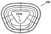
FIG. 40 is a head view of another embodiment of a cradle of a nasal mask;
FIG. 41 is a bottom view of the bracket shown in FIG. 40;
FIG. 42 is a top view of one embodiment of a pad configured to be coupled to the bracket shown in FIG. 40, the pad showing CAD construction lines;
FIG. 43 is a rear view of the pad shown in FIG. 42, the pad showing CAD construction lines.
Detailed Description
Two main embodiments are depicted in the drawings. Although some features and/or portions of the various embodiments are the same, some portions and/or components are different. For example, while FIG. 1 illustrates one embodiment of the elbow assembly 60 of the present invention, FIGS. 6a-6b illustrate an alternative assembly of the elbow assembly 60, other differences will be described below. Furthermore, several alternatives regarding the different parts and/or components will be described below and these alternatives should be considered as additional preferred embodiments of the present invention.
As shown in fig. 1-4, a nasal mask 10 according to a preferred embodiment of the present invention includes a frame 20 and a cushion 40, preferably the cushion 40 is detachably connected to the frame 20, optionally: the liner 40 may be permanently attached to the support 20 using co-molding or over-molding techniques, glue, or mechanical fastening. A swivel elbow assembly 60 and a headgear assembly 80 may be connected to the support 20. Figure 1 shows a nasal mask 10 as it would normally be when it is in position to be fitted to a person's head. Of course, for ease of understanding, FIG. 1 is shown slightly away from the head, or "floating". Fig. 1b shows the headgear 80 laid flat with the support 20 removed. Fig. 2 shows a left side view, fig. 3 shows a front view, and fig. 4 shows a top view of the mask assembly 10. In fig. 2-4, the rear portion of the headgear assembly 80 is removed for clarity.
Mask support
As shown in fig. 5, the support 20 includes an elongated body 22, the elongated body 22 having a central bore 24 for connection to the swivel elbow assembly 60. Fig. 5a is a top view of the stand 20, wherein the stand 20 includes a main body 20a designed to cooperate with the cushion 40 and a pair of side stand assemblies 20b, wherein the side stand assemblies 20b are preferably integrally formed with the main body 20a of the stand 20. Figure 5a shows a preferred case where both side bracket assemblies have the same structure. The main body 20a and side frame assembly 20b are designed to have a degree of curvature that generally conforms to the contours of the face on either side of the patient's nose. According to one embodiment of the invention, the curvature smoothly transitions from two side members having an included angle of 120, with the side frame members 20b generally parallel to the cheek portions in order to prevent contact of the body 20a with the patient's nose near the nose and away from the patient's face when the cushion 40 is in place. Since contact is not desired at that portion, a distance is maintained between each side bracket 20b and the patient's cheek. However, if desired, the side stand assembly 20b may be configured to include a comfortable structure, such as a cushion structure that engages the cheek regions of the patient. Such pads may have the advantage of helping to support the cheeks when pressure is applied in the treatment mode.
Based on the curved design and other features of brace 20, mask assembly 10 may be formed with center of gravity CG1 (FIG. 5b) closer to the patient's face. Likewise, rotational torque or moment in the vertical plane, for example due to the weight of the mask assembly, may be reduced. For example, when the patient is seated upright as shown in fig. 5b, the weight of mask assembly 10 can create a torque about axis A (into the paper) that is transverse in the horizontal plane to the patient's nose. The torque is capable of generating a force tending to rotate mask assembly 10 in the direction of arrow B along axis a, which is generally disposed along the upper lip region of the cushion, which may cause discomfort to the patient along the upper lip region or/and reduce the seal around the underbody region and/or cheeks. In particular, the center of gravity CG1, which is located close to the face, can produce a smaller torque than a mask with center of gravity CG2, where CG2 is further away from the face. This is because the distances d1, d2 between the centers of gravity CG1, CG2 and the face define the lever used to measure the torque (force x lever distance). Accordingly, if the force or lever moment is reduced, the torque can be reduced. Similar torque is also produced when the patient is lying on his side. The torque is affected by the geometry of the bend, including characteristics such as length and height relative to the liner. It is desirable to minimize the effective length of the lever of the assembly, depending on the configuration of the elbow, among other things.
Factors that help reduce the distance between the mask assembly center of gravity and the face include: the design of the gasket 40, the design of the bracket 20, and the design of the elbow assembly 60. Another source of torque is the connection of the elbow assembly to the gas delivery tube 60, which may affect the firmness of the mask. In practice, the gas delivery tube may apply a pressure to the elbow assembly 60, which in turn may create a torque tending to move the mask assembly relative to the patient. The amount of torque applied to the patient caused by the connection between the elbow assembly and the gas delivery tube may be reduced by employing an elbow assembly 60 as described below and described with respect to figures 16a-19 c-2. In short, the lever arm of the elbow assembly can be effectively reduced because it is designed to be directly connected to the gas delivery tube 310 (FIG. 26) without an intermediate swivel connection 300 (FIGS. 6b and 23) between the elbow assembly and the gas delivery tube 310, as is commonly used in some prior art applications. Alternatively, the case is: a swivel connection may be incorporated in the tube. In this way, one degree of rotational freedom can be increased without increasing the undesirable torque. And because the cushion 40 is designed to dissipate pressure at least along the lip and cheek portions of the cushion 40, the likelihood and tendency to rotate in a vertical plane is further reduced. And each cheek region of the cushion 40 forms a relatively large contact pressure receiving surface which extends in the vertical direction and widens in the horizontal direction. As such, the cushion 40 resists rotation in either the vertical or horizontal plane, at least in the cheek regions, which helps to maintain the cushion 40 in a secure position on the patient. More details regarding the gasket 40 will be described below in connection with fig. 24 a-25I. Referring to fig. 5c, the holder 20 includes a generally trapezoidal channel 26 connected to the cushion 40, the channel 26 including an inner wall 28, an outer wall 30, and a channel bottom 32. As will be described in further detail below with respect to trench 26.
Fig. 6a shows a bracket 20 and elbow assembly 60 that differs slightly from the bracket 20 and elbow assembly 60 shown in fig. 1-5 c. Although the primary difference between the embodiments is the elbow 60, there are differences between the bracket 20, the cushion 40, etc., which can be readily seen and understood by comparison between the various figures or by reference to the following description of the various parts. Like parts are denoted by like reference numerals.
In Figs. 6a and 6b, elbow assembly 60 is connected to mask 20 with a C-clip 23 that is telescoped to fit within a circumferential groove 25, groove 25 being disposed on a portion of elbow assembly 60, elbow assembly 60 passing through an ULTRA similar to ResMed One mechanism employed in the mask is to penetrate into
 cradle 20, as described in U.S. patent application No. 09/594775(Drew et al). Figure 6b shows an exploded view of the cushion 40, the bracket 20, the elbow assembly 60 and the gas delivery tube. The C-clip 23 has a surface that engages the inner surface of the holder 20 to prevent unwanted removal of the elbow 60 from the holder 20. In addition, elbow 60 may include one or more vents 61 to atmosphere, for example, for venting exhaled carbon dioxide gas. The vent 61 is constructed to enable therapeutic pressureCan be retained in the nasal cavity. The vent 61 may be covered by a cover assembly 65, the cover assembly 65 resiliently and removably clipping onto an exterior of the elbow assembly 60. The exhaust port 61 in fig. 6a is visible through the transparent cover assembly 65. Details regarding the boot assembly 65 and C-clip are described in ResMed U.S. patent application Ser. Nos. 09/502,745 and 09/594,775 or in PCT application Ser. No. PCTAU00/00097(WO00/78384), the entire contents of which are incorporated herein by reference.
As shown in fig. 6a, the inner wall 28 of the channel 26 preferably extends a distance away from the holder 20 that is greater than the distance that the outer wall 30 extends away from the holder 20. Fig. 5c and 32d also show that the inner wall 28 extends a greater distance from the support 20 than the outer wall 30 extends from the support 20. As shown in FIG. 32d, the thickness of the inner wall 28 is in the range of about 1-2mm, preferably 1.4mm, the thickness of the outer wall 30 is in the range of about 1-2mm, preferably 1.4mm, and the distance between the tops of the inner and outer walls 28, 30 is in the range of 0.5-10mm, preferably 2 mm. Furthermore, the width of the groove 26 between the vertical faces of the opposing inner and outer walls 28, 30 as shown in FIG. 32d is 2-10mm, preferably 5 mm.
By adopting such a relative distance between the inner wall 28 and the outer wall 30, the connection between the cushion 40 and the holder 20 is made easier. Because the cushion and mask support are moved together, the inner wall 20 provides a visual and/or tactile signal that adjusts the cushion. And then facilitates the continuation of the kneading process by guiding the side walls or intermediate portion 225 of the liner 40 into the grooves 26 (fig. 24e and 27a), as will be more fully described in connection with fig. 27a-29d and 32a-1-32 c-2. The shape of the groove 26 is chosen, for example, as a general trapezoid as shown in fig. 5c, in order to obtain a guide for correctly positioning the pad with respect to the groove 26 without additional guides, the groove 26 having a more symmetrical shape, for example, an equilateral triangle, a circle, a square or a rectangle, for said purpose. Of course, the liner trench 26 may take any of these shapes.
As shown in fig. 5c and 6a, the holder 20 includes a locking clip receiver assembly 34 on each side of the holder 20, the receiver assemblies 34 being adapted to be coupled to a locking clip 82 (fig. 9a and 10a) of a respective headgear assembly 80, each locking clip receiver assembly 34 including an engagement surface 35 (fig. 5c), an intermediate support aperture 36, and two locking apertures 38 on opposite sides of the intermediate support aperture 36. The intermediate support holes 36 and the locking holes 38 have a generally rectangular cross-section. Each locking aperture 38 includes a locking flange 39 (fig. 7) thereon, the flange 39 being adapted to engage a respective locking tab 116 (fig. 9a and 9b) of a locking clip 82, as will be described below. The channel 38 may provide an aperture 71 (fig. 10a) in the outer wall of the holder 20, which aperture 71 may be in addition to or in place of the locking flange 39 (fig. 7). The hole 71 at the bottom of the holder 20 can be seen in fig. 5 a. While in figure 4 there is shown an aperture 71 from the top of the holder 20. The holes 71 do not have to penetrate the side walls of the holder 20.
Head frame assembly
FIG. 1b illustrates a headgear assembly 80 according to one embodiment of the present invention, in FIG. 1b, the headgear assembly is shown in a flat-laid condition.
Band and yoke
Referring to fig. 1-4, the headgear assembly 80 includes a pair of anterior straps 84, the left and right anterior straps 84 preferably being arranged in mirror image positions with respect to each other. Each front belt 84 is generally "Y" shaped and has a front belt end 86, a top belt end 88 and a rear belt end 90 that are integrally formed or otherwise attached to one another by mechanical fastening or the like. The belt is made of laminated fabric or foam. One commercially available material is "Breath-o-Prene" TM manufactured by Accumed, USA. The strap may be secured to the bracket 20 by using a hook and loop material such as Velcro (trade name), or the strap may be secured to the bracket 20 using a locking clip 82, so that the strap need not include hook and loop fasteners, as will be described in more detail below. As shown in fig. 1-3 and 8, a yoke 92 is attached to each front belt 84. Each yoke 92 has the same general shape as the corresponding front belt 84 and has a front end 94, a top end 96 and a rear end 98. Each yoke 92 is made of a somewhat rigid material, such as plastic, and has a thickness in the range of 0.3-2.0mm, with a preferred thickness of 1 mm. Examples of plastics include nylon 11 and polypropylene. The yoke 92 is attached to the respective front belt 84 by adhesive, stitching, or other known mechanical attachment means. The belt and yoke arrangement may have different flexibility in different directions, for example stiff in a first direction (e.g. to resist deformation by gravity of a swivel elbow, associated conduit or the like), but flexible in a direction generally perpendicular to the first direction. The relatively stiff yoke helps to keep the support and cushion in place on the user once the mask is worn on the patient's head. Although having the same general shape as the front belt 84, the top and back ends 96, 98 do not generally extend to the top and back belt ends 88, 90 of the front belt 84 in the depicted embodiment. In yet another embodiment, the top end 96 may extend along the entire length of the top belt end 88 and be integrally or one-piece formed with a link 128 (fig. 1), the yoke 92 being narrower than the front belt 84 so that when they are brought together, the softer material of the front belt 84 may extend beyond the more rigid material of the yoke 92 to prevent or at least reduce user contact with the more rigid material of the yoke 92, which contact may cause irritation or discomfort. Although the belt and associated yoke are of a multi-layer construction, such as a two-layer construction, the belt 84 and yoke 92 may be formed from a single material, so long as the patient feels comfortable and maintains suitable stiffness.
The yoke 92 may increase the stiffness of the belt 84 in certain planes and orientations. This helps to stabilize the mask assembly 10 on the patient's head during use. The yoke and belt assembly may have different stiffnesses in other planes and directions. For example, the straps and yoke should be resistant to bending or curling inwardly or outwardly from the patient's face. Generally, the belt 84 and yoke 92 should be able to maintain their position relative to the patient's head when the belt 84 and yoke 92 are attached to the support frame 20. Furthermore, the support frame 20 does not have to provide a forehead support assembly, which further increases patient comfort by reducing the obstruction to the patient's view as compared to masks with forehead supports. Of course, the forehead support described above may be equipped if additional stability or comfort is desired. Mask support 20 also need not be equipped with a chin strap, but could be equipped with a chin strap if additional stability or comfort is desired. In addition, the band 84 and yoke 92 are selected to avoid interfering with the patient's view, except that the forehead support is removed. Particularly when installed, the forward end 94 of each yoke 92 is connected to the support 20 beneath the patient's eye and preferably extends along a curved arc and rests across the cheek regions, with the top end 88 of each strap 84 and the top end 96 of each yoke extending outwardly from the Y-shaped intersection along the temple region of the patient's head. The rear end 98 of the yoke 92 and the rear end 90 of the band 84 are bent downwardly and around the ears for attachment to a rear band assembly 138, as will be described in greater detail below. Due to the stiffness of the yoke 92, it is preferred that the belt 84 maintain a predetermined shape. On the other hand, the yoke 92 and the belt 84 also have some flexibility so as to be adjustable to some extent to accommodate physiological differences in the patient. The thickness of the yoke 92 along its sides may also be varied to change the flexibility characteristics, e.g., thicker regions may be stiffer.
As shown in fig. 8, each yoke 92 has a mounting flange 100 at the front end 94. The mounting flange 100 has a hole or key hole 101 leading to a hole 103, see fig. 8 a. The two semi-annular flanges 102 are separated from each other by a groove 104. The radially inner surface of the semi-annular flange 102 forms a central aperture 103. The yoke 92 also has a resilient tab 106 located at the rear of the mounting flange 100, the resilient tab 106 having a front portion connected to the yoke 92 and a rear portion spaced a distance 107 from the yoke 92 so as to flex relative to the yoke 92 when pressure is applied to the resilient tab 106. The resilient projections 106 preferably have a plurality of teeth 108 located on an arc about the axis of a mounting flange 100. The resilient tab 106 also has a textured surface 110 (fig. 8) or a raised detent 110a (fig. 8a) at its free end to assist the user in locating, engaging and manipulating the resilient tab 106. Fig. 8a is an enlarged view of the right yoke 92 and belt 84 to better show the details of the yoke 92, and the upper view also shows the manner in which the yoke 92 is stitched to the belt 84. Other securing mechanisms such as locks or friction may also be used.
Locking clip
Locking clip 82 is adjustably attached to each of the mounting flanges 100. As shown in fig. 9a and 9b, each locking clip 82 includes a main body 112. Two resilient arms 114 are attached to opposite sides of the main body 112 and extend outwardly from the main body in a generally parallel manner. A hook 116 is attached to the free end of each spring arm 114.
As shown in fig. 10a, the clips 82 can be inserted into releasable engagement with the locking clip engagement receivers 34 of the bracket 20. in fig. 10a, only one clip 82 is shown and is not assembled with the yoke 92. Each latch hook 116 is received in a respective one of the channels 38 of the bracket (fig. 5 c). In fig. 10a, the distal end of the latch hook 116 is shown in a position prior to bending outwardly into each receiver on the groove 38. Fig. 4 shows the hook end in the engaged position within receiver 71. Of course, the clip 82 or at least the catch 116 thereon can be formed on the bracket 20 and the groove 38 or at least the receiver 71 can be formed on the belt and/or yoke.
Fig. 4 and 10a also show that the locking clip 82a preferably forms a substantially continuous surface with the outer surface of the holder 20, which surface is continuous and uninterrupted. Preferably, the locking clip 82 is as wide as the bracket 20 at each end, which makes patient contact positioning easier. The resilient arms 114 are designed to be resilient in the plane of the locking clip body, which further improves the ease of attachment and detachment of the locking clip 82. This arrangement improves the efficiency of the release mechanism. The locking clip 82 can be easily positioned and operated by the thumb and one opposing finger of the patient. Also, because of their increased size, the locking clips 82 can be operated with minimal flexibility by the patient. Further, the locking clip 82 is attached to the belt 84/yoke 92 so that length adjustment between the locking clip 82 and the belt 84/yoke 92 is not necessary.
The locking clip 82 includes a retaining flange 118 (fig. 9b) extending laterally outward from the body 112, the retaining flange 118 having a central socket 119 extending along an axis of the retaining flange 118 and two retaining tabs 120 located on opposite sides of the central socket 119, the two retaining tabs 120 extending laterally from the central socket 119. Fig. 10b-d show further details of the locking clip 82 shown in fig. 10a, which are similar to features in fig. 9a and 9 b. Although the locking clip 82 is shown as being separate from the yoke 92, it will be appreciated that the clip and yoke 92 may be formed as a single piece if relative movement and/or removal between the two is not necessary. The clip 82 and the bracket 20 may be formed as an integral unit and the clip portion can be attached to the yoke.
The retention flange 118 is sized and shaped so that the retention projection 120 mates with the slot 104 and the retention flange 118 is axially inserted into the mounting flange 100 of the yoke 92. The intermediate socket 119 is sized to have a high tolerance with respect to the intermediate hole 103 so that the locking clip 82 and the yoke 92 are rotatably supported with respect to each other. Once the retaining flange 118 has been inserted into the mounting flange 100, the locking clip 82 can be rotated relative to the yoke 92 so that the retaining tabs 120 engage the inner surface of the flange 102, thereby axially locking the mounting clip 82 to the yoke 92, the locking clip 82 being shown in various positions relative to the yoke 92 in FIGS. 10 e-g. In fig. 10e, the projection 120 of the clip 82 has been inserted through the aperture of the yoke 92 and the clip 82 has been rotated slightly in the direction of arrow a so that the upper surface of the projection 120 is in sealing engagement with the inner surface of the semi-annular portion 102. When the clip 82 is attached such that the flexible arms 114 are at an approximately 90 degree position relative to the front end 94 of the yoke 92, the clip 82 is able to separate from the yoke 92. In the embodiment described, the separation can take place in two positions, and both positions are chosen so as to ensure that separation does not occur during normal use of the mask; otherwise the clip 82 can be freely removed from the yoke 92. Fig. 10f and 10g show the clip 82 in different positions relative to the yoke 92.
As seen in fig. 9b and 10b, the locking clip also has a plurality of teeth 122 on an arc near an axis of the retaining flange 118. The teeth 122 are configured and arranged to engage the teeth 108 on the resilient projection 106. Once the resilient tab 106 is depressed to lower the teeth 108, the locking clip 82 is able to rotate to a desired position relative to the yoke 92. The resilient projections 106 may then be released to engage the teeth 108 with the teeth 122 in a desired position (within one pitch) and rotatably lock the locking clip 82 relative to the yoke 92. According to one embodiment, the teeth 108 and 122 may be configured such that when a predetermined torque is applied to the locking clip 82, the teeth 122 will automatically apply downward pressure to the teeth 108 and resilient projections 106 to allow the locking clip 82 to rotate until the torque is removed and the teeth 108 reengage the teeth 102. The locking clip 82 is thus capable of rotational adjustment relative to the yoke 92 through an angular range of about 50-100, preferably 75, depending on the engagement position between the teeth 108 and 122. By varying the number and position of the teeth 108 and 122, the rotational adjustment angle that can be achieved can be varied according to the desired angle. The range of adjustment angles reflects the position of the associated cushion required for the face. The rotational adjustment of the toothed system as described above allows the patient to make adjustments easily and to accommodate a large range of facial changes from patient to patient over a large range of positions. For example, the patient may adjust both locking clips 82 to have the same angle relative to the yoke 92. Alternative situations are: the patient can adjust the locking clip 82 so that the locking clip has different respective angles relative to the yoke 92. The tooth system allows the patient to easily set and reset the desired angle for each locking clip 82. For example, the tooth system may allow relative movement between each locking clip and its respective yoke at, for example, five positions, which accommodates most facial shapes. Of course, more or less than five positions may be used, depending on the particular application. Moreover, once a particular desired angle of each locking clip 82 relative to the yoke 92 is determined, the mask system may include a non-adjustable clip means for fixing the rotational position of the locking clip relative to the yoke 92. The teeth are large enough so that the patient can easily determine the relative position of the locking clip with respect to the yoke.
In addition, the resilient tab 106 is configured and arranged such that the patient cannot depress the resilient tab 106 at will, such as by rotating the locking clip/yoke, to cause relative movement of the locking clip 82 with respect to the yoke 92 during sleep. For example, as shown in FIGS. 10e-10g and FIG. 36 (a different embodiment), the locking clip 82 extends further outward than the resilient tab 106. That is, the resilient projection 106 is at a position lower than the outer edge of the locking clip 92. Thus, the positioning of the locking clip 82 relative to the resilient projection 106 prevents inadvertent actuation of the resilient projection 106. And the resilient tab 106 is coupled to the yoke 92 such that the yoke 92 can flex inwardly or outwardly from the resilient tab 106 without disengaging the teeth 108 of the resilient tab 106 from the teeth 122 of the locking clip 82.
Alternative adjustment assemblies may be achieved by simply reversing some or all of the sub-assemblies. For example, the intermediate socket 119 may be located on the yoke 92 and its corresponding yoke intermediate hole 103 may be located on the locking clip 82. In a similar manner, each subassembly and its corresponding parts may be reversed. Alternatively, the yoke 92 and the locking clip 82 may be adjustably connected by a screw and clamp arrangement. For example, one portion may be separate from the yoke and the frame, and the screws or clamps can be used to selectively connect the yoke and the clip 82 at any number of desired locations. In addition, the central aperture 103 may be formed in any manner that allows for the detachment and attachment between the yoke and the clip. An alternative system that allows a fixed angle yoke with respect to the locking clip may also be used.
Locking clip 82 also includes a central prop projection 124, which prop projection 124 extends outwardly from body 112 and is between spring arms 114 and generally parallel to spring arms 114. The intermediate projection 124 is configured to mate with the intermediate support hole 36 to allow for little rotation, rocking or co-movement between the locking clip 82 and the locking clip receiving assembly 34 when the intermediate projection 124 is inserted into the intermediate support hole 36. The intermediate support projection 124 is longer than the arm 114 to facilitate alignment into the stent. The locking clip 82 also has an engagement surface 125 that engages the engagement surface 35 (fig. 5c), the engagement surface 125 providing additional support to the locking clip 82 when the locking clip 82 is inserted into the locking clip receiving assembly 34. The shackle 116 and/or intermediate bracing projection 124 may have a tapered width and/or thickness for easier insertion into the holes 36, 38. Also, the shackle 116 and/or the intermediate support protrusion 124 may have rounded or conformable edges for easier insertion into the holes 36, 38. In addition, the middle support protrusion 124 may have a groove that is combined with a protrusion portion provided on the middle support hole 36 to make it easier to insert the middle support protrusion 124 into the middle support hole 36. Alternatively, the middle support protrusion 124 may have a protrusion that may be engaged with a groove provided on the middle support hole 36.
When the locking clip 82 is inserted into the locking clip receiving assembly 34, and when the shackle 116 is inserted into the receiver 71 (FIG. 4) or over the locking flange 39 (FIG. 7), the spring arms 114 are forced toward one another. Once the catch 116 passes over the locking ledge 39 or the receiver 71, the resilient arms 114 can spring outwardly to provide a locking engagement between the catch 116 and the locking ledge 39 and/or the receiver 71. Sufficient space is provided in the latch bore 38 to allow the necessary movement of the latch hook 116 to clear the latch ledge 39.
In this manner, each of the left and right front belt assemblies, including the front belt 84, yoke 92 and locking clip 82, can be attached to the bracket 20, and the yoke 92 and front belt 84 can be rotationally adjusted relative to the bracket 20 within an angular range of 50-100, preferably 75.
In a preferred embodiment, the locking clip 82 is a unitary piece of plastic formed by injection molding. Examples of plastics include nylon, acetal, and polypropylene. In one embodiment, the retention tabs 120 are also formed by a mold shot that leaves the holes 116 through along the body 112 of the locking clip 82 during the molding shot, so that the lower surface of the retention tabs 110 and the body 112 are separated.
Magnetic interconnection
Fig. 33-37 illustrate an alternative embodiment of a removable connection between the holder 420 and the headgear assembly 480. In particular, the bracket 420 and yoke 492 are configured such that the yoke 492 can be magnetically coupled to the bracket 420.
As shown in fig. 33, the stand comprises a main body 420a and a pair of side stand assemblies 420 b. Similar to the embodiment having the bracket 20, the main body 420a is also configured to be detachably coupled with the cushion 40. Each side bracket assembly 420b includes a first connection portion 434 for connecting with a second connection portion 435 provided by a yoke 492 on a headgear assembly 480. In the illustrated embodiment, the first connection portion 434 includes a retaining structure 418 that extends outwardly from the side bracket assembly 420 b. The retaining structure 418 is configured to retain a magnet 419. In one embodiment, the magnet 419 is constructed of neodymium and has a cylindrical shape with a diameter of 6.35 millimeters and a thickness of 6.35 millimeters. However, the retaining structure 418 may be configured to retain any size and shape of magnet. Further, the outer edge of each side bracket assembly 420b includes a plurality of arcuate rows of teeth 422.
As shown in FIGS. 34 and 35, the yoke 492 on each headgear assembly 480 has a similar configuration to the yoke 92 on the headgear assembly 80. In particular, each yoke 492 contains a second connecting portion 435 having a mounting flange 400 at its forward end 494. The mounting flange 400 has a hole or keyhole 401 leading to a hole 403. The two semi-annular flanges 402 are separated from each other by a groove 404. The radially inner surface of the semi-annular flange 402 forms a central aperture 403. The yoke 492 also has a resilient tab 406 at the rear of the mounting flange 400, the resilient tab 406 being connected at a front to the yoke 492 and at a rear spaced from the yoke 492 by a distance 407 so as to flex relative to the yoke 492 when pressure is applied to the resilient tab 406. The resilient projections 406 preferably have a plurality of teeth 408 located on an arc about the axis of a mounting flange 400. The resilient projection 406 also has a raised detent 410 at its free end to assist the user in locating, engaging and manipulating the resilient projection 106.
In contrast to the yoke 92, the yoke 492 comprises a ferrous metal disc 412 secured to the hole 403. In one embodiment, the metal disk 412 is a steel washer having a diameter of 14mm and a thickness of 1 mm. However, the metal disc 412 may have any suitable size and shape that fits into the hole 403 in the yoke 492. Also, a suitably sized and shaped magnet may be used in place of the metal plate 412.
As shown in fig. 36 and 37, the first connecting portion 434 on the bracket 420 and the second connecting portion 435 on the yoke 492 are engaged so that the magnet 419 and the metal plate 412 can be magnetically engaged together. In particular, the magnet 419 is axially inserted into the central bore 403 such that the magnet 419 is adjacent to or engages the metal disk 412, which allows magnetic attraction between the magnet 419 and the metal disk 412 to axially retain the yoke 492 to the bracket 420. As discussed above, replacing the metal plate 412 with a magnet may increase the magnetic attraction between the yoke 492 and the bracket 420. The retaining structure 418 and the aperture 403 are sized with a high degree of dimensional tolerance therebetween so that the bracket 420 and the yoke 492 can be rotatably supported relative to one another.
In addition, the teeth 422 on the bracket 420 are configured and arranged to engage the gears 408 on the resilient projections 406 when the bracket 420 magnetically engages the yoke 492. Once the resilient projection 406 is depressed to lower the teeth 108, the yoke 492 is able to rotate to a desired position relative to the bracket 420. The resilient projection 406 may then be released to engage the teeth 408 with the teeth 422 in a desired position (within one pitch) and rotationally lock the bracket 420 relative to the yoke 92. According to one embodiment, the teeth 408 and 422 may be configured such that when a predetermined torque is applied to the yoke 492, the teeth 422 will automatically apply downward pressure to the teeth 408 and resilient projections 406 to allow the yoke 492 to rotate until the torque is removed and the teeth 408 re-engage the teeth 422. The yoke 492 is thus rotatably adjustable relative to the support 420 through an angular range of about 50-100, preferably 75, depending upon the engagement position between the teeth 408 and 422.
The magnets 419 on each side bracket assembly 420b are oriented such that an incorrect connection (e.g., the yoke 492 on the left side being placed on the side bracket assembly 420b on the right side) is identified by repulsion of the magnetic forces. In particular, the magnet 419 on one side bracket assembly 420b is oriented so that the magnet 419 can only magnetically couple with one of the yokes 492, and the magnet on the other side bracket assembly is also oriented so that it can only magnetically couple with the other side of the yoke 492. Thus, a sensory determination of proper connection between the holder 420 and the headgear assembly 480 is obtained by proper mating magnetic attraction between the yoke 492 and the side holder assembly 420 b. This configuration may ensure proper mounting between the headgear assembly 480 and the frame 420. Moreover, this configuration allows the mount 420 to be easily engaged with the headgear assembly 480 even in the dark, since the magnet 419 will automatically position itself in the correct position relative to the metal plate 412. The head assembly 480 can be easily detached from the bracket 420 by applying a suitable detachment force that is greater than the magnetic attraction between the magnet 419 and the metal plate 412.
Alternatively, the first connection portion 434 on the bracket 420 may be provided with a ferrous metal disc and the second connection portion 435 on the yoke 492 may be provided with a magnet.
Tape
Each front strap 84 includes a ladder-shaped buckle 128 connected to the top strap 88 for connecting the top strap 88 to a top strap 140 of the cross strap 138. See fig. 1-3 and 11. The buckle 128 may be attached to the top strap 88 by adhesive, stitching, and/or other known methods, such as being integral with the strap. In the embodiment shown in FIG. 11, the buckle 128 includes a plurality of holes 130 evenly distributed in a square shape on a coupling projection 132, the holes 130 enabling the strap to be sewn to the top strap 88. The strap also includes a cross-piece 134 and a cross-piece 136 about which the top strap 140 can be threaded in a known manner. The top strap 140 is thus wrapped around the cross-bar 136 with the free end of the top strap 140 between the cross-bar 134 and the remainder of the top strap 140. Thus, when tension is applied between the buckle 128 and the top strap 140, the free end of the top strap is held between the cross bar 134 and the remainder of the top strap 140 by friction, so that the connection between the buckle 128 and the top strap 140 is self-controlled under tension. A single cross strap buckle may also be used when engaging a belt loop and securing the belt in place. Other connecting assemblies known in the art may of course be used instead of buckles.
As shown in FIG. 12, cross-ties 138 have a generally elongated shape in a relaxed state, and two top straps 140 extend upwardly from a transverse strap 142 having a distal end 144. To place the cross strap 138 in a wearable configuration, two top straps 140 are threaded through a cross buckle 146 so they are held in a crossed position. See fig. 13 and 14. In this manner, the left top strap 140 of the cross strap 138 is cross-connected with the buckle 128 of the right top strap 88, while the right top strap 140 of the cross strap 138 is cross-connected with the buckle 128 of the left top strap 88. This crossing of the straps can help to position headgear assembly 80 and nasal mask 10 in a desired adjustable position on the user. The band 148 can press against the free end of the respective strap. See fig. 15. In one form of the invention, an elongate strap is provided which can then be cut to a length appropriate to the user.
Similar to the buckle 128 and the top strap 88, a buckle 150 (fig. 1) may be attached to the cross-strap end 144 to facilitate connection of the cross-strap end 144 with the rear strap end 90 on each of the front straps 84.
Rotary elbow assembly
The swivel elbow assembly 60 shown in fig. 6a may be used with the ULTRA (r) currently used in ResMed corporation As in the mask, an internal C-clip assembly is used as described above. The
 elbow assembly 60 of fig. 6a is intended for connection to a connecting tube 300 (fig. 23). The connecting tube 300 is provided between the elbow assembly 60 and the gas delivery tube 310 (fig. 26).
Alternatively, the elbow assembly may be constructed in accordance with the configurations shown in FIGS. 1-4 and 16-22. Such an elbow assembly 60 may include a swivel elbow 160 and a vent cover 180. A swivel elbow 160 is rotatably connected to the bracket 20.
In an alternative form of the invention, an additional rotating member is attached to the end of tube 310 as shown in FIG. 6 b.
As shown in fig. 16a-19c-2, the swivel elbow 160 includes an inlet passage 162 and an outlet passage 164. Air tube 310 (fig. 26) is preferably connected directly to stem 166 of swivel elbow assembly 160 (without connection tube 300) to provide compressed breathing air or gas for breathing by the patient from a compressed supply source and provided to the patient through air tube 310, air inlet passageway 162 and internal cushion 40.
The exhaust passage 164 is separated from the intake passage 162 by, for example, a partition plate 161, and the partition plate 161 is disposed inside the elbow 160. See fig. 18 and 19 a-1. In the illustrated embodiment, the baffle 161 has a generally planar configuration. However, the partition 161 may have a curved configuration or other suitable configuration to separate the vent 164 from the air intake passage 162. The directions of intake passage 162 and exhaust passage 164 are selected so that the incoming gas, represented by directional arrows in intake passage 162, is less likely to directly stagnate the flow of gas being exhausted along exhaust passage 164. Further, since the baffle 161 forces the incoming gas through a tortuous path, the gas entering the elbow 160 has less of a possibility of flowing directly into the exhaust passage 164, for example, rotating 180 degrees before being able to exit the gas through the exhaust passage 164.
The elbow 160 includes an end portion 169 adapted to engage the aperture 24 provided in the frame 20 and is used to provide air to the nasal cavity formed by the frame 20 and cushion. The baffle 161 terminates just within the end portion 169 of the elbow. A flexible quick release mechanism includes a collar 173 and a skirt 170. The collar 173 includes a conventional T-shaped component that surrounds the end 169 of the elbow 160 as shown in fig. 16 b. Preferably, the end 169 of the elbow 160 extends beyond the collar 173 to improve alignment when assembled to the holder 20. As shown in fig. 18, the collar 173 is concentric with and separated from the end portion 169 to form a receiving space 183 between the collar 173 and the end portion 193. The skirt 170 is preferably integrally formed with the elbow 160 and is connected to the lower leg of the T-shaped collar 173. Two channels 167 are provided between the collar 173 and the skirt 170. A portion 167a of the channel 167 allows the lower leg portion of the T-shaped collar 173 to be bendable relative to the skirt 170. A portion 167b of the groove 167 allows the transverse portion of the T-shaped collar 173 to be bendable inwardly or outwardly relative to the end 169 of the elbow 160.
Fig. 19a-1-19c-2 show successive views of the connection of the elbow 160 and the bracket 20. Fig. 19a-1-19a-2 show a cross-sectional view of elbow 160 prior to attachment to mask support 20. Fig. 19b-1-19b-2 show the elbow 160 and bracket 20 in a near connected position, and fig. 19c-1-19c-2 show the elbow 160 and bracket 20 in a fully connected position.
The bracket 21 includes a flange 21 disposed at one end of a wall 25, the wall 25 forming an aperture 24. Fig. 5 and 5a show the flange 21, however, the embodiment of fig. 6a does not show or include one such flange since a different elbow assembly 160 is used. When the flange 21 is inserted into the space 183, it engages with the projections 181 formed on the inner surface of the collar 173. In the present embodiment, only two protruding members 181 are provided. The projection 181 is tapered so that engagement with the flange 21 will cause each end of the lateral portion of the T-shaped collar 173 to flex outwardly (19b-1-19b-2) until the flange is aligned and received in the groove 167b (19c-1-19 c-2). In this state, with the elbow 160 secured to the bracket 20, the collar 173 returns to its unflexed state. The flange 21 rests partially on the receptacle 165 disposed in the space 183.
During the click-action connection between elbow 160 and bracket 20, the engagement between collar 173 and flange 21 causes an audible click or audible cue that is beneficial in signaling to the user that elbow 160 is securely connected to bracket 20.
To release the elbow 160 from the bracket 20, the portions 185 on each side of the collar 173 are bent inwardly toward each other in order to project the projections 181 radially outwardly to allow passage of the flange 21. In this manner, the elbow 160 can be quickly and easily removed from the mount 20 without entering the interior of the nasal cavity. This occurs when the elbow is connected with a C-clip (fig. 6 b). As shown in FIG. 16b, one preferred form of elbow 160 includes a textured projection 185 for assisting the user in locating the release point. The distance between the opposing textured portions 185, i.e., the diameter of the collar 173, is 35-45mm, and preferably 40 mm.
The elbow 160 is also adapted to connect directly to the gas delivery tube 310 (fig. 26) without the connector 300 (see fig. 1) as shown in fig. 23. Figure 6b shows the connection 300 between the elbow and the gas delivery tube 310. The elimination of the connector 300 is advantageous because the effective lever length of the elbow and connector 300 combination can increase the level of undesirable torque applied to the support or mask 10 relative to the patient's head/face. By eliminating the need for the attachment member 300, the effective length of the lever arm can be reduced, which results in less torque being applied to the mask assembly, which results in increased stability. With increased stability, patient comfort is improved and compliance is increased.
In the connected state, the inner surface of the wall 25 of the bracket 20 is in sealing engagement with the outer surface of the end portion 169 of the conduit as shown in figures 19a-1-19 c-2. These surfaces engage each other a distance of about 1-10mm, preferably 6mm, which will aid in sealing and provide a stable connection between the elbow 160 and the bracket 20. As shown in fig. 19c-1-19c-2, a portion of arm 25 extends into mask 20, further increasing the contact area between elbow 160 and support 20. In the connected state, the end portion 173a of the ferrule 173 is in the same plane as the outer surface 20c of the holder 20, as shown in fig. 19c-1-19 c-2. The wall 25 includes a flange 25a (fig. 19c-2), said flange 25a serving to provide a stop for the insertion of the end portion 169 and to allow a controlled gap between the elbow 160 and the bracket 20. In one embodiment, the gap between the elbow 160 and the bracket 20 is minimized. In another embodiment, a seal is provided between the elbow 160 and the bracket 20 to prevent leakage.
This system enables a quick and accurate connection between the elbow 160 and the bracket 20. But also simple disassembly. Moreover, the elbow 160 is configured to allow the patient to attach and detach the elbow 160 from the support 20 with one hand. This is advantageous when the mask is removed or if the patient chooses to discontinue treatment for a period of time and resume treatment after a short period of time. The connection between elbow assembly 60 and frame 20 allows the patient to quickly remove elbow 160 from the blower gas delivery tube to hold the mask frame, cushion and headgear in place on the patient's head during a transient interruption in treatment. The aperture 24 is large enough to reduce resistance and to allow the patient to breathe smoothly since a sufficient amount of gas can be regulated through the aperture 24, and in particular, the aperture 24 has an area of at least 180mm 2. In one embodiment, the apertures 24 have a diameter range of 20-30mm and an area range of 200-600mm2, preferably in the range of 500-600mm 2. As shown, the aperture has a generally circular shape. However, the aperture may also have a non-circular shape. Alternatively, the support may have a plurality of apertures through which the elbow engages the support such that the elbow surrounds the apertures. In this regard, the mask according to one embodiment of the present invention differs from prior art mask devices that include a quick release mechanism and have a relatively narrow orifice that may cause patient discomfort, such as anxiety or claustrophobia. This discomfort may be exacerbated by increased exhaled CO2 or increased flow resistance.
Ventilation hole cover
The vent cover 180 includes a main body 182 with a lower aperture 184, a curved portion 186, and a top portion 188 for the main body 182. See fig. 20-22. While the main body 182 includes at least one vent hole 190, in a preferred embodiment, a plurality of vent holes 190 extend from the interior of the vent cover to the exterior of the vent cover. The top 188 of the vent cover 180 includes a flange or aperture 192 for engaging the pin 168 of the swivel link 160. In the illustrated embodiment, the vent cover 180 includes an aperture 192. The vent cover 180 is attached to the swivel joint 160 by passing the stem 166 of the swivel joint 160 through the lower hole 184 of the vent cover 180. The vent cover 180 is moved toward the swivel joint 160 until the pin 168 extends through the aperture 192, as shown in fig. 1. This configuration allows the vent cover 180 to remain adjacent to the elbow assembly and/or mask assembly 10 since the vent cover 180 is secured by the elbow 160 or gas delivery tube. This is convenient when the vent cover 180 is cleaned or accidentally removed, as it remains on the mask assembly and is not lost.
The bent portion 186 is mounted adjacent the swivel joint diaphragm 170 to provide a conventional air seal between the interior of the vent cover 180 and the swivel joint 160. In this manner, gas exhausted from the interior of one mask may flow through the exhaust passage 164 of the swivel joint 160, through the interior of the vent cover 180 and out to the atmosphere through the vent holes 190. Fig. 19c-1 includes an arrow B depicting the general discharge path of the gas when the vent hood is in place. An additional advantage of this arrangement is that the orientation of the vent reduces or prevents irritation to the patient's companion from the flow of air out of the mask. Fig. 1-4 illustrate the swivel connection 160 and the vent cover 180 in a connected state. The spacer 163 ensures that there is sufficient spacing between the vent cover 180 and the outer surface of the elbow 160, and since the vent cover is preferably made of a soft, resilient material, the spacer 163 is particularly helpful in preventing air gap breakage. Of course, if desired, the vent cover may be made from a plastic family member somewhat like the cover used on Ultra mirage (tm), and in addition, the vent arrangement may be replaced or supplemented by the ResMed vent assembly disclosed in U.S. patent application serial No. 09/021, 541, which is incorporated herein by reference in its entirety.
Fig. 18b-18e illustrate another embodiment of a swivel connection, generally designated by the reference numeral 360, which is adapted to be connected to the vent cover 380 shown in fig. 22b-22 e. As shown in fig. 18b, 18c, 18e, the rotary connector 360 comprises a flange 361 at the end of a wall 362, said flange 361 surrounding the outlet of the exhaust channel 364. Fig. 18d and 18e show the inlet passage 365, the outlet passage 364 and a partition 369 separating the inlet passage 365 and the outlet passage 364. As shown in fig. 18e, the partition 369 has a curved configuration. In particular, the partition 369 is generally curved downward as it extends from the inlet of the exhaust passage 365 to the outlet of the exhaust passage 365. However, the partition 369 may have a generally planar configuration similar to the partition 161 shown in FIGS. 19 a-1. Alternatively, the partition may have any other suitable structure for separating the intake passage 365 from the exhaust passage 364. As shown in fig. 22b-22e, the vent cover 380 includes a main body 382 having a lower aperture 384, a middle portion 386, and a top portion 388. While the main body 382 has a plurality of vents 390 extending from the interior of the vent cover to the exterior of the vent cover. The top 388 of the vent cover 380 has a collar 392 for engaging the flange 361 on the swivel elbow 360. The vent cover 380 is attached to the swivel elbow 360 by passing the rod 366 of the swivel connector 360 through the lower aperture 384 of the vent cover 380. The vent cover 380 is then moved toward the swivel elbow 360 until the collar 392 latches onto the flange 361 on the swivel elbow 360. The collar 392 is stretched against the flange 361 of the swivel elbow 360 and due to its resiliency grips the flange 361 tightly. In the illustrated embodiment, the collar 392 is generally circular so that the pressure exerted on the flange 361 and the wall 362 ("annular pressure") is evenly distributed. Similar to the vent cover 180 embodiment, this configuration allows the vent cover 380 to rest adjacent the swivel elbow 360 and/or mask assembly because the vent cover 380 is secured by the elbow 360 or gas delivery tube. Since the vent cover can be held in place on the elbow to cover the vent passageway without additional securing means, it can be considered to be "self-retaining". In addition, as the patient pulls the collar 392 over the flange 361, the vent cover is retained on the elbow by the annular lower hole 184, which reduces the chance of losing the vent cover if the first assembly attempt fails.
Fig. 22f shows the swivel elbow 360 and vent cover 380 in the connected position. As shown in fig. 18c and 18e, the swivel elbow 360 includes a wall 363 that ensures sufficient space between the vent cover 380 and the outer surface of the swivel elbow 360, since the vent cover is preferably made of a soft, resilient material, which is particularly helpful in preventing gas gaps caused by breakage. The vent cover 380 includes a recess 389 (fig. 22c) on the interior surface of the top 388 for engagement with the wall 363.
Mask pad
The cushion is designed to be placed on the face and to apply pressure around its perimeter while reducing or avoiding contact with pressure sensitive areas of the face. Certain parts of the face require special attention to obtain pressure balance and sealing. It would be desirable to provide a low profile mask with improved stability to improve patient comfort and reduce the forces that can rotate the mask relative to the patient's face. These characteristics and the approach taken to make a successful design are listed below.
The cushion has a face-contacting surface and a non-face contacting surface and has a wall therebetween. The non-face contacting surface of the cushion is connected to the mask support. In one form of the invention, the cushion shape of the face-contacting surface is generally trapezoidal, as shown in the various views of FIG. 24 c. In this regard, one advantage of this trapezoidal shape over prior art cushions having a generally triangular shape is that it helps to achieve a seal at a point below the nose and also does not impede flow through the patient or user's nares (i.e., the cartilage area on the side of the nose on each side of the nose and just below the nasal bone). Thus, the cushion is placed under the nasal bridge region of the patient. And, the cushion is constructed and arranged such that contact pressure in the nostril region is minimized or eliminated. The shape of the pad may vary, such as: a triangular or other non-trapezoidal shape may be used keeping in mind that the location pressure points are below the nasal bridge region and avoid clogging the nostrils. Some prior art mask cushions push against the nares, which increases the resistance to airflow to the nares. In one preferred form of the cushion, the face-contacting surface and the non-face-contacting surface of the cushion both have the same generally trapezoidal shape.
In one form of the invention, a combination of a support structure and a sealing structure is provided in the face-contacting area of the cushion. The support structure and seal structure may be configured as part of the cushion, or separate components may alternatively be employed. In the case where the support structure and the sealing structure are provided as part of a cushion, the cushion may have a single-walled, double-walled, or three-or more-walled structure. In a preferred form of the gasket, the sealing structure is provided by a thin member and the support structure is provided by a thicker bracket.
The middle and sides of the bridge of the nose are particularly sensitive to contact pressure. It is therefore important that the seal of the gasket in said area is as light as possible. Instability of the cushion may be caused by an increased pressure applied to the nasal bridge region, thus presenting an additional challenge in that region. The support (e.g., cradle 200 shown in fig. 24 a) may be designed to completely avoid contact with adjacent portions of the component on the face-contacting surface (such as membrane 205 shown in fig. 24 a), thus allowing membrane 205 to be sealed separately. Although the anchor point of the contact pressure should be avoided in the nasal bridge region, and in particular at the most sensitive point of contact with the lower part of the nasal bridge region, the seal must be maintained. The lower part of the nasal bridge region is usually located where the bony region of the bridge transitions to a portion of the nose containing more cartilage. In addition, the force applied to the face should be evenly distributed over the entire circumference of the cushion 40. One aspect of the present invention is that the facial contact pressure is controllably distributed around the face. Of course, to prevent localized pressure, the force applied to the lower portion of the nasal bridge region may be distributed outwardly along a wider region of the membrane 25, however, because the pressure may be more comfortably accommodated in the lips, and particularly the cheek regions, the force applied to the lips and cheek regions may be lighter, such as extending outwardly far beyond the width. Furthermore, while maintaining a relatively timely overall pressure distribution along the patient's face, the area or width of contact of the membrane and face in the lower nasal bridge region may be greater than the area or width of contact of the membrane and lips and cheeks, which improves comfort. With this arrangement, the patient feels that the pressure is evenly distributed over the contact area even though the pressure acting on the contact area may not be evenly distributed.
Another advantage is that the angle of the cushion relative to the patient can be varied without adversely affecting the efficacy of the seal. For example, the cushion may contact different patients at different angles based on different shapes of the patient's face, and the angle of the cushion may move relative to the face during movement while the patient sleeps.
The seal (e.g., membrane 205) includes a large effective wrap (large radius) to allow some degree of movement or wrapping of the mask relative to the patient's face and to prevent the terminal edge of the membrane from irritating the patient's face and/or nose. The seal (e.g., membrane) seals tightly against the nose by conforming to the lower portion of the bridge of the nose on either side of the nose. A compromise must be reached between a secure seal and the tightness/extensibility of the membrane through the nose. The film slit can be grooved to maximize stretch distance without edge tightness. Extensibility can also be achieved by materials, for example, soft materials and/or thin materials, for example, elastomers, silicone, polyurethane, thermoplastic elastomers, foams, and/or synthetic substances.
The seal (e.g. membrane) preferably has a thickness in the range of 0.1-2.0mm, more preferably 0.35mm of elastomer, which allows the membrane to be easily stretchable over the lower part of the bridge of the nose, the stretchability of the membrane in different regions can be varied by varying the thickness, applying stiffening structures such as ribs, or with composite structures.
Facial folds are mostly produced in the nasal folds (known as nasolabial folds) on the sides of the face or nose. The base cushion (such as the brace shown in figure 24 a) is placed as close to the side of the nose as possible. So that the gasket seals in the flattest possible area. The curved area designed to be placed in the area of the facial folds should have a radius as small as its actual radius. The membrane 205 projects further inward or downward than the edge of the cushion (e.g., the frame 225) to allow for wrapping along the outer edge on the side of the nose. This reduces the likelihood of irritation caused by rough edges and prevents the inner liner edge from becoming a source of irritation for the patient's face and/or nose.
Excessive pressure across the upper lip may be caused by the design of the cushion and vertical rotation of the mask under its own weight, or by undesirable pressure exerted on the mask, for example, due to drag of the conduit or the weight of a component attached to the mask. As mentioned above, the design of the headgear may help to reduce undesirable pressure on the lip region caused by rotation of the mask in a vertical direction under its own weight. The lip region 42 may include an incision to accommodate the bottom of the patient's septum to improve sealing and comfort, as shown in fig. 24 g. The diaphragm opening 264 should be disposed within the region 265 as shown in figure 24 c. Fig. 24a and 24b show front and rear views of the cushion 40. In an alternative embodiment, a diaphragm opening may also be provided in the base pad.
In the present embodiment, the liner 40 preferably has a generally trapezoidal shape. However, the liner 40 may also have a non-trapezoidal shape, such as a triangular shape. The cushion 40 includes a pair of cheek regions 41 for providing a seal against the folds between the cheeks and the sides of the nose; a lip region 42 for providing a seal between the underside of the patient's nose and the upper lip; and a nasal bridge region 43. The nasal bridge region 43 spans the lower portion of the bridge of the nose and the angled edges of the bridge of the nose and intersects the nasal folds formed in the cheeks and on the sides of the nose. The transition between the lip region 42 and each cheek region 41 is where the cushion 40 begins to turn from around the bottom of the nose to the side of the nose. The transition between the nasal bridge region 43 and each cheek region is where each cheek region 41 diverges upward toward the nasal bridge. In other words, the nasal bridge region 43 begins where the cheek regions begin to slope upward. See fig. 24 d.
The nasal bridge region 43 is designed to contact the patient's nose, for example, as shown in FIG. 1, where the lower portion of the bridge is seen in selected contact. Note that fig. 1 shows the pad 40 spaced from the support. However, in the drawings incorporated in appendix C of U.S. provisional application serial No. 60/402,509 by Moore et al, a nasal mask assembly is shown attached to two model noses, as will be described below. More particularly, the nose includes a relatively bony portion above the bridge of the nose, and a flexible cartilage at the tip of the nose. Reference must be made to Gray's anatomi, 38 th edition (1995), fig. 6.133A, B,6.135a and 11.3A, the figures showing these regions being incorporated herein by reference. It is desirable to avoid the application of pressure points along the bony areas of the nose. Conversely, it is desirable to avoid the mask contacting only the cartilaginous region of the nose, as its flexibility may provide too much unwanted movement during use, may block the patient's nasal passages, and may not provide a stable securement. In addition, positioning at the tip of the nose may increase the distance between the center of gravity of the mask assembly on the patient's face-which is also an undesirable consequence.
Thus, the best sealing interface between the cushion and the bridge of the nose is between the uppermost and lower cartilaginous regions of the bony region of the nose. Most preferably, the contact area is just above the cartilage on the bone. Typically, the cushion may be placed over the middle skeleton along the nose, avoiding the cartilaginous regions of the sides of the nose. The length from the nose to the transition region can be measured by the length of the nose and other corresponding dimensions or can be derived from data information of the human anatomy. Representative examples of dimensions are considered to include one or more of those provided in fig. 30 and 31. However, in all cases due to differences in the individual patient's face, the cushion cannot come into contact with the patient in the lower region of the bridge of the nose (usually where the bony region of the bridge of the nose transitions to a portion of the nose containing more cartilage).
The cushion 40 is designed to have one or more sizes to accommodate a majority of the patient population (e.g., 80% of the patient population), and preferably has one to three sizes. The distance between the bottom of the nose and the top of the bridge of the nose is longer than the distance between the bottom of the nose and the transition area of the bone and the cartilage. Since the length of the cushion 40 need not be adapted to the entire length of the nose, the cushion 40 can be made compact and/or lightweight. This gives the designer the freedom to optimize or increase the area of the rest of the cushion and increases the patient's field of vision when wearing the mask. A certain face size for an optimal mask design has been determined to maximize the number of people that can fit. In one embodiment, a series of color-coded pads are applied. For example, the pad may be color coded for shape or model.
Fig. 24a-g show additional views of the liner 40. As shown in fig. 24e, the cushion 40 includes a support 200 and a membrane 205 attached to the support, the support 200 and the membrane 205 may be formed, for example, in a one shot molding process as is known in the art, such as with a silicone gel similar to SILASTICTM having a shore hardness of 40. Of course, the stent 200 and the membrane 205 may also be formed of two different parts that are connected together and/or to the stent 20. The bracket 200 has an edge 210, which edge 210 may be attached to the channel 26 of the bracket 200, as shown in fig. 27a-29 d. The edge 210 of the bracket 200 may be attached to the bracket 200 by means known in the art, such as by using clips, tape, friction or press fit, direct molding onto the bracket, adhesives and/or glue and grooves. The rim 210 and the intermediate portion or wall 215 above the rim 210 have a thickness that can withstand the tightening force that can be applied when the cushion 40 is placed in engagement with the channel of the bracket. In one form, the thickness of the intermediate portion 215 is 2-10mm, preferably 5 mm. The middle portion 215 extends from the edge 210 to a transition line 220 that is located where the film 205 is joined to the lower stent 200 and between the stent 200 and the film 205. In a preferred embodiment, the mid-portion of the brace 200 is elevated primarily on the cheek regions 41 and less at the lip and nasal bridge regions 42, 43.
In addition to the transition line 220, the stent 200 includes a border 225. In a preferred form, the frame 225 has a curved shape that curves downwardly into the nasal cavity of the cushion 40. In an alternative form, the frame may be formed from a solid piece having a generally circular cross-section. The membrane 205 has a portion 270 (fig. 24e) that forms a seal that contacts the patient in the lower region of the nasal bridge, cheeks and lips 41-43. The frame 225 has a thickness that is preferably less than the middle portion 215 of the stent 200, but preferably greater than the membrane 205. For example, film 205 is in the range of 0.1-2.0mm in thickness, preferably 0.35mm, while bezel 225 has a thickness between 0.5 and 2.0mm, and preferably 1.35 mm. Although it is preferred that the film 20 be thinner than the bezel 225, they may have the same thickness. The membrane 205 completely covers and encloses the frame 225 of the stent 200 as shown in fig. 25. The inner surface of the membrane 205 is spaced apart from the outer surface of the bezel 225 to form a compliant seal with the patient. By conforming seal this means that the membrane 205 can accommodate minor differences in the facial/nasal characteristics of the patient without applying undue force and can ensure that a significant seal is maintained by minor movement of the mask relative to the patient during use. The membrane 205 is preferably separated from the rim 225 at least at the nasal bridge region 43, in particular at a region 43a near the apex of the nasal bridge region 43 (fig. 24 c). This is because the area of the patient is most sensitive to the positioning contact pressure. In contrast, the membrane 205 is preferably the only portion of the cushion 40 that contacts the patient and applies sealing pressure to the patient in the nasal bridge region 43. The membrane 205 preferably distributes pressure evenly across the nasal bridge region, applying a lighter pressure, and thus improving comfort. Of course, the sealing pressure applied to the bony and cartilaginous region transitions of the nose cannot be so great as to partially or completely close the nostrils.
The rim 225 is separated from the membrane 205 at the nasal bridge region, particularly at its apex, by a sufficient distance to avoid its localized pressure points or regions at the lower portion of the nasal bridge. Also, the bezel 225 should be curved inward to evenly distribute the pressure, which may cause contact of the membrane 205 with the bezel 225. This pressure may be the result of over-tightening of the headgear or as a result of instability due to movement of the patient. The cushion 40 is designed to avoid contact between the bezel 225 and the membrane 205 even when the headgear is too tight. In this case, the border 225 may be removed in the lower region of the nasal bridge (at least at the apex 43 a) to save material and weight, as long as the structural integrity of the cushion 40 is not compromised. Moreover, the bezel 225 need not be curved along its entire perimeter, particularly where it is designed to not contact the membrane 205.
Spacing between the membrane 205 and the rim 225 at the cheek and lip regions 41, 42 is not necessary, but may increase comfort and enable the cushion 40 to fit a wider range of patients by conforming to the membrane 205.
The pad according to the invention has an improved stability over prior art pads. The footprint, or contact area, has been maximized, particularly along the sides of the nose. The edge contact area of the gasket has been maximized. This has two advantages. First, since the sidewalls of the cushion according to the present invention are longer than some prior art cushions, it is possible to design a mask that seals above the nostrils and below the upper portion of the nasal bridge. Second, by distributing the contact pressure over a larger footprint or contact area, the stability of the mask assembly may be improved. Thus, the cushion 40 is less likely to rotate in a vertical plane when compared to prior art masks that tend to rotate about an axis generally above the lip.
Fig. 25d-25i show a cross-section of the gasket 40. As shown in FIG. 25d, the distance between the rim and the membrane in the nasal bridge region 43 is in the range of about 5-14mm, preferably 9 mm. As shown in fig. 25e, the distance between the frame and the film is in the range of about 7-16mm, preferably 11 mm. In the lip region, as shown in figures 25f, 25g, 25h, 25d and 25i, the distance is in the range of about 1-6mm, preferably 4 mm.
Figures 25d-25i illustrate various other dimensions in a preferred embodiment. Such as the radius of curvature, angle, etc. of the film extension. For example, in FIG. 25d, the membrane has a radius of curvature in the range of about 5-14mm, preferably 9mm, at the apex of the nasal bridge, and an angular range of about 70-90 degrees, preferably 80 degrees. As shown in fig. 25e, the bend radius is in the range of about 4-10mm, preferably 7mm, and has an angle in the range of about 50-70 degrees, preferably 60 degrees. Generally, the distance in the nasal bridge region 43 should be greater than the distance in the cheek and lip regions 41, 42. It is of course also possible to provide a liner with a composite film and frame, for example, a single-layer structure. Conversely, the support function of the rim 225 may be accomplished by using two or more support rims to support the membrane 205, or two or more membranes may be disposed on a single rim. In another alternative, the support function of the frame and the sealing function of the membrane can be divided into two distinct parts, which can be made of different materials.
Fig. 24e shows that the membrane 205 includes a preformed, contoured recess 255 at the nasal bridge region 43 that is generally intended to match the typical contour of the lower portion of the patient's nasal bridge region. The holder 200 includes a groove 260 cooperatively positioned with respect to the groove 255. The recess 255 is generally U-shaped, while the recess 260 is generally wider than the recess 255 and the recess 260 is also generally U-shaped. As shown in FIG. 24F, the depth d1 of the groove 255 is in the range of 12-27 mm.
As shown in fig. 24a-c, an inner edge 230 of the membrane 205 forms an aperture 235 of the membrane 205. In a preferred form, the aperture 235 is generally trapezoidal in shape and has a base width w of about 31-45mm, sides having a length s of 20-22mm, and a top t generally parallel to the base and having a length of 5-10 mm. See fig. 24 c. The included angle alpha is in the range of 45 deg. to 55 deg., preferably 50 deg.. The height h between the bottom and the top of the membrane 205 is 19-22 mm. In addition, the overall length h0 of the cushion 40 is in the range of 45-55mm, preferably 50-51mm, and the overall width w0 of the cushion 40 is in the range of 65-75mm, preferably 69-71 mm. Also, as shown in FIG. 24f, the pad dimension d2 is in the range of 29-31mm and the pad dimension d3 is in the range of 41-43 mm. In one embodiment having a "standard size" pad 40, the membrane 205 of the pad 40 has a width w of about 31-34mm, preferably 33 mm; a height h in the range of 19-28mm, preferably 22 mm; and the recess 255 has a depth d1 in the range 19-23mm, preferably 21.5 mm. In another embodiment having a "deep" version of the liner 40, the membrane 205 of the liner 40 has a width w of about 31-34mm, preferably 33 mm; a height h in the range of 19-28mm, preferably 22 mm; and the recess 255 has a depth d1 in the range 22-27mm, preferably 24 mm. In yet another embodiment of a wider and/or shallower depth (wide/shallow) liner, the membrane 205 of the liner 40 has a width w of about 35-45mm, preferably 41 mm; a height h in the range of 19-28mm, preferably 22 mm; and the recess 255 has a depth d1 in the range of 12-20mm, preferably 16 mm. It will be appreciated that the above dimensions relate to only one specific embodiment of the invention, and that it is within the scope of the invention for a different size mask (e.g., a "small" size versus a "large" size) to be of a different size despite being of the same shape. In addition, although "standard" type pads, "deep" type pads, "wide/shallow" type pads may be provided separately, these pads may also be provided together as a set of pads. The set of three types of cushions provides a good fit to a wider range of patients without creating an additional inventory.
The edge s of the membrane 205 adjacent the aperture 235 includes a curved section 250 (fig. 24c), the curved section 250 being between the nose bridge section 43 and the lip 41. The curved portion 250 appears as a projection that curves inwardly toward the aperture 235. In fig. 24f, the curved portion 250 appears to protrude outward relative to the adjacent surface. Fig. 24e also shows the depth of the recess 255 provided on the membrane 205 in the nasal bridge region, as seen from a top view. Fig. 24d provides another view of the curved portion 250 and the shape of the membrane 205 relative to the lower shape of the bezel 225. The curved portion 250 helps to provide a good seal along the side of the nose at the seam where the cheeks meet the nose. For example, as seen in FIG. 24c, the curved portion 250 is spaced from the edge of the frame 225 to better effect a seal between the fold and along the side of the nose. As seen in fig. 24c, the edge 240 of the bezel 225 and the edge 230 of the membrane 205 begin at an angle away from each other at the cheek 41. The distance between the edges 230, 240 of the film 205 and the bezel 225 is smallest at the lip 42. And gradually increases at the cheek regions 41 and is greatest at the bight portion 250 and the nasal bridge region 43, as shown in fig. 25e-25 i.
The inner edge 240 of the rim 225 is shown in fig. 24b, said inner edge 240 forming a hole 245. The width W of the bottom of the hole 245 is in the range of 38-45 mm. The length S of each side is in the range of 20-23 mm. The length T of the top is in the range of 15-20mm and the height H between the bottom and the top is in the range of 32-36 mm. The dimensions described above, as well as all other dimensions provided herein, are preferred dimensions, although these dimensions may vary depending on the particular application. The trapezoid has a different ratio to the trapezoid of the aperture 235 of the membrane 205, although the aperture shape also has a conventional trapezoidal feature. The aperture 235 is smaller than the aperture 245.
Additionally, the apertures 235 and 245 may have a triangular shape or other non-trapezoidal shape. Alternatively, the overall shape of the pad may be a triangle or a non-trapezoidal shape. The shapes of the apertures 235 and 245 and the pad may be similar to each other or may be different, for example, the apertures 235 have a trapezoidal shape and the apertures 245 have a triangular shape.
The width of the membrane 205, measured from the transition line 220 to the edge of the membrane 205, is greatest at the curved portion 250 and the nasal bridge region 43, smaller at the cheek regions 41, and smallest at the lip region 42. The membrane 205 extends generally upwardly away from the transition line 220 in the nasal bridge, cheek and lip regions 41-43. At the nasal bridge region 43, the membrane 205 extends inwardly along a generally continuous radius to terminate at an edge 230. In the cheek region 41, the membrane 205 is bent around the rim 225 and then directed inwardly at an angle from the rim 225 towards the bottom of the opposing brace 200. At the lip region 41, the rim 225 and the membrane have substantially the same shape. See fig. 25d-25 i.
Mask support and cushion attachment system
The mask of the present invention is produced in a manner that permanently interconnects the mask support frame and the mask cushion. For example, the same material may be used to integrate the mask support and cushion where the elbow is attached as a separate piece. Alternatively, the mask support and cushion may be formed in two parts from the same or different materials, in which alternative the cushion and mask shell are joined in a permanent manner. Permanent attachment may be achieved by using a common molding, adhesive, using clips, or other mechanical means.
Alternatively, the mask support and cushion may be attached by a method that allows for repeated disassembly and later attachment of the mask over its useful life, as will be described below. This allows it to be disassembled for effective cleaning and maintenance or even to be replaced when a part is worn out.
The mask shell and cushion attachment system of the present invention allows for the production of a mask support and cushion combination that allows for the independent determination of the force to attach and detach a cushion from a support, respectively. Because of this property, it is possible to produce a mask attachment system with equal attachment and detachment forces, either with an attachment force less than the detachment force or with an attachment force greater than the detachment force.
The attachment system may be designed to achieve a detachment force that is less than or greater than the force acting on the mask system at maximum therapeutic pressure.
The minimum detachment force is preferably greater (e.g., the force to detach the cushion from the mask support) than the force applied to the mask shell and cushion combination when the maximum therapeutic pressure is reached within the mask cavity. By setting a minimum for the detachment force, which is determined with reference to the force applied to the bracket and cushion combination, the likelihood of mask detachment is reduced when the applied treatment pressure is reduced.
Although the minimum detachment force is preferably determined with reference to the force applied by the treatment pressure, the maximum detachment force should be no greater than that which the user can comfortably apply to prevent accidental slipping or to remove the mask by hand when the user is at risk. Preferably, the removal force is no greater than the user can comfortably apply.
The engagement force of the cushion (i.e., the force required to properly attach the cushion to the mask shell) can be preset and achieved by using the sealing and retaining device of the present invention.
Preferably, the engagement force is no greater than the force that a user can comfortably apply. When the present invention is applied to mass production, the maximum engagement force is preferably not greater than the force that can be comfortably exerted by the targeted user population. In a clinical setting the target population is the clinical staff who apply the mask to the patient. The target population may be the end user in a non-clinical setting. Preferably, the target engagement force will be determined by considering the preferred engagement force that the target person may apply when manipulating the mask shell and cushion in a convenient manner. Of course, these principles apply to the detachment force as well.
In one embodiment of the nasal mask assembly 10, an improved means, namely a retention and sealing means, is used to engage the cushion 40 to the frame 20. See fig. 27a-29 d. With the retaining and sealing means, the cushion 40 can be mounted to the mask support frame 20 by an action of retaining the cushion 40 and forming a secure seal with the support frame 20. The outer wall 30 of the channel 26 in the holder 20 is provided with a number of recesses 33, which recesses 33 are arranged at intervals around the outer wall 30. The recess 33 may extend partially or completely through the outer wall 30. The inner surfaces of the inner wall 28 and the outer wall 30 may be configured to be slightly tapered to facilitate mounting of the liner 40 to the holder 20. The liner 40 includes a sidewall 215. As shown in fig. 25d, the side wall 215 has a width b of about 5 mm. The side wall 215 includes a number of retaining lips 44, the retaining lips 44 being spaced around the side wall 215 so as to be aligned with the recess 33. Each retaining lip 44 includes a leading edge 45 that is tapered to facilitate insertion of the liner 40 into the channel 26; also included is a retaining surface 431 configured to grip the recess 33 and prevent separation of the cushion 40 and the frame 20 until a predetermined separation force is applied between the cushion 40 and the frame 20. It is preferable that the preset separation force is designed to be larger than a force required to insert the gasket 40 into the groove 26. Located at the end of side wall 215 are upper and lower sealing lips 46 and 47 which project outwardly from side wall 215 and extend around the periphery of side wall 42. Opposite the sealing lips 46 and 47 are upper and lower sealing lips 49 and 48 which extend inwardly from the side wall 215 and around the periphery of the side wall 215. Opposite the retaining lip 44, the inner surface of the sidewall 215 has a relieved portion 50, thereby forming a gap between the liner wall and the groove, which allows the wall of the liner 40 to flex to the relieved portion 50, as shown in fig. 27b and 27e, making insertion of the liner 40 easier. The relieved portion 50 can be disposed just opposite each retaining lip 44 or extend entirely along the inner surface of the sidewall 215.
The assembly of the cushion 40 with the bracket 20 according to one embodiment of the present invention will now be described. The liner 40 is generally first aligned with the trench 26. See fig. 27 a. The inner wall 28 is slightly higher than the outer wall 30 to help align the liner 40 relative to the groove 26 prior to entering the groove 26. The liner 40 is then moved toward the groove 26. See fig. 27 b. The leading edge 45 of each retaining lip 44 will engage a top portion of the outer wall 30 and begin to deform. The relieved portion 50 of the sidewall 215 allows this deformation to occur without having to significantly increase the force to insert the cushion 40 into the holder 20. The sealing lips 46-49 have contacted the respective surfaces of the inner and outer walls 28 and 30 of the groove 26. The liner 40 is further inserted into the groove 26 until its bottom rests against the groove bottom 32. See fig. 27 c. The sealing lips 46-49 are in substantial contact with the inner and outer walls 28 and 30 of the groove 26. Each retaining lip 44 has entered into the respective recess 33, but there is still deformation of the side wall 215, which can be adjusted by the cut-down 50. When the compression of the elastomer is then released from groove 26, gasket 40 is withdrawn slightly, seating retaining surface 432 of each retaining lip 44 against the respective recess 33, and sealing lips 46-49 are in a continuous sealing position about inner and outer walls 28 and 30. See fig. 27 d. This withdrawal and seating provides a contact signal to the user that the pad 40 is properly seated in the channel 26. A seated visual signal may also be provided if the notch 33 is made visible to the user at that location. Where the deformation of sidewall 215 has generally been eliminated and cutback 50 has also returned to its relaxed configuration. To detach the liner 40 from the holder 20, the liner 40 may be further withdrawn from the channel 26, deforming the retaining lip 44 downwardly. This shape of the retaining lip 44 results in a safer detachment force that is preferred over the assembly force of a user.
In addition, when the sealing lip or retaining lip or both of the gasket is made of a time-stretched material such as silicone or the like, or a chemical cleaning is used (e.g., increased in size in at least one direction), for example, this additional dimension or volume caused by the elongation of the material may be accommodated within the conduit 26, which is referred to as sealing lip or retaining lip deflection. The present invention is advantageous over the prior art in that the elongation of the cushion material does not compromise the mask shell and cushion seal, thereby extending the useful life of the components produced from such stretchable materials.
The prior art typically requires a cushion material to obtain a tight seal with the frame to prevent, in one or more ways, the escape of gas from the mask cavity. Other masks use an external or internal clip to clamp the cushion between the clip and the frame. Such pad clips are available in both the ComfortSelect mask from Respironics and the Ultra mirage (TM) mask from ResMed, which are described in U.S. Pat. No. 6,412,487, which is incorporated herein by reference.
With the prior art, if the cushion is made of a material that extends over time, the material has a tendency to increase in at least one plane to some extent, each of which makes it difficult to assemble or disassemble it from the grooves of the mask support or otherwise apply a cushion clip. The seal that prevents gas leakage from the mask cavity is compromised by the presence of a gap between the gasket seal portion and the mask support channel. The disadvantages of the prior art have been described with reference to a mask having a sealing groove on the frame and a sealing lip on the cushion. However, similar disadvantages can also occur where the above features are configured in reverse. That is, where the sealing groove is on the cushion and the sealing edge is on the mask shell and where the interface of the cushion and mask shell is planar.
Since the treatment pressure in the mask chamber is not present during assembly of the mask, the choice of the coupling force does not have to be determined with reference to the forces exerted during treatment. More suitably, it is possible to produce the connection system of the invention so as to achieve a construction in which the coupling force is less than the detachment force, in accordance with comparative data between the pulling force that any supposed person can apply (i.e. one or both hands holding an object moving outwards from a starting point) and the pushing force that they can apply (i.e. one or both hands holding an object moving like a fixed point).
Although the dimensions of the components may be changed with time in the case where the cushion is made of a time-delay stretch material such as silicone, the above-described embodiments may also maintain the relationship in which the detachment force is greater than the engagement force.
Embodiments of the present invention also overcome the loss of friction of prior art assemblies in which at least one component, such as the pad, is made of a material that tends to lose its frictional properties over time, such as silicone, which tends to "slip" due to chemical changes or its own absorption of environmental contaminants, such as a patient's skin grease. The present invention solves the problem of the prior art that the bonding effect between the stent and the pad disappears with the lapse of time although the frictional force therebetween is lost with the lapse of time.
Although the present invention does not teach the need for straps, shelves or other additional retention means, these means may be included in the production to further increase the security of the bond between the stent and the pad, or alternatively may reduce the design tolerances required to achieve a detachment force consistent with the upper limit deemed appropriate for the target population to maintain the bond at the maximum therapeutic pressure.
The cushion 40 includes at least one sealing lip that acts to prevent gas from leaking from the mask cavity through the interface between the support and the cushion. Preferably, at least two sealing lips are fitted, each with a relatively small point of contact with respect to the carrier groove 26, as will be described, in order to minimize the friction between the gasket and the carrier that occurs during the fitting and dismantling processes without compromising the seal.
If one sealing lip is used, its construction may require that it always exerts a greater friction force in place than if two or more sealing lips made of the same material were used in order to obtain an adequate seal.
By controlling the source of friction, it is possible to influence the forces required to engage and disengage, for example, the liner and the stent.
The cut away portion 50 of the sidewall also accommodates deformation of the sidewall 215 during assembly and disassembly of the cushion 40 and frame 20, thereby reducing the force necessary for assembly and disassembly. This is particularly important when the cushion 40 is made of a flexible but somewhat compressible material such as silicone rubber or the like. Alternatively, the inner wall 28 may be provided with a recess 29 opposite each recess 33 to accommodate deformation of the side wall 215. See fig. 28. The notches 29 (and/or the relieved portions 50) can be made or configured as desired to best accommodate the anticipated sidewall deformation. Different combinations of sealing lips 46-49 may be used alternatively. See, for example, fig. 29a (sealing lips 47 and 48), fig. 29b (sealing lips 46 and 49), fig. 29c (sealing lips 48 and 49) and fig. 29d (sealing lips 46 and 47). Other configurations of sealing lips and retaining lips may also be used. This structure separates the sealing function between the gasket and the support from the bonding and retaining function between the gasket and the support, so each aspect can be individually controlled and optimized in the construction and fabrication of the device.
Fig. 32a-1-32c-2 illustrate the sequence of engagement of the bracket 20 and the cushion, according to another embodiment of the present invention. In this embodiment, the sidewall 215 and the groove to receive the sidewall 215 have been changed. Fig. 32a-1-32a-2 show the stent and the pad before coaptation, fig. 32b-1-32b-2 show the stent and the pad during coaptation, and fig. 32c-1-32c-2 show the stent and the pad fully engaged.
In this embodiment, the side wall 215 preferably includes an integrally formed socket 215a at the end of the side wall 215. The side wall 215 includes a recess 215b that allows the socket 215a to flex toward the side wall 215. During insertion (fig. 32b-1-32b-2), the socket 215a is bent towards the recess 215b until it is pushed past the location of the projection 26a on the groove 26. After passing the projection 26a, the socket 215a is bent into a space of the groove 26 at the lower side of the projection 26 a. Thus, the top end of the receptacle is placed in the resilient locking position and the gasket 40 is fully and securely connected with the bracket 20. In the attached state, the sidewall 215 provides a secure seal with the frame 20, preventing leakage of pressurized gas from the nasal cavity. The engagement of the top end of the socket 215a with the projection 26a provides a retention force that maintains the pad in connection with the bracket. To disassemble, the patient pulls the sidewall 215 out of the channel 26 with a force sufficient to cause the socket 215a to deform and overcome the protrusion 26 a. Both the coupling and decoupling require a force sufficient to overcome the frictional contact between the groove 26 and the sidewall 215.
In the illustrated embodiment, the receptacles 215a at the distal ends of the sidewalls 215 extend generally inwardly into the breathing chamber of the cushion. However, as shown in fig. 32e, the socket 215a may extend generally outwardly from the breathing cavity of the cushion 40 and engage the protrusion 26a on the outer wall 30 of the frame 20.
Fig. 40-41 illustrate another embodiment of the bracket 20, the bracket 20 being configured to facilitate engagement of the bracket 20 and the cushion 40. In particular, the body 20a of the stent includes calibration markings a1, e.g., diamonds, lines, colors, arrows, etc., on the outer surface of its outer wall 30. Fig. 40 shows a single calibration mark a1 disposed on the upper portion of outer wall 30, and fig. 41 shows a pair of calibration marks a1 disposed on the lower portion of outer wall 30.
The calibration marks a1, a2 may have a suitable configuration, e.g., diamonds, lines, colors, arrows, etc. Likewise, any corresponding numbered calibration marks A1, A2 may be provided on the support frame 20 and the cushion 40. In the illustrated embodiment, the upper portion of the support 20 and the nasal bridge region of the cushion 40 have different alignment indicia numbers A1, A2 corresponding to the lower portion of the support 20 and the lip region of the cushion 40. However, the upper and lower portions of bracket 20 and the nasal bridge and lip regions of the respective cushions 40 have the same alignment indicia numbers A1, A2, provided that alignment indicia A1, A2 are arranged to enable proper engagement of bracket 20 and cushions 40 in the proper position more easily. In addition, to facilitate engagement between frame 20 and cushion 40, alignment marks A1, A2 may be disposed at any suitable location along the outer surface of frame 20 and cushion 40.
As shown in fig. 40, the support 20 may include alignment marks a1, e.g., diamonds, lines, colors, arrows, etc., on the side support assembly 20b that are used to facilitate engagement between the support 20 and the headgear assembly 80. In particular, the locking clip 82 of the headgear assembly 80 may include calibration markings, e.g., diamonds, lines, colors, arrows, etc., on its outer surface that are configured to align with calibration markings a1 configured on the support 20 when the locking clip is interengaged with the support 20.
Other aspects
A nasal cushion is designed taking into account the shape and size of the patient's nose as well as the size and shape of the portion of the face enclosed, such as the upper lip, cheeks, etc. See fig. 30-31. When there is little statistical information about the size and shape of patients who may be and need to be treated with a certain NPPV, applicants have discovered that a few selected criteria can be used to create a statistical model of the pad 40 to fit most patients (e.g., 80% of the patient population). For example, the cushion 40 may be configured to fit 60-90% of a patient population, regardless of age, gender, or race. However, for example, the cushion 40 may be configured to accommodate more than 70% or more than 80% of a patient population. Depending on the width of the nose, nasal process and nose height, applicant can design a cushion such that most people in the population that may require a nasal mask can comfortably use the same size cushion/mask. One or both of the additional cushions/masks may be designed to accommodate other portions of the population. The age, race and gender of the patient may become factors in the computerized generation of the cushion model. Moreover, by designing a cushion inside which contact with the upper part of the bridge of the nose can be avoided, the applicant has been able to eliminate one of the factors that normally limit the design of cushions.
As shown in fig. 30 and 31, the width of the nose determines the width of the hole in the cushion 40. The nasal prominence depicts the minimum depth of the cushion and mask support assembly. This is measured from the bottom of the diaphragm. A mask having too great a depth may result in too much free space in the nasal cavity, which may increase the likelihood of undesirable re-inhalation of CO2 and the tendency of the center of gravity of the mask assembly to move further away from the patient's face, thereby reducing stability. The nose height may reflect the width/depth dimension of the device.
Typically the liner specification conforms to one or more maximized dimensions. However, user testing is important for verifying a void near a nostril. If too large, the pad may interfere with the eye region. By designing the cushion to be placed under the bridge of the nose, the likelihood of such interference with the eye region is reduced. If the cushion is too small, as when the cushion applies pressure along the soft portion of the nose, the portion may collapse and the nostrils may become partially or fully occluded, which may result in respiratory restriction, as may occur in some prior art, such as the Respironics simple mask. The nose width, height and nasal prominence may be obtained by reference to a anthropometric data table.
In one embodiment of the mask system, the mask system is designed to include a frame and a plurality of cushions and each cushion is attachable to the frame. Each cushion is configured to accommodate a proportion of the patient population such that a plurality of cushions, preferably 1-3 cushions, may be used together to accommodate 95-100% of the patient population.
Thus, each of the plurality of cushions has a similar cradle contact surface but a different face contact surface. Each cushion has at least one facial contact surface parameter that is different from the remaining cushions. In one embodiment, each cushion may be different in the nasal bridge region. For example, the cushion 40a shown in fig. 38A-38D has a suitably shaped notch 255a in the nasal bridge region, the notch 255a being deeper than the suitably shaped notch 255b in the nasal bridge region of the cushion 40b shown in fig. 39A-39D. In particular, the recess 255a has a depth d in the range of 22-27mm, preferably 24mm, and the recess 255b has a depth d in the range of 19-23mm, preferably 21.5 mm. As shown, the notch 255a has a smaller radius of curvature than the notch 255 b. In another embodiment, the pore width of the membrane of each liner may be different, and multiple liners may be color coded to help distinguish between the different liners.
Appendix A of U.S. provisional application Serial No. 60/402,509 to Moore et al, incorporated herein, includes various pictures of a mask system according to a preferred embodiment of the present invention. Appendix A also includes various pictures of a mask system according to another embodiment of the invention. For example, one embodiment of a stent is provided that illustrates a stent having oxygen or pressure ports. See fig. 41. Further details of oxygen or pressure ports in stents are contained in U.S. patent application No. 09/504,234, which is incorporated herein by reference in its entirety. Appendix A also includes guidance for the mask system. Appendix B of U.S. provisional application Serial No. 60/402,509 by Moore et al, which is incorporated herein, includes two prior art masks discussed herein. Appendix C of U.S. provisional application serial No. 60/402,509 by Moore et al, which is incorporated herein, includes two views of a test model (A + B) with significantly different nose and facial features, and also includes the mask assembly of the present invention and a prior art mask associated with each model. Appendix C also includes a series of examples of the invention and applications Prior art cushioning on masksComparative graph. See, e.g., U.S. Pat. No. 6,112,746 to Kwok et al, also incorporated herein by reference. Generally speaking, the mask assembly of the present invention is generally able to conform to both nose models, even if there are significant differences in size and shape. The
 gasket 40 can also smoothly conform to the deformation in the model B. Mask assemblies of the prior art tend to not conform to the shape of the nose model, and particularly for such smaller nose models, significant gaps may occur. One prior art model (see U.S. patent No. 5,724,965) is relatively unstable and tends to rotate on the cheeks of the model, especially on smaller nose models.
It is contemplated that elements, components and features of the various embodiments described above may be combined or rearranged in any desired manner to form new embodiments. For example, the present invention has been described in relation to a nasal mask, and these teachings are also applicable to mouth-nose and face-wide masks.
Claims (33)
1. A patient interface for delivering breathable gas to a patient, comprising:
a cushion assembly structured to form a seal with a patient's face;
a bracket including a central aperture and attached to the pad assembly;
a headgear assembly comprising a plurality of straps made of a flexible fabric material; and
a yoke attachable to the bracket and including a connector attachable to one of the plurality of headgear straps,
wherein the yoke is arranged to have different flexibility in different directions, such that stiffness of the yoke in a first direction resists deformation by weight of a conduit attached to the support,
wherein the yoke is configured to be attached to the support beneath the eye of the patient,
wherein the yoke is configured to rest across a cheek region of a patient in use,
wherein the thickness of the yoke is different along its sides such that the yoke comprises a thinner portion, which is more flexible than the rest of the yoke,
wherein the patient interface does not include a forehead support, and
wherein the patient interface does not include a chinstrap.
2. The patient interface of claim 1, wherein the brace has a curvature configured to conform to the patient's face.
3. The patient interface of claim 1, wherein the yoke extends along a curved arc.
4. The patient interface according to claim 1, wherein the cushion assembly is removable from the brace.
5. The patient interface of claim 1, wherein the central aperture in the scaffold is configured to connect to an air delivery conduit.
6. The patient interface of claim 1, wherein the cushion assembly comprises a pair of cheek regions configured to provide, in use, a seal against a fold between a cheek of the patient and a side of the nose of the patient.
7. The patient interface of claim 1, wherein the cushion assembly includes a lip region configured to provide a seal between under the patient's nose and over the patient's upper lip in use.
8. The patient interface of claim 1, wherein the cushion assembly includes an incision configured to accommodate a bottom of a patient's septum.
9. A patient interface assembly for delivering breathable gas to a patient, the patient interface assembly comprising:
the patient interface of any of claims 1-8; and
an air delivery conduit configured to connect to the central bore of the stent.
10. A patient interface for delivering breathable gas to a patient, the patient interface comprising:
(i) a mount comprising an aperture and a plurality of headgear anchor points;
(ii) a cushion assembly selectively and repeatedly attachable to and detachable from the cradle, the cushion assembly having a face-contacting side and a non-face-contacting side, the non-face-contacting side being engageable with the cradle;
(iii) a rotatable elbow provided to the bore of the support, the elbow being adapted to connect to an air delivery conduit for supplying compressed air to an airway inlet of a patient;
(iv) a headgear assembly comprising a relatively flexible headgear strap comprising a pair of anterior strap portions and a pair of posterior strap portions; and
(v) a yoke extending from the support to assist in stabilising the cushion assembly, the yoke being formed of a relatively stiffer material than the relatively flexible headgear strap, the yoke having a degree of flexibility in one direction to enable accommodation of physiological differences in a patient, the yoke being stiffer in another direction substantially perpendicular to the one direction to resist vertical rotation of the support, the yoke being arranged to be positioned in use adjacent the cheek regions, the yoke having an inner surface thereof, a layer of relatively soft and flexible material being arranged in use between the cheeks of a patient and the yoke, the layer of relatively soft and flexible material having substantially the same shape as the yoke.
11. The patient interface according to claim 10, wherein the rotatable elbow includes one or more vents to atmosphere for venting exhaled carbon dioxide gas.
12. The patient interface of claim 10, wherein the yoke is comprised of nylon or polypropylene.
13. A patient interface as claimed in claim 10 wherein the top extremity of the yoke comprises a link adapted to connect with a free end of one of the headgear straps.
14. The patient interface of claim 13, wherein the connector comprises a cross-bar.
15. The patient interface according to claim 14, wherein, in use, the free end of the headgear strap is adapted to pass around the cross bar.
16. A patient interface according to claim 15, wherein the free end of the headgear strap is adapted to be longitudinally adjusted by a connection through the yoke.
17. The patient interface of claim 10, wherein the cushion assembly is configured to sealingly engage a nose of a patient.
18. The patient interface of claim 10, having no forehead support and no obstruction to the patient's field of view.
19. A patient interface for delivering breathable gas to a patient, comprising:
a cradle having an anterior surface and a posterior surface, the posterior surface being opposite the anterior surface and adapted to face a patient in use, the cradle defining an inner wall and an outer wall extending from the posterior surface, the inner wall and the outer wall being spaced apart to define a channel therebetween; and
a pad detachably connected to the bracket so that the pad and the bracket can be repeatedly engaged with and disengaged from each other, the pad including a sidewall inserted into a groove of the bracket,
wherein the gasket is retained and sealed without an internal or external clip.
20. The respiratory mask assembly according to claim 19, wherein the side wall has a first interlocking surface that engages a second interlocking surface disposed within the channel when the cushion and bracket are engaged with one another, and the first and second interlocking surfaces interlock with one another to removably attach the cushion to the bracket.
21. The patient interface according to claim 20, wherein a side wall of the cushion includes at least one receptacle providing the first interlocking surface, at least one of the inner and outer walls includes at least one protrusion providing the second interlocking surface, the at least one receptacle engaging with the at least one protrusion to removably attach the cushion to the bracket.
22. The patient interface of claim 21, wherein the sidewall has a thickness capable of withstanding a tightening force applied to the sidewall when the first and second interlocking surfaces are engaged.
23. The patient interface of claim 19, further comprising: an aperture disposed through the body of the cradle for introducing breathable gas into a nasal breathing cavity defined by the cushion and cradle; and an elbow assembly rotatably coupled to the front surface of the bracket.
24. The patient interface according to claim 19, further comprising a headgear assembly removably attached to the frame, wherein the frame includes a body housing the cushion and side frame assemblies disposed on respective sides of the body, each side frame assembly including an integrally formed first connection portion adapted to connect with a second connection portion disposed on the headgear assembly.
25. The patient interface of claim 19, wherein the channel of the brace has a trapezoidal shape.
26. The patient interface of claim 19, wherein the groove has a width approximately in the range of 2-10 mm.
27. The patient interface of claim 26, wherein the width of the groove is 5 mm.
28. The patient interface of claim 19, wherein the inner wall has a thickness of about 1-2 mm.
29. The patient interface of claim 19, wherein the outer wall has a thickness of about 1-2 mm.
30. The patient interface according to claim 19, wherein the length of the sidewall is at least equal to the depth of the groove such that the sidewall contacts the bottom surface of the groove in the assembled state.
31. The patient interface of claim 19, wherein the groove has a symmetrical shape.
32. The patient interface of claim 19, wherein the outer wall defines a perimeter of the brace.
33. The patient interface of claim 19, further comprising at least one vent.
Applications Claiming Priority (12)
| Application Number | Priority Date | Filing Date | Title |
|---|---|---|---|
| AUPS1926 | 2002-04-23 | ||
| AUPS1926A AUPS192602A0 (en) | 2002-04-23 | 2002-04-23 | Nasal mask |
| US37725402P | 2002-05-03 | 2002-05-03 | |
| US60/377,254 | 2002-05-03 | ||
| US39719502P | 2002-07-22 | 2002-07-22 | |
| US60/397,195 | 2002-07-22 | ||
| US40250902P | 2002-08-12 | 2002-08-12 | |
| US60/402,509 | 2002-08-12 | ||
| US10/390,682 US8997742B2 (en) | 2002-04-23 | 2003-03-19 | Ergonomic and adjustable respiratory mask assembly with cushion |
| US10/390,682 | 2003-03-19 | ||
| US10/390,720 US7487772B2 (en) | 2002-04-23 | 2003-03-19 | Ergonomic and adjustable respiratory mask assembly with elbow assembly |
| CNA031330312A CN1628869A (en) | 2002-04-23 | 2003-04-22 | Ergonomic and adjustable respiratory mask assembly |
Related Parent Applications (1)
| Application Number | Title | Priority Date | Filing Date |
|---|---|---|---|
| CNA031330312A Division CN1628869A (en) | 2002-04-23 | 2003-04-22 | Ergonomic and adjustable respiratory mask assembly |
Publications (1)
| Publication Number | Publication Date |
|---|---|
| CN114225176A true CN114225176A (en) | 2022-03-25 |
Family
ID=40720354
Family Applications (7)
| Application Number | Title | Priority Date | Filing Date |
|---|---|---|---|
| CN031330304A Expired - Fee Related CN1623610B (en) | 2002-04-23 | 2003-04-22 | Ergonomic and adjustable respiratory mask assembly with headgear assembly |
| CN03133029A Expired - Fee Related CN100594955C (en) | 2002-04-23 | 2003-04-22 | Ergonomic and adjustable respiratory mask assembly |
| CN03133033A Expired - Fee Related CN100581611C (en) | 2002-04-23 | 2003-04-22 | Ergonomic and adjustable respiratory mask assembly with bracket |
| CN202111535530.2A Withdrawn CN114225176A (en) | 2002-04-23 | 2003-04-22 | Ergonomic and adjustable respiratory mask assembly |
| CN201910906605.XA Expired - Lifetime CN110478589B (en) | 2002-04-23 | 2003-04-22 | Ergonomic and adjustable respiratory mask assembly |
| CN03133032A Ceased CN100584405C (en) | 2002-04-23 | 2003-04-22 | Adjustable respirator mask assembly having elbow assembly based on ergonomics |
| CNA031330312A Pending CN1628869A (en) | 2002-04-23 | 2003-04-22 | Ergonomic and adjustable respiratory mask assembly |
Family Applications Before (3)
| Application Number | Title | Priority Date | Filing Date |
|---|---|---|---|
| CN031330304A Expired - Fee Related CN1623610B (en) | 2002-04-23 | 2003-04-22 | Ergonomic and adjustable respiratory mask assembly with headgear assembly |
| CN03133029A Expired - Fee Related CN100594955C (en) | 2002-04-23 | 2003-04-22 | Ergonomic and adjustable respiratory mask assembly |
| CN03133033A Expired - Fee Related CN100581611C (en) | 2002-04-23 | 2003-04-22 | Ergonomic and adjustable respiratory mask assembly with bracket |
Family Applications After (3)
| Application Number | Title | Priority Date | Filing Date |
|---|---|---|---|
| CN201910906605.XA Expired - Lifetime CN110478589B (en) | 2002-04-23 | 2003-04-22 | Ergonomic and adjustable respiratory mask assembly |
| CN03133032A Ceased CN100584405C (en) | 2002-04-23 | 2003-04-22 | Adjustable respirator mask assembly having elbow assembly based on ergonomics |
| CNA031330312A Pending CN1628869A (en) | 2002-04-23 | 2003-04-22 | Ergonomic and adjustable respiratory mask assembly |
Country Status (9)
| Country | Link |
|---|---|
| US (13) | US7487772B2 (en) |
| EP (8) | EP2301614B1 (en) |
| JP (5) | JP4593084B2 (en) |
| CN (7) | CN1623610B (en) |
| AT (4) | ATE405313T1 (en) |
| AU (8) | AUPS192602A0 (en) |
| DE (7) | DE20321469U1 (en) |
| NZ (7) | NZ553822A (en) |
| WO (1) | WO2003090827A1 (en) |
Families Citing this family (369)
| Publication number | Priority date | Publication date | Assignee | Title |
|---|---|---|---|---|
| AUPQ104099A0 (en) | 1999-06-18 | 1999-07-08 | Resmed Limited | Forehead support for facial mask |
| AUPQ102999A0 (en) | 1999-06-18 | 1999-07-08 | Resmed Limited | A connector for a respiratory mask and a respiratory mask |
| ES2574232T3 (en) | 1999-08-05 | 2016-06-16 | Resmed R&D Germany Gmbh | Device for supplying respiratory air, humidification device, respiratory gas tube and connection device for it |
| DE10035946C2 (en) * | 2000-07-21 | 2002-06-27 | Map Gmbh | Bracket for a breathing mask |
| DE20017940U1 (en) | 2000-10-19 | 2000-12-28 | Map Gmbh | Breathing mask for supplying a breathing gas to a mask user and a derivation device for deriving breathing gas |
| EP1353718B1 (en) | 2000-12-22 | 2011-11-09 | ResMed Limited | Flow regulation vent |
| AU2002301370B2 (en) * | 2001-09-07 | 2008-09-25 | Resmed Limited | Mask Assembly |
| US7753050B2 (en) * | 2001-09-07 | 2010-07-13 | Resmed Limited | Headgear connection assembly for a respiratory mask assembly |
| WO2003035156A2 (en) | 2001-10-22 | 2003-05-01 | Map Medizin-Technologie Gmbh | Breathing mask device and application device and frontal support device thereof |
| DE10201682A1 (en) | 2002-01-17 | 2003-07-31 | Map Medizin Technologie Gmbh | The breathing mask arrangement |
| DE10151984C5 (en) | 2001-10-22 | 2008-07-17 | Map Medizin-Technologie Gmbh | Application device for a breathing mask arrangement |
| US6892729B2 (en) | 2001-11-20 | 2005-05-17 | Fisher & Paykel Healthcare Limited | Patient interfaces |
| USD639417S1 (en) | 2001-12-12 | 2011-06-07 | Resmed Limited | Front face of a headgear for a respiratory mask |
| US8997742B2 (en) | 2002-04-23 | 2015-04-07 | Resmed Limited | Ergonomic and adjustable respiratory mask assembly with cushion |
| US7743767B2 (en) | 2002-04-23 | 2010-06-29 | Resmed Limited | Ergonomic and adjustable respiratory mask assembly with frame |
| AUPS192602A0 (en) | 2002-04-23 | 2002-05-30 | Resmed Limited | Nasal mask |
| US8042542B2 (en) * | 2002-04-23 | 2011-10-25 | Resmed Limited | Respiratory mask assembly with magnetic coupling to headgear assembly |
| US7931025B2 (en) * | 2002-08-09 | 2011-04-26 | Ric Investments, Llc | Patient interface and headgear connector |
| USD485905S1 (en) | 2002-08-09 | 2004-01-27 | Resmed Limited | Nasal mask |
| US7066179B2 (en) * | 2002-08-09 | 2006-06-27 | Ric Investments, Llc. | Patient interface and headgear connector |
| JP4570966B2 (en) | 2002-09-06 | 2010-10-27 | レスメド・リミテッド | Cushion for breathing mask assembly |
| NZ573226A (en) | 2002-09-06 | 2010-07-30 | Resmed Ltd | Elbow for respiratory mask assembly |
| EP2594306B1 (en) | 2002-09-06 | 2015-10-21 | ResMed Limited | Forehead pad for respiratory mask |
| WO2004026381A1 (en) * | 2002-09-18 | 2004-04-01 | Unomedical A/S | A pressure reducing device |
| WO2004030736A1 (en) * | 2002-10-02 | 2004-04-15 | Fisher & Paykel Healthcare Limited | Release mechanism for masks |
| AU2003275762A1 (en) | 2002-11-06 | 2004-06-07 | Resmed Limited | Mask and components thereof |
| USD496726S1 (en) | 2002-11-08 | 2004-09-28 | Resmed Limited | Front face of headgear for respiratory mask |
| JP4625699B2 (en) * | 2002-11-08 | 2011-02-02 | レスメド・リミテッド | Headgear assembly for respirator assembly |
| US9155855B2 (en) | 2002-12-06 | 2015-10-13 | Fisher & Paykel Healthcare Limited | Mouthpiece |
| WO2004073777A1 (en) * | 2003-02-21 | 2004-09-02 | Resmed Limited | Nasal mask assembly |
| NZ750285A (en) | 2003-02-21 | 2020-08-28 | ResMed Pty Ltd | Nasal assembly |
| EP2514471B1 (en) | 2003-05-02 | 2016-01-13 | ResMed Ltd. | A mask system |
| DE10337138A1 (en) * | 2003-08-11 | 2005-03-17 | Freitag, Lutz, Dr. | Method and arrangement for the respiratory assistance of a patient as well as tracheal prosthesis and catheter |
| US7588033B2 (en) | 2003-06-18 | 2009-09-15 | Breathe Technologies, Inc. | Methods, systems and devices for improving ventilation in a lung area |
| DE202004021795U1 (en) | 2003-06-20 | 2011-02-10 | ResMed Ltd., Bella Vista | Breathing apparatus with humidifier |
| AU2003903139A0 (en) | 2003-06-20 | 2003-07-03 | Resmed Limited | Breathable gas apparatus with humidifier |
| US7047977B2 (en) * | 2003-06-30 | 2006-05-23 | Simon Frank | Medical device for overcoming airway obstruction |
| JP2007506480A (en) * | 2003-08-18 | 2007-03-22 | ワンドカ,アンソニー・ディ | Methods and apparatus for non-invasive ventilation with a nasal interface |
| EP3626293B1 (en) | 2003-09-03 | 2021-03-24 | Fisher & Paykel Healthcare Limited | Device for supplying breathing gas to a patient |
| US8636005B2 (en) * | 2003-10-08 | 2014-01-28 | Fisher & Paykel Healthcare Limited | Breathing assistance apparatus |
| WO2005046776A1 (en) * | 2003-11-11 | 2005-05-26 | Map Medizin-Technologie Gmbh | Headband device for an oxygen mask, and method for the production thereof |
| ES2381478T3 (en) | 2003-12-08 | 2012-05-28 | Fisher & Paykel Healthcare Limited | Respiratory aid |
| US7819120B2 (en) * | 2003-12-30 | 2010-10-26 | 3M Innovative Properties Company | Respiratory component mounting assembly |
| WO2005063326A1 (en) | 2003-12-31 | 2005-07-14 | Resmed Limited | Mask system |
| CN103785090B (en) | 2003-12-31 | 2017-09-05 | 瑞思迈有限公司 | Compact oronasal patient interface |
| AU2004313613B2 (en) * | 2004-01-16 | 2011-05-26 | ResMed Pty Ltd | Headgear connection assembly for a respiratory mask assembly |
| US8925545B2 (en) * | 2004-02-04 | 2015-01-06 | Breathe Technologies, Inc. | Methods and devices for treating sleep apnea |
| US8783257B2 (en) | 2004-02-23 | 2014-07-22 | Fisher & Paykel Healthcare Limited | Breathing assistance apparatus |
| US9072852B2 (en) * | 2004-04-02 | 2015-07-07 | Fisher & Paykel Healthcare Limited | Breathing assistance apparatus |
| AU2005228827C1 (en) | 2004-04-02 | 2022-02-03 | Fisher & Paykel Healthcare Limited | Breathing assistance apparatus |
| CN101683545B (en) | 2004-04-09 | 2012-11-28 | 雷斯梅德有限公司 | Nasal assembly and nasal face mask with the nasal assembly |
| NZ550423A (en) | 2004-04-15 | 2011-01-28 | Resmed Ltd | Positive-air-pressure machine conduit |
| USD542912S1 (en) | 2004-05-28 | 2007-05-15 | Resmed Limited | Mask |
| EP2236166A2 (en) * | 2004-06-03 | 2010-10-06 | Compumedics Limited | Adaptable breathing mask |
| EP1755719B1 (en) | 2004-06-03 | 2016-07-27 | ResMed Limited | Cushion for a patient interface |
| WO2005123166A1 (en) | 2004-06-16 | 2005-12-29 | Resmed Limited | Cushion for a respiratory mask assembly |
| US9242060B2 (en) * | 2004-07-23 | 2016-01-26 | Resmed Limited | Elbow for mask system |
| WO2006007668A1 (en) | 2004-07-23 | 2006-01-26 | Resmed Limited | A swivel elbow for a patient interface |
| US8496004B2 (en) * | 2004-08-02 | 2013-07-30 | Resmed R&D Germany Gmbh | Device for evacuating breathing gas from the interior of a breathing mask, and breathing mask arrangement comprising said device |
| US7624735B2 (en) * | 2004-09-21 | 2009-12-01 | Respironics Respiratory Drug Delivery (Uk) Ltd | Cheek-mounted patient interface |
| US7819119B2 (en) * | 2004-10-08 | 2010-10-26 | Ric Investments, Llc | User interface having a pivotable coupling |
| US20060096597A1 (en) * | 2004-11-09 | 2006-05-11 | Home Health Medical Equipment Incorporated, D/B/A Ag Industries | Swivel filter for use with sleep apnea and other respiratory equipment including associated interface systems |
| USD532511S1 (en) | 2005-01-03 | 2006-11-21 | Resmed Limited | Headgear for respiratory mask assembly |
| US7246384B2 (en) * | 2005-01-07 | 2007-07-24 | William George Bentz | Headgear and chin strap with magnetic fastener |
| NZ556198A (en) | 2005-01-12 | 2010-10-29 | Resmed Ltd | Cushion for patient interface |
| AU2006206043A1 (en) * | 2005-01-12 | 2006-07-20 | Resmed Limited | Respiratory mask having gas washout vent and method for making the mask |
| WO2006092001A1 (en) | 2005-03-01 | 2006-09-08 | Resmed Limited | Recognition system for an apparatus that delivers breathable gas to a patient |
| TWM283275U (en) * | 2005-05-20 | 2005-12-11 | Agon Tech Corp | Waterproof heat dissipating structure of electronic signboards |
| US20060266365A1 (en) * | 2005-05-31 | 2006-11-30 | Resmed Limited | Vent cover for a mask assembly |
| NZ591018A (en) * | 2005-06-06 | 2013-01-25 | Resmed Ltd | Mask system for CPAP using nasal prongs having self adjustable properties in use |
| EP1893267B1 (en) | 2005-06-14 | 2016-09-28 | ResMed Limited | Apparatus for controlling mask leak in cpap treatment |
| US7849855B2 (en) * | 2005-06-17 | 2010-12-14 | Nellcor Puritan Bennett Llc | Gas exhaust system for a gas delivery mask |
| US7900630B2 (en) | 2005-06-17 | 2011-03-08 | Nellcor Puritan Bennett Llc | Gas delivery mask with flexible bellows |
| US7827987B2 (en) | 2005-06-17 | 2010-11-09 | Nellcor Puritan Bennett Llc | Ball joint for providing flexibility to a gas delivery pathway |
| US7600514B2 (en) | 2005-06-17 | 2009-10-13 | Nellcor Puritan Bennett Llc | System and method for securing a gas delivery mask onto a subject's head |
| NZ564890A (en) | 2005-07-19 | 2011-01-28 | Map Medizin Technologie Gmbh | Breathing mask device and method and mold for producing same |
| US8316848B2 (en) | 2005-08-15 | 2012-11-27 | Resmed Limited | CPAP systems |
| JP4773775B2 (en) * | 2005-08-26 | 2011-09-14 | ジーイー・メディカル・システムズ・グローバル・テクノロジー・カンパニー・エルエルシー | Cushion and X-ray CT apparatus |
| WO2007025329A1 (en) * | 2005-08-29 | 2007-03-08 | Resmed Ltd | Mouth seal assembly for nasal mask system |
| CN101454041B (en) | 2005-09-20 | 2012-12-12 | 呼吸科技公司 | Systems, methods and apparatus for respiratory support of a patient |
| ES2455995T3 (en) * | 2005-10-10 | 2014-04-21 | Carefusion Germany 234 Gmbh | Measuring head for diagnostic instruments and method |
| NZ565507A (en) | 2005-10-14 | 2011-06-30 | Resmed Ltd | Mask with cushion having lip which in use deflects against frame of mask |
| US8701668B2 (en) * | 2005-10-14 | 2014-04-22 | Resmed Limited | Nasal assembly |
| US9295805B2 (en) * | 2005-10-17 | 2016-03-29 | Resmed Limited | Anti-asphyxia valve assembly for respirator mask |
| NZ701505A (en) | 2005-10-25 | 2016-06-24 | Resmed Ltd | Interchangeable mask assembly |
| USD587800S1 (en) | 2006-04-14 | 2009-03-03 | Resmed Limited | Respiratory mask cushion frame |
| US20090151729A1 (en) | 2005-11-08 | 2009-06-18 | Resmed Limited | Nasal Assembly |
| JP5132925B2 (en) * | 2005-12-21 | 2013-01-30 | レスメド・リミテッド | Mask and ventilator component identification system and method |
| US20080142015A1 (en) * | 2006-01-27 | 2008-06-19 | David Groll | Apparatus to provide continuous positive airway pressure |
| CA2647733A1 (en) * | 2006-03-29 | 2007-10-11 | Teijin Pharma Limited | Nasal respiratory mask system and connection/disconnection means used therein |
| US20080053446A1 (en) * | 2006-03-31 | 2008-03-06 | Tiara Medical Systems, Inc. | Adjustable cpap mask assembly |
| JP5295949B2 (en) | 2006-04-10 | 2013-09-18 | ソムネティクス グローバル プライベート リミテッド | Apparatus and method for the treatment of positive airway pressure therapy |
| USD597199S1 (en) * | 2006-04-28 | 2009-07-28 | Resmed Limited | Respiratory mask frame |
| EP2023987B1 (en) | 2006-05-18 | 2016-11-09 | Breathe Technologies, Inc. | Tracheotomy device |
| US7726309B2 (en) * | 2006-06-05 | 2010-06-01 | Ric Investments, Llc | Flexible connector |
| WO2007143792A1 (en) | 2006-06-16 | 2007-12-21 | Resmed Ltd | Elbow assembly |
| WO2007145534A1 (en) | 2006-06-16 | 2007-12-21 | Fisher & Paykel Healthcare Limited | Breathing assistance apparatus |
| DE202007019687U1 (en) | 2006-07-14 | 2015-07-14 | Fisher & Paykel Healthcare Ltd. | Respiratory support device |
| NZ596570A (en) | 2006-07-28 | 2014-02-28 | Resmed Ltd | Delivery of respiratory therapy |
| CN101516427B (en) | 2006-07-28 | 2012-08-08 | 雷斯梅德有限公司 | Delivery of respiratory therapy |
| EP2068992B1 (en) * | 2006-08-03 | 2016-10-05 | Breathe Technologies, Inc. | Devices for minimally invasive respiratory support |
| DE102006057763A1 (en) * | 2006-08-18 | 2008-02-21 | Weinmann Geräte für Medizin GmbH + Co. KG | Respiratory mask for patient, has detaching device exhibiting clip holder connected with manually grippable release device, where clip holder is formed by extractable shaft, which is inserted by two connection parts |
| US20090320842A1 (en) * | 2006-09-07 | 2009-12-31 | Renee Frances Doherty | Mask and flow generator system |
| US8109271B2 (en) * | 2006-09-07 | 2012-02-07 | Nellcor Puritan Bennett Llc | Method and apparatus for securing a patient interface to a patient's face |
| US8272382B2 (en) * | 2006-09-07 | 2012-09-25 | Resmed Limited | Headgear connection assembly |
| US20110072553A1 (en) * | 2006-09-07 | 2011-03-31 | Peter Chi Fai Ho | Headgear Assembly |
| US8490624B2 (en) | 2006-11-13 | 2013-07-23 | Ric Investments, Llc | Patient interface with variable footprint |
| WO2008058330A1 (en) | 2006-11-14 | 2008-05-22 | Resmed Ltd | Frame and vent assembly for mask assembly |
| CA2671591A1 (en) * | 2006-12-08 | 2008-06-12 | Teijin Pharma Limited | Headgear and its manufacturing method |
| CN103418070B (en) | 2006-12-15 | 2017-03-01 | 瑞思迈有限公司 | Delivery of respiratory therapy |
| EP2481434B1 (en) | 2006-12-15 | 2016-04-13 | ResMed Ltd. | Delivery of respiratory therapy |
| US8312875B2 (en) * | 2007-01-11 | 2012-11-20 | Resmed Limited | Fastenable conduit for breathable gas delivery |
| US8517023B2 (en) | 2007-01-30 | 2013-08-27 | Resmed Limited | Mask system with interchangeable headgear connectors |
| WO2008106716A1 (en) | 2007-03-02 | 2008-09-12 | Resmed Ltd | Respiratory mask |
| US7931021B2 (en) * | 2007-03-26 | 2011-04-26 | Braebon Medical Corporation | Support device for respiratory interface |
| NZ567460A (en) | 2007-04-19 | 2010-02-26 | Resmed Ltd | Cushion and cushion to frame assembly mechanism for patient interface |
| US8875709B2 (en) | 2007-05-10 | 2014-11-04 | Resmed Limited | Mask assembly |
| WO2008144589A1 (en) | 2007-05-18 | 2008-11-27 | Breathe Technologies, Inc. | Methods and devices for sensing respiration and providing ventilation therapy |
| KR100966464B1 (en) | 2007-06-05 | 2010-06-28 | 박재철 | Anti-gas mask of easy wearing and enhanced airtightness |
| NZ569153A (en) | 2007-06-22 | 2010-02-26 | Resmed Ltd | Strap forms forehead support cushion for a facial mask |
| EP3871722A1 (en) | 2007-07-18 | 2021-09-01 | Vapotherm, Inc. | System for delivering a heated and humidified gas |
| EP2452715B1 (en) | 2007-07-30 | 2021-12-29 | ResMed Pty Ltd | Patient interface |
| US8757157B2 (en) * | 2007-08-02 | 2014-06-24 | Resmed Limited | Mask for delivery of respiratory therapy to a patient |
| US20090032018A1 (en) * | 2007-08-03 | 2009-02-05 | Eaton Jason P | System Adapted to Provide a Flow of Gas to an Airway of a Patient |
| US8397727B2 (en) | 2007-08-24 | 2013-03-19 | Resmed Limited | Mask vent |
| US8567399B2 (en) | 2007-09-26 | 2013-10-29 | Breathe Technologies, Inc. | Methods and devices for providing inspiratory and expiratory flow relief during ventilation therapy |
| US8905023B2 (en) | 2007-10-05 | 2014-12-09 | Vapotherm, Inc. | Hyperthermic humidification system |
| WO2011014931A1 (en) * | 2009-08-07 | 2011-02-10 | Resmed Ltd | Patient interface systems |
| US8561613B2 (en) * | 2007-10-31 | 2013-10-22 | Resmed Limited | Respiratory mask assembly for stabilizing patient interface |
| US8800563B2 (en) | 2007-11-05 | 2014-08-12 | Resmed Limited | Headgear for a respiratory mask and a method for donning a respiratory mask |
| JP5509088B2 (en) * | 2007-11-15 | 2014-06-04 | レスメド・リミテッド | Buffer structure |
| USD637279S1 (en) | 2008-01-11 | 2011-05-03 | Resmed Limited | Strap and yoke for mask |
| CN101977656A (en) * | 2008-01-18 | 2011-02-16 | 呼吸科技公司 | Methods and devices for improving efficacy of non-invasive ventilation |
| US9308343B2 (en) | 2008-02-19 | 2016-04-12 | Circadiance, Llc | Respiratory mask with disposable cloth body |
| US9981104B1 (en) | 2008-02-19 | 2018-05-29 | Circadiance, Llc | Full face cloth respiratory mask |
| US11331447B2 (en) | 2008-03-04 | 2022-05-17 | ResMed Pty Ltd | Mask system with snap-fit shroud |
| NZ713510A (en) * | 2008-03-04 | 2017-10-27 | Resmed Ltd | Unobtrusive interface systems |
| CN104721937A (en) | 2008-03-04 | 2015-06-24 | 瑞思迈有限公司 | Interface including a foam cushioning element |
| US20110000492A1 (en) | 2008-03-04 | 2011-01-06 | Resmed Ltd | Foam respiratory mask |
| NZ772129A (en) | 2008-03-04 | 2022-10-28 | ResMed Pty Ltd | Mask system |
| CN101998872B (en) * | 2008-04-11 | 2014-11-12 | 皇家飞利浦电子股份有限公司 | Patient interface system |
| WO2009151791A2 (en) | 2008-04-18 | 2009-12-17 | Breathe Technologies, Inc. | Methods and devices for sensing respiration and controlling ventilator functions |
| US8770193B2 (en) | 2008-04-18 | 2014-07-08 | Breathe Technologies, Inc. | Methods and devices for sensing respiration and controlling ventilator functions |
| USD652505S1 (en) | 2008-05-02 | 2012-01-17 | Resmed Limited | Left and right side strap and yoke for a mask |
| US10792451B2 (en) | 2008-05-12 | 2020-10-06 | Fisher & Paykel Healthcare Limited | Patient interface and aspects thereof |
| US10258757B2 (en) | 2008-05-12 | 2019-04-16 | Fisher & Paykel Healthcare Limited | Patient interface and aspects thereof |
| NZ720223A (en) * | 2008-05-29 | 2017-12-22 | Resmed Ltd | Medical headgear |
| NZ610184A (en) * | 2008-05-29 | 2014-11-28 | Resmed Ltd | Flexible structure for mask, and method and apparatus for evaluating performance of a mask in use |
| US8291906B2 (en) | 2008-06-04 | 2012-10-23 | Resmed Limited | Patient interface systems |
| US8905031B2 (en) | 2008-06-04 | 2014-12-09 | Resmed Limited | Patient interface systems |
| NZ708912A (en) | 2008-06-05 | 2016-12-23 | Resmed Ltd | Treatment of respiratory conditions |
| US11660413B2 (en) | 2008-07-18 | 2023-05-30 | Fisher & Paykel Healthcare Limited | Breathing assistance apparatus |
| CN102196837B (en) | 2008-08-22 | 2015-09-09 | 呼吸科技公司 | Open air flue interface is utilized to provide the method and apparatus of mechanical ventilation |
| CN104771821B (en) | 2008-09-12 | 2018-10-16 | 瑞思迈有限公司 | The interface structure method and apparatus of foam-based |
| CA2739435A1 (en) | 2008-10-01 | 2010-04-08 | Breathe Technologies, Inc. | Ventilator with biofeedback monitoring and control for improving patient activity and health |
| WO2010041966A1 (en) | 2008-10-10 | 2010-04-15 | Fisher & Paykel Healthcare Limited | Nasal pillows for a patient interface |
| CN103656823B (en) | 2008-11-27 | 2016-09-07 | 帝人制药株式会社 | Breathing mask wear part and breathing mask |
| US8950404B2 (en) | 2008-12-10 | 2015-02-10 | Resmed Limited | Headgear for masks |
| EP2381994B1 (en) * | 2008-12-23 | 2013-03-27 | Koninklijke Philips Electronics N.V. | Adjustable headgear |
| US9132250B2 (en) * | 2009-09-03 | 2015-09-15 | Breathe Technologies, Inc. | Methods, systems and devices for non-invasive ventilation including a non-sealing ventilation interface with an entrainment port and/or pressure feature |
| USD628288S1 (en) | 2009-01-22 | 2010-11-30 | Resmed Limited | Cuff for air delivery tube |
| EP2213324B1 (en) | 2009-01-30 | 2016-07-27 | ResMed R&D Germany GmbH | Patient interface structure and method/tool for manufacturing same |
| JP5758875B2 (en) * | 2009-04-02 | 2015-08-05 | ブリーズ・テクノロジーズ・インコーポレーテッド | Non-invasive ventilation system |
| US9962512B2 (en) | 2009-04-02 | 2018-05-08 | Breathe Technologies, Inc. | Methods, systems and devices for non-invasive ventilation including a non-sealing ventilation interface with a free space nozzle feature |
| US20100282264A1 (en) * | 2009-05-05 | 2010-11-11 | Hsiner Company, Ltd. | Respiratory mask having a damping ring |
| CN111973854B (en) * | 2009-05-12 | 2024-02-13 | 费雪派克医疗保健有限公司 | Patient interface and aspects thereof |
| CN105944209B (en) | 2009-05-29 | 2019-04-19 | 瑞思迈有限公司 | Nasal mask system |
| EP3639877A1 (en) * | 2009-06-02 | 2020-04-22 | ResMed Pty Ltd | Unobtrusive nasal mask |
| ES2767176T3 (en) | 2009-07-17 | 2020-06-16 | CleanSpace IP Pty Ltd | Respirator |
| WO2011029074A1 (en) | 2009-09-03 | 2011-03-10 | Breathe Technologies, Inc. | Methods, systems and devices for non-invasive ventilation including a non-sealing ventilation interface with an entrainment port and/or pressure feature |
| USD660413S1 (en) * | 2009-09-11 | 2012-05-22 | Resmed Limited | Headgear pad for a respiratory mask |
| WO2011062510A1 (en) * | 2009-11-18 | 2011-05-26 | Fisher & Paykel Healthcare Limited | Nasal interface |
| CN115591073A (en) * | 2009-11-20 | 2023-01-13 | 瑞思迈私人有限公司(Au) | Mask system |
| GB2489379B (en) * | 2009-12-23 | 2016-01-13 | Fisher & Paykel Healthcare Ltd | Patient interface and headgear |
| US20110209708A1 (en) * | 2010-02-26 | 2011-09-01 | New York University | Ventilation Interface Device |
| US8839785B2 (en) * | 2010-03-10 | 2014-09-23 | 3M Innovative Properties Company | Respirator harness having collapsible head cradle |
| US11628267B2 (en) | 2010-08-04 | 2023-04-18 | Medline Industries, Lp | Universal medical gas delivery system |
| US8707950B1 (en) * | 2010-08-04 | 2014-04-29 | Darren Rubin | Universal medical gas delivery system |
| WO2012024342A1 (en) | 2010-08-16 | 2012-02-23 | Breathe Technologies, Inc. | Methods, systems and devices using lox to provide ventilatory support |
| USD691257S1 (en) | 2010-08-23 | 2013-10-08 | Fisher & Paykel Healthcare Limited | Seal for a patient interface |
| WO2012024740A1 (en) | 2010-08-27 | 2012-03-01 | Resmed Limited | Pap system |
| JP6023711B2 (en) * | 2010-08-30 | 2016-11-09 | コーニンクレッカ フィリップス エヌ ヴェKoninklijke Philips N.V. | Patient interface device with frame assembly having dual Y support structure |
| AU2011298029B2 (en) | 2010-08-30 | 2015-03-05 | Koninklijke Philips Electronics N.V. | Patient interface device with auto-adjusting cushion |
| NZ625429A (en) | 2010-09-30 | 2015-12-24 | Resmed Ltd | Patient interface systems |
| US8939152B2 (en) | 2010-09-30 | 2015-01-27 | Breathe Technologies, Inc. | Methods, systems and devices for humidifying a respiratory tract |
| EP2621573B1 (en) | 2010-09-30 | 2016-12-21 | ResMed Limited | Mask system |
| WO2012045127A1 (en) | 2010-10-08 | 2012-04-12 | Resmed Limited | Unobtrusive nasal mask |
| EP4070841A1 (en) | 2010-10-08 | 2022-10-12 | Fisher & Paykel Healthcare Limited | Breathing assistance apparatus |
| CN103328030A (en) * | 2010-10-25 | 2013-09-25 | 因斯利普科技有限公司 | Butterfly nasal mask |
| USD683446S1 (en) | 2010-12-01 | 2013-05-28 | Resmed Limited | Cushion for respiratory mask |
| CA2814785A1 (en) * | 2010-12-01 | 2012-07-19 | Southmedic Incorporated | Gas delivery mask for medical use |
| AU2012219019B2 (en) | 2011-02-16 | 2015-07-02 | Resmed Limited | Mask vent |
| EP2489409B1 (en) | 2011-02-17 | 2019-04-10 | Löwenstein Medical Technology S.A. | Mounting device for a banding |
| US10603456B2 (en) | 2011-04-15 | 2020-03-31 | Fisher & Paykel Healthcare Limited | Interface comprising a nasal sealing portion |
| EP4282456A3 (en) | 2011-04-15 | 2024-02-14 | Fisher & Paykel Healthcare Limited | Interface comprising a rolling nasal bridge portion |
| EP2699300A1 (en) | 2011-04-18 | 2014-02-26 | Koninklijke Philips N.V. | Over-molded rotationally coupled assemblies |
| USD685463S1 (en) | 2011-05-05 | 2013-07-02 | ResMed Limitd | Respiratory mask |
| US9504800B2 (en) | 2011-05-20 | 2016-11-29 | Koninklijke Philips N.V. | Headgear attachment mechanism for a patient interface device |
| US9211388B2 (en) * | 2011-05-31 | 2015-12-15 | Resmed Limited | Mask assembly supporting arrangements |
| CN113730752A (en) | 2011-06-03 | 2021-12-03 | 费雪派克医疗保健有限公司 | Medical tube and method of manufacture |
| TWI608850B (en) | 2011-06-23 | 2017-12-21 | Fisher & Paykel Healthcare Ltd | An interface assembly including a mask assembly |
| EP2729208B1 (en) | 2011-07-08 | 2017-10-18 | ResMed Limited | Connector assembly for patient interface systems |
| CN103796700B (en) * | 2011-07-12 | 2017-05-24 | 瑞思迈有限公司 | Textile mask systems |
| US10022263B2 (en) | 2011-07-14 | 2018-07-17 | Cook Medical Technologies Llc | Sling-based treatment of obstructive sleep apnea |
| US9072856B2 (en) | 2011-08-08 | 2015-07-07 | Paula Reynolds | CPAP stabilizing hat |
| EP3848079A1 (en) | 2011-08-22 | 2021-07-14 | ResMed Pty Ltd | Manufactured to shape headgear and masks |
| EP2747819B1 (en) | 2011-11-07 | 2017-10-04 | Koninklijke Philips N.V. | Patient interface with snap-fit connector |
| CN112043931B (en) * | 2011-11-15 | 2023-07-14 | 瑞思迈私人有限公司 | Nasal mask system |
| US10130782B2 (en) * | 2011-12-13 | 2018-11-20 | Koninklijke Philips N.V. | Parametric approach to mask customization |
| WO2013102829A1 (en) * | 2012-01-03 | 2013-07-11 | Koninklijke Philips Electronics N.V. | Headgear assembly with improved stabilization |
| EP2811999B1 (en) * | 2012-02-01 | 2021-10-27 | The Trustees of Columbia University in the City of New York | Novel cysteine protease inhibitors and uses thereof |
| WO2013137753A1 (en) | 2012-03-15 | 2013-09-19 | Fisher & Paykel Healthcare Limited | Respiratory gas humidification system |
| US9333318B2 (en) | 2012-04-13 | 2016-05-10 | Fresca Medical, Inc. | Sleep apnea device |
| US9492086B2 (en) | 2012-03-21 | 2016-11-15 | Fresca Medical, Inc. | Apparatus, systems, and methods for treating obstructive sleep apnea |
| NZ716698A (en) | 2012-03-30 | 2017-09-29 | Resmed Ltd | Patient interface |
| IN2014MN02333A (en) | 2012-04-27 | 2015-08-14 | Fisher & Paykel Healthcare Ltd | |
| US10420908B2 (en) | 2012-05-08 | 2019-09-24 | Koninklijke Philips N.V. | Motion limiting coupling assembly for a patient interface |
| US11160947B2 (en) * | 2012-05-18 | 2021-11-02 | ResMed Pty Ltd | Nasal mask system |
| US20150174354A1 (en) * | 2012-06-01 | 2015-06-25 | Koninklijke Philips N.V. | Respiratory interface device for delivering gas to a user |
| BR112014030775A2 (en) * | 2012-06-12 | 2017-06-27 | Koninklijke Philips Nv | patient interface to supply gas to a user, first member to use on a patient interface to supply gas to a user, and second member to use on a patient interface to supply gas to a user |
| JP6184486B2 (en) * | 2012-07-03 | 2017-08-23 | コーニンクレッカ フィリップス エヌ ヴェKoninklijke Philips N.V. | Fixed control for patient interface |
| US9974915B2 (en) | 2012-07-27 | 2018-05-22 | Resmed Limited | Elastic headgear |
| EP3542846B1 (en) | 2012-07-27 | 2024-01-24 | ResMed Pty Ltd | Patient interface system |
| CN113230506A (en) * | 2012-08-08 | 2021-08-10 | 费雪派克医疗保健有限公司 | Breathing tube assembly with adjustable elbow |
| GB2519261B (en) * | 2012-08-08 | 2018-02-28 | Fisher & Paykel Healthcare Ltd | Headgear for patient interface |
| EP4279106A3 (en) | 2012-09-04 | 2024-01-17 | Fisher & Paykel Healthcare Limited | Valsalva mask |
| RU2650074C2 (en) * | 2012-09-21 | 2018-04-06 | Конинклейке Филипс Н.В. | Respiratory mask with patch retained by magnetic action |
| US10314736B2 (en) | 2012-10-16 | 2019-06-11 | Cook Medical Technologies Llc | Method and apparatus for treating obstructive sleep apnea (OSA) |
| DE102012020917A1 (en) * | 2012-10-25 | 2014-04-30 | Dräger Medical GmbH | Elbow for a respiratory mask |
| EP4218872A1 (en) | 2012-11-14 | 2023-08-02 | Fisher & Paykel Healthcare Limited | Zone heating for respiratory circuits |
| GB2522582B (en) | 2012-11-16 | 2019-09-04 | Fisher & Paykel Healthcare Ltd | Nasal seal and respiratory interface |
| DE102013019149A1 (en) | 2012-11-29 | 2014-06-05 | Weinmann Geräte für Medizin GmbH + Co. KG | Masking ridge for a patient interface |
| US9795756B2 (en) | 2012-12-04 | 2017-10-24 | Mallinckrodt Hospital Products IP Limited | Cannula for minimizing dilution of dosing during nitric oxide delivery |
| CN105339032B (en) | 2012-12-04 | 2018-10-19 | 费雪派克医疗保健有限公司 | Medical tube and its manufacturing method |
| WO2014089188A1 (en) | 2012-12-04 | 2014-06-12 | Ino Therapeutics Llc | Cannula for minimizing dilution of dosing during nitric oxide delivery |
| NZ777015A (en) * | 2013-01-16 | 2022-12-23 | ResMed Pty Ltd | Patient interface and method for making same |
| WO2017049361A1 (en) * | 2015-09-23 | 2017-03-30 | Resmed Limited | Patient interface with a seal-forming structure having varying thickness |
| US10987477B2 (en) * | 2013-02-04 | 2021-04-27 | ResMed Pty Ltd | Respiratory apparatus |
| CA2844454C (en) | 2013-03-08 | 2017-07-11 | Teleflex Medical Incorporated | Exhalation scavenging therapy mask |
| USD749205S1 (en) | 2013-03-08 | 2016-02-09 | Fresca Medical, Inc. | Sleep apnea device |
| US10518053B2 (en) * | 2013-03-13 | 2019-12-31 | Koninklijke Philips N.V. | Subnasal sealing cushion and patient interface device employing same |
| CN116899065A (en) | 2013-03-15 | 2023-10-20 | 费雪派克医疗保健有限公司 | Nasal cannula assemblies and related components |
| NZ731995A (en) * | 2013-04-12 | 2018-11-30 | ResMed Pty Ltd | Neck strap, crown strap assembly and headgear for a breathing mask |
| USD757252S1 (en) * | 2013-04-12 | 2016-05-24 | Resmed Limited | Patient interface |
| CN108355221B (en) * | 2013-04-24 | 2021-10-08 | 费雪派克医疗保健有限公司 | Automatically adjusting headgear for a patient interface |
| SG11201508589QA (en) * | 2013-04-26 | 2015-11-27 | Fisher & Paykel Healthcare Ltd | Headgear for breathing mask |
| NZ732754A (en) | 2013-05-14 | 2018-12-21 | ResMed Pty Ltd | Oro-nasal patient interface |
| CN114534051A (en) | 2013-05-14 | 2022-05-27 | 瑞思迈私人有限公司 | Oronasal patient interface |
| CN104225749B (en) * | 2013-06-14 | 2016-05-04 | 新广业股份有限公司 | Breathing mask |
| EP2818193B1 (en) | 2013-06-27 | 2018-04-18 | Air Liquide Medical Systems | Respiratory mask with detachable holding arm |
| EP3021922B1 (en) * | 2013-07-17 | 2020-09-02 | Fisher & Paykel Healthcare Limited | Patient interface and aspects thereof |
| USD743021S1 (en) | 2013-07-18 | 2015-11-10 | Fresca Medical, Inc. | Sleep apnea device |
| USD742502S1 (en) | 2013-07-18 | 2015-11-03 | Fresca Medical, Inc. | Sleep apnea device |
| USD742501S1 (en) | 2013-07-18 | 2015-11-03 | Fresca Medical, Inc. | Sleep apnea device |
| USD737953S1 (en) | 2013-07-26 | 2015-09-01 | Resmed Limited | Patient interface |
| USD743535S1 (en) | 2013-07-26 | 2015-11-17 | Resmed Limited | Headgear for patient interface |
| US9867733B2 (en) | 2013-08-01 | 2018-01-16 | Cook Medical Technologies Llc | Tissue adjustment implant |
| DE112014003604T5 (en) | 2013-08-05 | 2016-06-02 | Fisher & Paykel Healthcare Limited | Seal for a patient interface, junction assemblies, and aspects thereof |
| AU2014306232B2 (en) | 2013-08-05 | 2018-12-06 | Cook Medical Technologies Llc | Medical devices having a releasable tubular member and methods of using the same |
| US10569043B2 (en) | 2013-08-09 | 2020-02-25 | Fisher & Paykel Healthcare Limited | Asymmetrical nasal delivery elements and fittings for nasal interfaces |
| USD745139S1 (en) | 2013-08-16 | 2015-12-08 | Fresca Medical, Inc. | Sleep apnea device |
| GB2584025B (en) | 2013-09-13 | 2021-03-10 | Fisher & Paykel Healthcare Ltd | Heater plate for a humidification system |
| GB2583046B8 (en) | 2013-09-13 | 2021-04-28 | Fisher & Paykel Healthcare Ltd | Resilient probe mount for a humidification system |
| NZ631446A (en) | 2013-10-03 | 2016-05-27 | Resmed Ltd | Mask vent with side wall |
| US10814091B2 (en) | 2013-10-24 | 2020-10-27 | Fisher & Paykel Healthcare Limited | System for delivery of respiratory gases |
| WO2015070289A1 (en) | 2013-11-15 | 2015-05-21 | Resmed Limited | Patient interface and method for making same |
| SG11201604700WA (en) * | 2013-12-11 | 2016-07-28 | Fisher & Paykel Healthcare Ltd | Respiratory interface |
| USD740935S1 (en) | 2013-12-12 | 2015-10-13 | Resmed Limited | Frame for patient interface |
| US9675493B2 (en) * | 2013-12-20 | 2017-06-13 | James D. Castillo | Goggle breathing system |
| HRP20230840T1 (en) | 2013-12-20 | 2023-11-10 | Fisher & Paykel Healthcare Limited | Humidification system connections |
| EP2898920B1 (en) | 2014-01-24 | 2018-06-06 | Cook Medical Technologies LLC | Articulating balloon catheter |
| WO2015119515A1 (en) | 2014-02-07 | 2015-08-13 | Fisher & Paykel Healthcare Limited | Respiratory humidification system |
| TWI811865B (en) * | 2014-03-14 | 2023-08-11 | 澳大利亞商瑞思邁私人股份有限公司 | A patient interface system for treatment of respiratory disorders |
| DE112015001316T5 (en) | 2014-03-17 | 2016-12-01 | Fisher & Paykel Healthcare Limited | Medical tubes for ventilation systems |
| TWM490327U (en) * | 2014-04-15 | 2014-11-21 | Besmed Health Business Corp | Buckle and mask device |
| NZ630742A (en) | 2014-05-01 | 2016-02-26 | Resmed Ltd | A patient interface |
| WO2015167347A1 (en) | 2014-05-02 | 2015-11-05 | Fisher & Paykel Healthcare Limited | Gas humidification arrangement |
| WO2015174859A2 (en) | 2014-05-13 | 2015-11-19 | Fisher & Paykel Healthcare Limited | Usability features for respiratory humidification system |
| US9974563B2 (en) | 2014-05-28 | 2018-05-22 | Cook Medical Technologies Llc | Medical devices having a releasable member and methods of using the same |
| USD759230S1 (en) | 2014-05-30 | 2016-06-14 | Fresca Medical, Inc. | Airflow generator for a sleep apnea system |
| CN112370630A (en) | 2014-06-03 | 2021-02-19 | 费雪派克医疗保健有限公司 | Flow mixer for respiratory therapy system |
| EP3689183A1 (en) | 2014-06-04 | 2020-08-05 | Revolutionary Medical Devices, Inc. | Combined nasal and mouth ventilation mask |
| SG11201608616VA (en) | 2014-06-17 | 2017-01-27 | Fisher & Paykel Healthcare Ltd | Patient interfaces |
| SG10201913698XA (en) * | 2014-06-18 | 2020-03-30 | Fisher & Paykel Healthcare Ltd | Patient interface and component parts |
| JP6845017B2 (en) * | 2014-07-02 | 2021-03-17 | レスメド・プロプライエタリー・リミテッド | Customized patient interface and how it is manufactured |
| SG11201700351VA (en) * | 2014-07-18 | 2017-02-27 | Fisher & Paykel Healthcare Ltd | Headgear clip arrangement |
| US9913661B2 (en) | 2014-08-04 | 2018-03-13 | Cook Medical Technologies Llc | Medical devices having a releasable tubular member and methods of using the same |
| SG11201701253UA (en) | 2014-08-20 | 2017-03-30 | Revolutionary Medical Devices Inc | Ventilation mask |
| GB2544428B (en) | 2014-08-25 | 2021-03-24 | Fisher & Paykel Healthcare Ltd | A cushion module for a respiratory interface |
| TWI708572B (en) | 2014-09-16 | 2020-11-01 | 紐西蘭商費雪&佩凱爾關心健康有限公司 | Intramold headgear |
| CN113398409A (en) * | 2014-09-16 | 2021-09-17 | 费雪派克医疗保健有限公司 | Headgear assembly and interface assembly having headgear |
| US10646680B2 (en) | 2014-09-19 | 2020-05-12 | Fisher & Paykel Healthcare Limited | Headgear assemblies and interface assemblies with headgear |
| CN107106803B (en) * | 2014-10-30 | 2020-11-06 | 皇家飞利浦有限公司 | Interconnect assembly and support assembly including the same |
| EP3215207B1 (en) * | 2014-11-07 | 2021-01-06 | Fisher & Paykel Healthcare Limited | Breathing apparatus |
| SG11201703928QA (en) | 2014-11-14 | 2017-06-29 | Fisher & Paykel Healthcare Ltd | Patient interface |
| EP3925654B1 (en) | 2014-11-17 | 2024-04-17 | Fisher & Paykel Healthcare Limited | Humidification of respiratory gases |
| NZ732522A (en) * | 2014-11-26 | 2023-04-28 | ResMed Pty Ltd | Textile patient interface |
| USD825740S1 (en) | 2014-12-12 | 2018-08-14 | Revolutionary Medical Devices | Surgical mask |
| CN104623784B (en) * | 2015-02-05 | 2018-06-12 | 深圳瑞之谷医疗科技有限公司 | Nose cup |
| CN104587580B (en) * | 2015-02-05 | 2018-03-02 | 深圳瑞之谷医疗科技有限公司 | Mask |
| US10898668B2 (en) | 2015-03-04 | 2021-01-26 | ResMed Pty Ltd | Plastic to textile coupling for a patient interface and methods of manufacturing same |
| US11173270B2 (en) * | 2015-03-04 | 2021-11-16 | Fisher & Paykel Healthcare Limited | Mask system headgear |
| USD757930S1 (en) | 2015-03-19 | 2016-05-31 | Insleep Technologies, Llc | Nasal pillow |
| US10639444B2 (en) | 2015-03-31 | 2020-05-05 | Breas Medical, Inc. | Facial mask with internal intermediate maxilla support for use with ventilation and positive air pressure systems |
| EP3552649B1 (en) | 2015-04-02 | 2023-08-23 | Hill-Rom Services PTE. LTD. | Pressure control of respiratory device |
| USD768287S1 (en) | 2015-04-03 | 2016-10-04 | Insleep Technologies, Llc | Nasal interface base |
| CA3198582A1 (en) | 2015-06-11 | 2016-12-15 | Revolutionary Medical Devices, Inc. | Ventilation mask |
| WO2016203338A1 (en) | 2015-06-18 | 2016-12-22 | Koninklijke Philips N.V. | Passive nose bridge pressure distributing insert |
| KR102073783B1 (en) | 2015-08-20 | 2020-02-05 | 쓰리엠 이노베이티브 프로퍼티즈 캄파니 | Head band member for wearing respirator mask and head cradle including same |
| CN113069659A (en) * | 2015-09-04 | 2021-07-06 | 费雪派克医疗保健有限公司 | Catheter connector |
| EP3344318B1 (en) | 2015-09-04 | 2021-11-03 | Fisher & Paykel Healthcare Limited | Patient interfaces |
| WO2017043981A1 (en) | 2015-09-09 | 2017-03-16 | Po-Yen Liu | Zone heating for respiratory circuits |
| SG10201913711TA (en) * | 2015-09-11 | 2020-03-30 | Fisher & Paykel Healthcare Ltd | Nasal seal, mask and respiratory interface assembly |
| US10675430B2 (en) | 2015-09-23 | 2020-06-09 | ResMed Pty Ltd | Elbow assembly |
| WO2017049356A1 (en) * | 2015-09-23 | 2017-03-30 | Resmed Limited | Patient interface |
| US11219731B2 (en) * | 2016-03-02 | 2022-01-11 | Fisher & Paykel Healthcare Limited | Nasal respiratory interface and adjustable headgear |
| EP3429670B1 (en) * | 2016-03-15 | 2023-05-10 | Fisher&Paykel Healthcare Limited | Respiratory mask system |
| AU2017234346B2 (en) | 2016-03-16 | 2022-06-30 | Fisher & Paykel Healthcare Limited | Directional lock for interface headgear arrangement |
| SG10202009038XA (en) | 2016-03-16 | 2020-10-29 | Fisher & Paykel Healthcare Ltd | Strap assembly, strap connector, headgear, headgear assembly, method of forming headgear, tubular connector, patient interface and method of joining straps |
| SG10202009031VA (en) | 2016-03-16 | 2020-10-29 | Fisher & Paykel Healthcare Ltd | Intra-mould substrate |
| US11219732B2 (en) * | 2016-03-18 | 2022-01-11 | Fisher & Paykel Healthcare Limited | Frame and headgear for respiratory mask system |
| USD882066S1 (en) | 2016-05-13 | 2020-04-21 | Fisher & Paykel Healthcare Limited | Frame for a breathing mask |
| CN105852284B (en) * | 2016-06-17 | 2018-02-09 | 冯晶晶 | Closed medical mask |
| CN105852283B (en) * | 2016-06-17 | 2018-02-09 | 冯晶晶 | The manufacture method of closed medical mask |
| WO2018009080A1 (en) * | 2016-07-08 | 2018-01-11 | Fisher & Paykel Healthcare Limited | A vent for a component of a respiratory therapy system |
| US10912910B1 (en) | 2016-08-04 | 2021-02-09 | Tennessee Dental Anesthesia Supplies, LLC | Combination anesthesia circuit holder and patient protection device and method of use |
| USD870269S1 (en) | 2016-09-14 | 2019-12-17 | Fisher & Paykel Healthcare Limited | Nasal cannula assembly |
| US9629975B1 (en) | 2016-09-14 | 2017-04-25 | Revolutionary Medical Devices, Inc. | Ventilation mask |
| US11298492B2 (en) | 2016-09-14 | 2022-04-12 | Revolutionary Medical Device, Inc. | Ventilation mask |
| AU2017335131B2 (en) * | 2016-09-28 | 2023-01-12 | Fisher & Paykel Healthcare Limited | A yoke for headgear |
| EP4122516A1 (en) | 2016-10-05 | 2023-01-25 | Fisher & Paykel Healthcare Limited | Patient interfaces |
| USD848606S1 (en) | 2016-11-07 | 2019-05-14 | Revolutionary Medical Devices, Inc. | Surgical mask |
| USD863545S1 (en) * | 2016-11-30 | 2019-10-15 | ResMed Pty Ltd | Air delivery adapter for respiratory mask |
| SG10202106016TA (en) | 2016-12-07 | 2021-07-29 | Fisher and paykel healthcare ltd | Sensing arrangements for medical devices |
| WO2018116187A1 (en) | 2016-12-22 | 2018-06-28 | Fisher & Paykel Healthcare Limited | Medical tubes and methods of manufacture |
| KR101898799B1 (en) | 2017-01-19 | 2018-09-13 | 쓰리엠 이노베이티브 프로퍼티즈 캄파니 | Head cradle including a head band member having excellent flexibility |
| USD824020S1 (en) | 2017-02-23 | 2018-07-24 | Fisher & Paykel Healthcare Limited | Cushion assembly for breathing mask assembly |
| USD823455S1 (en) | 2017-02-23 | 2018-07-17 | Fisher & Paykel Healthcare Limited | Cushion assembly for breathing mask assembly |
| USD823454S1 (en) | 2017-02-23 | 2018-07-17 | Fisher & Paykel Healthcare Limited | Cushion assembly for breathing mask assembly |
| USD874646S1 (en) | 2017-03-09 | 2020-02-04 | Fisher & Paykel Healthcare Limited | Headgear component for a nasal mask assembly |
| USD901673S1 (en) | 2017-03-09 | 2020-11-10 | Fisher & Paykel Healthcare Limited | Frame and breathing tube assembly for a nasal mask |
| CN107080904A (en) * | 2017-05-15 | 2017-08-22 | 北京机械设备研究所 | One kind is saved oneself breathing equipment |
| AU2018294247A1 (en) | 2017-06-29 | 2020-01-23 | Cook Biotech Incorporated | Implantable medical devices for tissue repositioning |
| CN109276787B (en) * | 2017-07-21 | 2021-05-28 | 深圳市美好创亿医疗科技股份有限公司 | Fixing device and mask with same |
| USD875242S1 (en) | 2017-09-20 | 2020-02-11 | Fisher & Paykel Healthcare Limited | Nasal mask and breathing tube set |
| USD855793S1 (en) | 2017-09-20 | 2019-08-06 | Fisher & Paykel Healthcare Limited | Frame for a nasal mask |
| US10792449B2 (en) | 2017-10-03 | 2020-10-06 | Breathe Technologies, Inc. | Patient interface with integrated jet pump |
| USD898188S1 (en) | 2017-11-17 | 2020-10-06 | Revolutionary Medical Devices, Inc. | Surgical mask |
| JP7193543B2 (en) | 2018-02-02 | 2022-12-20 | レスメド・プロプライエタリー・リミテッド | connector assembly |
| AU2019235660A1 (en) | 2018-03-16 | 2020-09-24 | Fisher & Paykel Healthcare Limited | Headgear with lock disengagement mechanism |
| KR20200136936A (en) | 2018-03-27 | 2020-12-08 | 나터스 디자인 인크 | Liners and retaining members for use in breathing masks |
| EP3773846B1 (en) | 2018-03-29 | 2023-11-29 | ResMed Pty Ltd | Conduit with magnetic connector |
| USD884153S1 (en) | 2018-04-04 | 2020-05-12 | Fisher & Paykel Healthcare Limited | Frame for a mask assembly |
| USD894379S1 (en) * | 2018-05-23 | 2020-08-25 | Fisher & Paykel Healthcare Limited | Insufflation circuit and filter |
| USD894376S1 (en) * | 2018-05-23 | 2020-08-25 | Fisher & Paykel Healthcare Limited | Insufflation circuit assembly |
| US11406781B2 (en) | 2018-08-20 | 2022-08-09 | ResMed Pty Ltd | Patient interface |
| SG11202102260WA (en) * | 2018-09-12 | 2021-04-29 | Fisher & Paykel Healthcare Ltd | A nasal seal for a respiratory patient interface |
| US20200197650A1 (en) * | 2018-12-21 | 2020-06-25 | Koninklijke Philips N.V. | Flexible airway and seal and patient interface device including same |
| US11554236B2 (en) * | 2018-12-24 | 2023-01-17 | Koninklijke Philips N.V. | Patient interface device having magnetic coupling features |
| CN114401761A (en) * | 2019-07-31 | 2022-04-26 | 瑞思迈私人有限公司 | Patient interface with variably configurable seal-forming structure |
| USD937411S1 (en) | 2019-08-30 | 2021-11-30 | Fisher & Paykel Healthcare Limited | Unit end connector |
| US11819612B2 (en) | 2019-10-10 | 2023-11-21 | Fisher & Paykel Healthcare Limited | Respiratory mask system |
| US20210121719A1 (en) * | 2019-10-24 | 2021-04-29 | Rpb Safety, Llc | Mounting system for respiratory device |
| US20210178102A1 (en) * | 2019-12-17 | 2021-06-17 | Koninklijke Philips N.V. | Dual slider headgear adjustment system with easy pull tabs and patient interface device including same |
| US10966471B1 (en) * | 2020-05-19 | 2021-04-06 | Aslan Medical Equipment, Llc | Soft silicon edged cushion for face masks |
| CN111480915B (en) * | 2020-05-21 | 2023-06-30 | 中国人民解放军总医院第五医学中心 | Long-term indentation-preventing mask frame for new infectious diseases and mask using mask frame |
| CN111773638A (en) * | 2020-07-21 | 2020-10-16 | 叶镇宽 | Adjustable feedback type respiratory function rehabilitation training device and using method |
| US20220288340A1 (en) * | 2021-03-11 | 2022-09-15 | Airway Innovations LLC | Medical tube holder system and related methods |
| CN113616950B (en) * | 2021-10-11 | 2022-02-08 | 南通林安安全设备科技有限公司 | Protective mask with internal air conditioning device |
Family Cites Families (265)
| Publication number | Priority date | Publication date | Assignee | Title |
|---|---|---|---|---|
| US108613A (en) * | 1870-10-25 | Improvement in nut-locks | ||
| US144684A (en) * | 1873-11-18 | Improvement in storm-window fastenings | ||
| US20474A (en) * | 1858-06-08 | Machine eob measuring | ||
| US160793A (en) * | 1875-03-16 | Improvement in chafing-irons for vehicles | ||
| US1192186A (en) | 1910-09-20 | 1916-07-25 | Samuel Ward Greene | Respirator. |
| US1081745A (en) | 1912-05-03 | 1913-12-16 | White S Dental Mfg Co | Nasal inhaler. |
| US1084596A (en) * | 1913-03-08 | 1914-01-20 | Carl Alexander | Perspiration-band for head-gear. |
| US1706601A (en) * | 1924-12-24 | 1929-03-26 | Drager Alexander Bernhard | Harness for respirating appliances such as masks, respirators, and the like |
| US1610793A (en) | 1926-04-30 | 1926-12-14 | Kaufman Leo | Respirator |
| US2016210A (en) | 1934-12-04 | 1935-10-01 | Earl L Mann | Perspiration absorber |
| US2154198A (en) | 1937-04-08 | 1939-04-11 | Meyercord Co | Decalcomania |
| US2154101A (en) | 1937-11-19 | 1939-04-11 | Jr John F Maurer | Bottle crate |
| US2259817A (en) | 1939-02-27 | 1941-10-21 | Eva M Hawkins | Adjustable head attachment for oxygen tubes |
| US2353643A (en) * | 1942-07-29 | 1944-07-18 | Arthur H Bulbulian | Head harness for masks |
| DE956195C (en) * | 1952-04-19 | 1957-01-17 | Draegerwerk Ag | Band for breathing masks |
| DE1102976B (en) | 1954-01-16 | 1961-03-23 | Chirana Praha Np | Valve piece with an inhalation valve and an exhalation valve intended for anesthesia devices or devices for artificial respiration |
| US2783474A (en) * | 1954-06-22 | 1957-03-05 | American Felt Co | Fibrous and absorbent perspiration pads |
| US2837090A (en) * | 1955-07-06 | 1958-06-03 | Bloom Aaron | Universal aviators oxygen breathing mask |
| GB792377A (en) * | 1955-07-13 | 1958-03-26 | Airmed Ltd | Improvements in harness clips |
| US2939458A (en) * | 1957-04-29 | 1960-06-07 | Bendix Aviat Corp | Respiratory masks |
| US2931356A (en) | 1958-08-25 | 1960-04-05 | Puritan Compressed Gas Corp | Oxygen mask having detachable face seal cushion |
| US3040741A (en) | 1958-12-15 | 1962-06-26 | Puritan Compressed Gas Corp | Quick donning harness for oxygen masks |
| US3056402A (en) | 1959-05-26 | 1962-10-02 | Airmed Ltd | Respiratory masks |
| GB880942A (en) | 1960-02-29 | 1961-10-25 | Sierra Eng Co | Breathing mask assembly |
| US3027617A (en) * | 1960-11-18 | 1962-04-03 | Norman T Gray | Quick-release magnetic buckle |
| US3234940A (en) * | 1962-09-17 | 1966-02-15 | Sierra Eng Co | Retention for quick donning mask |
| US3362403A (en) * | 1963-12-11 | 1968-01-09 | Robertshaw Controls Co | Unified helmet and oxygen breathing assembly |
| GB1045066A (en) | 1964-10-06 | 1966-10-05 | Westland Aircraft Ltd | Improvements in or relating to breathing attachment |
| US3330273A (en) | 1964-10-15 | 1967-07-11 | Puritan Compressed Gas Corp | Oro-nasal face mask with improved sealing cuff |
| DE1708110A1 (en) * | 1968-01-11 | 1971-04-22 | Medizintechnik Leipzig Veb | Band for respiratory protection half mask |
| US3599635A (en) * | 1969-03-12 | 1971-08-17 | Sierra Eng Co | Hanging quick donning mask suspension |
| US3752157A (en) * | 1971-11-08 | 1973-08-14 | O Malmin | Disposable headband and filter |
| US3792702A (en) * | 1972-04-10 | 1974-02-19 | Ulmer & Co Soc | Harness for rapidly placing in position a device such as a respirator mask |
| US3796216A (en) | 1972-04-24 | 1974-03-12 | K Schwarz | Resuscitator |
| US3815596A (en) | 1973-01-26 | 1974-06-11 | Automation Ind Inc | Disposable face mask |
| US3972702A (en) | 1973-07-30 | 1976-08-03 | Owens-Corning Fiberglas Corporation | Method and apparatus for producing fibers from heat-softenable materials |
| US3874378A (en) * | 1973-09-06 | 1975-04-01 | Globe Safety Products Inc | Combined resuscitator and inhalator apparatus |
| US4015094A (en) * | 1974-02-05 | 1977-03-29 | Irvin Industries, Inc. | Safety seat belt buckle switch with coil spring contact |
| US3897776A (en) | 1974-03-22 | 1975-08-05 | Medical Specialties Inc | Clavicle splint |
| FR2278357A1 (en) | 1974-07-18 | 1976-02-13 | Laguerre Rene | Protective suit with rapid action fastening - uses magnetic attraction to provide leakproof seal |
| US4018221A (en) * | 1975-09-29 | 1977-04-19 | Thomas Rennie | Support for anesthetic gas delivery hoses and endotracheal tubes |
| DE2549979C3 (en) | 1975-11-07 | 1978-05-24 | Draegerwerk Ag, 2400 Luebeck | Protective helmet combined with a respirator |
| US3990727A (en) | 1976-01-26 | 1976-11-09 | Stephen Franics Gallagher | Quick detachable coupler |
| US4075714A (en) | 1976-11-15 | 1978-02-28 | Sierra Engineering Co. | Helmet characterized by negative lift |
| DE2705348C2 (en) | 1977-02-09 | 1983-07-14 | OPTAC Verwaltung Wilfrid Weltin, 6074 Rödermark | Device for attaching a part to the edge of a protective helmet |
| IT1207216B (en) | 1979-07-27 | 1989-05-17 | Nava Pier Luigi | DEVICE TO OPERATE HELMET VISORS, PARTICULARLY FOR MOTORCYCLISTS. |
| US4274406A (en) * | 1979-09-04 | 1981-06-23 | Bartholomew Victor L | Tracheotomy mask |
| US4405212A (en) * | 1979-12-26 | 1983-09-20 | Cooper Leonard B | Spectacle frame and conversion accessories therefor |
| IT1201936B (en) | 1980-07-11 | 1989-02-02 | Pier Luigi Nava | DEVICE FOR THE CONTROLLED LIFTING OF HELMETS AND SIMILAR VISORS |
| US4414973A (en) | 1981-03-10 | 1983-11-15 | U.S.D. Corp. | Respirator face mask |
| EP0088761B1 (en) | 1981-04-24 | 1987-08-12 | Somed Pty. Ltd. | Device for treating snoring sickness |
| US4803981A (en) | 1981-09-22 | 1989-02-14 | Vickery Ian M | Anaesthesia mask |
| US4454880A (en) | 1982-05-12 | 1984-06-19 | Rudolph Muto | Nasal hood with open-bottom mixing chamber |
| FR2532552B1 (en) | 1982-09-03 | 1986-01-24 | Galet Adrien | PROTECTIVE HELMET, IN PARTICULAR FOR USE WITH A RESPIRATORY MASK |
| SE450620B (en) | 1982-11-01 | 1987-07-13 | Frosta Fritid Ab | PROTECTIVE HELMET WITH SIZE ADJUSTMENT, SPEC FOR ISHOCKEY AND BANDY PLAYERS |
| US4774946A (en) | 1983-11-28 | 1988-10-04 | Ackrad Laboratories, Inc. | Nasal and endotracheal tube apparatus |
| US4744358A (en) * | 1984-01-18 | 1988-05-17 | Mcginnis Gerald E | Endotracheal tube holder |
| US5015251A (en) | 1984-11-30 | 1991-05-14 | Alimed, Inc. | Medical fastener strap |
| US4657752A (en) * | 1985-04-16 | 1987-04-14 | Phillips Petroleum Company | Process for preparing ferrous carbonate |
| GB8523795D0 (en) | 1985-09-26 | 1985-10-30 | Protector Safety Ltd | Respirator |
| US4665566A (en) * | 1986-01-21 | 1987-05-19 | Garrow Geraldine E | Adjustable strap with fasteners for attachment of medical tubing |
| FR2597349B1 (en) | 1986-04-21 | 1990-01-12 | Caille Dechaume Serge | MEANS FOR FIXING A RESPIRATORY VENTILATION MASK IN ANESTHESIA AND RESUSCITATION. |
| US4739755A (en) | 1986-10-17 | 1988-04-26 | American Cyanamid Company | Respirator |
| JPS6389843U (en) * | 1986-12-01 | 1988-06-10 | ||
| SE461705B (en) * | 1986-12-11 | 1990-03-19 | Sport Exclusive E H Ab | HEAD PROTECTION IN THE FORM OF A HEADBAND |
| US4960121A (en) * | 1987-03-18 | 1990-10-02 | Figgie International, Inc. | Half-face mask assembly |
| US4934362A (en) * | 1987-03-26 | 1990-06-19 | Minnesota Mining And Manufacturing Company | Unidirectional fluid valve |
| US5199424A (en) | 1987-06-26 | 1993-04-06 | Sullivan Colin E | Device for monitoring breathing during sleep and control of CPAP treatment that is patient controlled |
| FR2618340B1 (en) | 1987-07-23 | 1991-03-29 | Fernez Sa | IMPROVEMENT IN FIXING RESPIRATORY MASKS |
| US4782832A (en) | 1987-07-30 | 1988-11-08 | Puritan-Bennett Corporation | Nasal puff with adjustable sealing means |
| US4879995A (en) * | 1987-10-13 | 1989-11-14 | Tony Christianson | Snorkel for skin divers |
| US4907584A (en) | 1988-03-03 | 1990-03-13 | Mcginnis Gerald E | Respiratory mask |
| US4821736A (en) * | 1988-03-22 | 1989-04-18 | Dale Medical Products, Inc. | Head-mounted device for supporting breathing circuit tubes and sensor |
| US4919128A (en) * | 1988-08-26 | 1990-04-24 | University Technologies International Inc. | Nasal adaptor device and seal |
| US5514117A (en) | 1988-09-06 | 1996-05-07 | Lynn; Lawrence A. | Connector having a medical cannula |
| US5311862A (en) * | 1988-11-14 | 1994-05-17 | Blasdell Richard J | Inhalation apparatus |
| USH1039H (en) * | 1988-11-14 | 1992-04-07 | The United States Of America As Represented By The Secretary Of The Air Force | Intrusion-free physiological condition monitoring |
| US4938209A (en) | 1989-01-12 | 1990-07-03 | Fry William J | Mask for a nebulizer |
| JP2700490B2 (en) | 1989-06-02 | 1998-01-21 | 伊藤精機株式会社 | Sealing device for face protection device, face protection device, and method of forming sealing device |
| US5033128A (en) * | 1990-01-08 | 1991-07-23 | Torres Telesford E A | Goggles |
| DE4004157C1 (en) | 1990-02-10 | 1991-04-11 | Draegerwerk Ag, 2400 Luebeck, De | Respiratory nose-mouth half mask - has body with peripheral seal bead to define separate compartments |
| US5069205A (en) * | 1990-04-20 | 1991-12-03 | Figgie International, Inc. | Quick-donning head harness assembly |
| US5243971A (en) | 1990-05-21 | 1993-09-14 | The University Of Sydney | Nasal mask for CPAP having ballooning/moulding seal with wearer's nose and facial contours |
| US5291880A (en) * | 1990-08-16 | 1994-03-08 | Cairns & Brother Inc. | Protective helmet with protective facepiece connection and adjustment provision |
| JPH04122250U (en) * | 1991-04-17 | 1992-11-02 | 三ツ星ベルト株式会社 | Fastening structure between insert parts and accessory parts for automobile interior parts |
| FR2682043A1 (en) | 1991-10-03 | 1993-04-09 | Intertechnique Sa | RESPIRATORY EQUIPMENT WITH ORO-NASAL MASK. |
| US5687715A (en) | 1991-10-29 | 1997-11-18 | Airways Ltd Inc | Nasal positive airway pressure apparatus and method |
| EP0549299B1 (en) * | 1991-12-20 | 2002-03-13 | Resmed Limited | Ventilator for continuous positive airway pressure breathing (CPAP) |
| GB2264646A (en) | 1992-02-12 | 1993-09-08 | Sabre Safety Ltd | Breathing apparatus |
| US5490502A (en) | 1992-05-07 | 1996-02-13 | New York University | Method and apparatus for optimizing the continuous positive airway pressure for treating obstructive sleep apnea |
| US5394568A (en) * | 1993-01-28 | 1995-03-07 | Minnesota Mining And Manufacturing Company | Molded head harness |
| US5295478A (en) * | 1993-02-16 | 1994-03-22 | Baldwin Gene R | Mouth-to-mask resuscitator |
| US5542128A (en) * | 1993-04-20 | 1996-08-06 | Lomas; Christiane | Headwear for supporting a breathing apparatus |
| US5432986A (en) * | 1993-06-15 | 1995-07-18 | Sexton; Jason | Magnetic fastener |
| EP0634186B1 (en) | 1993-06-18 | 2000-08-23 | Resmed Limited | Facial breathing mask |
| FR2707504B1 (en) | 1993-07-13 | 1995-09-29 | Jacobelli Chantal Michele Andr | Oral respiratory mask. |
| US5323516A (en) * | 1993-07-14 | 1994-06-28 | Hartmann Gyoergy | Watch band or bracelet closure with magnetically biased keeper |
| US5517986A (en) | 1993-09-28 | 1996-05-21 | Respironics, Inc. | Two-point/four-point adjustable headgear for gas delivery mask |
| US5441046A (en) * | 1993-09-29 | 1995-08-15 | Respironics, Inc. | Quick release mechanism for nasal and/or oral gas delivery mask |
| US5647355A (en) * | 1993-09-30 | 1997-07-15 | Respironics, Inc. | Automatic safety valve for respiratory equipment which is counter-balanced and self-adjusting |
| US5570689A (en) | 1993-09-30 | 1996-11-05 | Respironics, Inc. | Respiratory mask having a vertically adjustable spacer element that limits seal deformation on a wearer's face |
| SE9303486L (en) | 1993-10-22 | 1995-04-23 | Siemens Elema Ab | Method for determining functional residual capacity for lungs and a fan device for determining functional residual capacity |
| EP0927538B1 (en) | 1993-11-05 | 2004-04-07 | Resmed Limited | Determination of airway patency |
| US5438737A (en) * | 1994-04-14 | 1995-08-08 | National Molding Corporation | Snap closure type buckle with quick release |
| US5542161A (en) * | 1994-05-11 | 1996-08-06 | National Molding Corp. | Buckle which is releasable by depression of a hinged member |
| FR2720280B1 (en) | 1994-05-27 | 1996-08-09 | Mitouard Anne Le | Respiratory mask. |
| JP3571081B2 (en) | 1994-08-19 | 2004-09-29 | 住友ベークライト株式会社 | Face mask fixing strap |
| JP3539578B2 (en) | 1994-08-19 | 2004-07-07 | 住友ベークライト株式会社 | Face mask for artificial respiration |
| CN2204616Y (en) * | 1994-11-22 | 1995-08-09 | 李速 | Sealed nonwoven gauze mask |
| AUPM997394A0 (en) | 1994-12-09 | 1995-01-12 | University Of Sydney, The | Gas delivery mask |
| US5533506A (en) * | 1995-01-13 | 1996-07-09 | Medlife, Inc. | Nasal tube assembly |
| US5724965A (en) | 1995-06-06 | 1998-03-10 | Respironics Inc. | Nasal mask |
| US5572887A (en) | 1995-06-09 | 1996-11-12 | Ultimate Trading Corporation | Magnetic jewelry chain closure |
| FR2735030B1 (en) | 1995-06-09 | 1998-01-02 | Peters | NASAL MASK AND BREATHING ASSISTANCE SYSTEM USING SUCH A MASK |
| US5676133A (en) * | 1995-06-14 | 1997-10-14 | Apotheus Laboratories, Inc. | Expiratory scavenging method and apparatus and oxygen control system for post anesthesia care patients |
| US6397847B1 (en) * | 1995-09-08 | 2002-06-04 | Respironics, Inc. | Customizable seal, mask with customizable seal and method of using such a seal |
| US5647357A (en) * | 1995-09-08 | 1997-07-15 | Respironics, Inc. | Respiratory mask facial seal |
| US5662101A (en) | 1995-12-07 | 1997-09-02 | Respironics, Inc. | Respiratory facial mask |
| US5724677A (en) * | 1996-03-08 | 1998-03-10 | Minnesota Mining And Manufacturing Company | Multi-part headband and respirator mask assembly and process for making same |
| US5657752A (en) * | 1996-03-28 | 1997-08-19 | Airways Associates | Nasal positive airway pressure mask and method |
| US5697363A (en) | 1996-04-12 | 1997-12-16 | Albert Einstein Healthcare Network | Inhalation and monitoring mask with headset |
| US6289814B1 (en) * | 1996-04-15 | 2001-09-18 | Autoliv Asp, Inc. | Heat source for airbag inflation gas generation via a dissociating material |
| US5664298A (en) * | 1996-04-30 | 1997-09-09 | Nessar-Ivanovic; Lori J. | Jewelry clasp |
| DE19625337C2 (en) | 1996-06-25 | 1998-08-06 | Auergesellschaft Gmbh | Strap with a four-point hitch for a helmet-mask combination |
| AUPO126596A0 (en) | 1996-07-26 | 1996-08-22 | Resmed Limited | A nasal mask and mask cushion therefor |
| US6513526B2 (en) * | 1996-07-26 | 2003-02-04 | Resmed Limited | Full-face mask and mask cushion therefor |
| US5806526A (en) | 1996-08-07 | 1998-09-15 | Rhoad; Don F. | Ear plugs |
| AUPO247496A0 (en) | 1996-09-23 | 1996-10-17 | Resmed Limited | Assisted ventilation to match patient respiratory need |
| US5727940A (en) | 1996-10-08 | 1998-03-17 | Fildan Accessories Corporation | Dental head gear |
| US6192886B1 (en) | 1996-10-17 | 2001-02-27 | Hans Rudolph, Inc. | Nasal mask |
| US6019101A (en) | 1996-10-31 | 2000-02-01 | Sleepnet Corporation | Nasal air mask |
| US5709204A (en) * | 1996-11-04 | 1998-01-20 | Lester; Richard | Aircraft passenger oxygen, survival and escape mask |
| US6012455A (en) * | 1996-11-14 | 2000-01-11 | Goldstein; Joseph | Nasal air delivery apparatus |
| AUPO400296A0 (en) | 1996-12-02 | 1997-01-02 | Resmed Limited | A mask and harness apparatus |
| AUPO399596A0 (en) | 1996-12-02 | 1997-01-02 | Resmed Limited | A harness assembly for a nasal mask |
| US5921239A (en) * | 1997-01-07 | 1999-07-13 | Sunrise Medical Hhg Inc. | Face mask for patient breathing |
| AUPP855099A0 (en) * | 1999-02-09 | 1999-03-04 | Resmed Limited | Gas delivery connection assembly |
| AUPQ104099A0 (en) | 1999-06-18 | 1999-07-08 | Resmed Limited | Forehead support for facial mask |
| US6412487B1 (en) | 1997-01-31 | 2002-07-02 | Resmed Limited | Mask cushion and frame assembly |
| AUPO504597A0 (en) * | 1997-02-10 | 1997-03-06 | Resmed Limited | A mask and a vent assembly therefor |
| US6561191B1 (en) | 1997-02-10 | 2003-05-13 | Resmed Limited | Mask and a vent assembly therefor |
| US5937851A (en) * | 1997-02-27 | 1999-08-17 | Respironics, Inc. | Swivel device utilizing bearing clearance to allow carbon dioxide laden exhaust |
| DE19817332C2 (en) | 1997-04-29 | 2002-11-14 | Georg Haushalter | oxygen mask |
| US5815235A (en) | 1997-07-09 | 1998-09-29 | John L. Runckel Trust | Ski goggles with pivotal frame members for interchanging lenses |
| US5979133A (en) * | 1997-07-18 | 1999-11-09 | Funkhouser; Philip L. | Reinforced waterproofing system for porous decks |
| US6119694A (en) * | 1997-07-24 | 2000-09-19 | Respironics Georgia, Inc. | Nasal mask and headgear |
| JP2001511410A (en) | 1997-08-04 | 2001-08-14 | ミネソタ マイニング アンド マニュファクチャリング カンパニー | Filtering face mask with one or two straps |
| US6062221A (en) | 1997-10-03 | 2000-05-16 | 3M Innovative Properties Company | Drop-down face mask assembly |
| US6732733B1 (en) | 1997-10-03 | 2004-05-11 | 3M Innovative Properties Company | Half-mask respirator with head harness assembly |
| JP3459764B2 (en) * | 1997-11-20 | 2003-10-27 | 帝人株式会社 | Respiratory nose mask |
| IT1297007B1 (en) * | 1997-12-22 | 1999-08-03 | Sama S P A | MAGNETIC CLOSURE WITH MUTUAL CONNECTION FOR BAGS, BACKPACKS, CLOTHING AND SIMILAR |
| US6119693A (en) | 1998-01-16 | 2000-09-19 | Resmed Limited | Forehead support for facial mask |
| FR2775905B1 (en) | 1998-03-16 | 2000-08-11 | Assist Publ Hopitaux De Paris | NASAL VENTILATION MASK AND MANUFACTURING METHOD |
| JPH11266908A (en) * | 1998-03-20 | 1999-10-05 | Ykk Corp | Buckle |
| US6196223B1 (en) * | 1998-04-10 | 2001-03-06 | William A. Belfer | Strapless respiratory facial mask for customizing to the wearer's face |
| US5918598A (en) | 1998-04-10 | 1999-07-06 | Belfer; William A. | Strapless respiratory facial mask for customizing to the wearer's face |
| JPH11309004A (en) * | 1998-04-30 | 1999-11-09 | Ykk Corp | Buckle |
| DE19822308B4 (en) * | 1998-05-18 | 2015-02-12 | Resmed R&D Germany Gmbh | breathing mask |
| US6490737B1 (en) | 1998-05-19 | 2002-12-10 | Dupaco, Inc | Protective cushion and cooperatively engageable helmet casing for anesthetized patient |
| AUPP366398A0 (en) | 1998-05-22 | 1998-06-18 | Resmed Limited | Ventilatory assistance for treatment of cardiac failure and cheyne-stokes breathing |
| DE29810846U1 (en) | 1998-06-17 | 1998-08-20 | Mpv Truma Ges Fuer Medizintech | Nasal ventilation mask |
| US6786593B2 (en) | 1998-11-02 | 2004-09-07 | Gary M. Zelman | Removable lens frame mounted to an eyewear platform |
| US6565461B1 (en) * | 1998-11-25 | 2003-05-20 | Stuart E. Zatlin | Method and apparatus for reducing the likelihood of head injury from heading a soccer ball |
| US6796308B2 (en) | 1998-12-09 | 2004-09-28 | Resmed Limited | Mask cushion and frame assembly |
| AUPQ102999A0 (en) * | 1999-06-18 | 1999-07-08 | Resmed Limited | A connector for a respiratory mask and a respiratory mask |
| AUPP812199A0 (en) * | 1999-01-12 | 1999-02-04 | Resmed Limited | Headgear |
| US6338342B1 (en) * | 1999-02-22 | 2002-01-15 | Cabot Safety Intermediate Corporation | Respirator headpiece and release mechanism |
| US6776162B2 (en) * | 2000-03-13 | 2004-08-17 | Innomed Technologies, Inc. | Ventilation interface for sleep apnea therapy |
| US6478026B1 (en) | 1999-03-13 | 2002-11-12 | Thomas J. Wood | Nasal ventilation interface |
| US6595215B2 (en) * | 2000-03-13 | 2003-07-22 | Innomed Technologies, Inc. | Ventilation interface for sleep apnea therapy |
| US6374826B1 (en) * | 1999-03-18 | 2002-04-23 | Resmed Limited | Mask and headgear connector |
| US6470886B1 (en) | 1999-03-23 | 2002-10-29 | Creations By B J H, Llc | Continuous positive airway pressure headgear |
| JP4834867B2 (en) | 1999-03-26 | 2011-12-14 | ネルコー ピューリタン ベネット エルエルシー | Cantilever device for respiratory equipment |
| US6347631B1 (en) * | 1999-11-09 | 2002-02-19 | Mallinckrodt, Inc. | Cantilever device and method for breathing devices and the like |
| US6412488B1 (en) | 1999-05-12 | 2002-07-02 | Respironics, Inc. | Low contact nasal mask and system using same |
| US6341606B1 (en) * | 1999-05-19 | 2002-01-29 | Mallinckrodt, Inc. | Disposable respiratory mask with adhesive skin interface |
| JP2000325481A (en) | 1999-05-25 | 2000-11-28 | Fujisawa Pharmaceut Co Ltd | Mask for respiration |
| US6332465B1 (en) | 1999-06-02 | 2001-12-25 | 3M Innovative Properties Company | Face masks having an elastic and polyolefin thermoplastic band attached thereto by heat and pressure |
| US6631718B1 (en) * | 1999-06-08 | 2003-10-14 | Sleepnet Corporation | Air mask with seal |
| US7219669B1 (en) * | 1999-06-08 | 2007-05-22 | Sleepnet Corporation | Nose mask |
| US6439230B1 (en) * | 1999-06-18 | 2002-08-27 | Resmed Limited | Mask with recess including at least one mask port |
| AU775051B2 (en) | 1999-06-18 | 2004-07-15 | Resmed Limited | Mask and headgear connector |
| US6644315B2 (en) * | 1999-06-18 | 2003-11-11 | Saeed Ziaee | Nasal mask |
| US6269814B1 (en) * | 1999-06-18 | 2001-08-07 | Accu-Med Technologies, Inc. | Sleep apnea headgear |
| US6615832B1 (en) * | 1999-06-22 | 2003-09-09 | Bragel International, Inc. | Wear article with detachable interface assembly |
| US6467483B1 (en) | 1999-07-28 | 2002-10-22 | Respironics, Inc. | Respiratory mask |
| USD464428S1 (en) * | 1999-08-10 | 2002-10-15 | Respironics, Inc. | Nasal mask cushion |
| USD448473S1 (en) * | 1999-08-10 | 2001-09-25 | Respironics, Inc. | Nasal mask |
| US6610032B1 (en) * | 1999-08-20 | 2003-08-26 | Dale Medical, Inc. | Surgical drainage device |
| US6435181B1 (en) | 1999-08-30 | 2002-08-20 | Sunrise Medical Hhg Inc. | Respiratory mask with adjustable exhaust vent |
| DE19962515C2 (en) | 1999-10-05 | 2002-06-20 | Map Gmbh | Bracket for a breathing mask |
| US6536436B1 (en) | 1999-10-26 | 2003-03-25 | Mcglothen Roberta | Strap for nasal cannula |
| AUPQ382299A0 (en) | 1999-11-03 | 1999-11-25 | Australian Centre For Advanced Medical Technology Ltd | Mask |
| DE19954517C2 (en) * | 1999-11-12 | 2002-01-31 | Map Gmbh | Breathing mask and method of making the same |
| US6668830B1 (en) | 1999-11-19 | 2003-12-30 | Mallinckrodt Inc. | Low noise exhalation port for a respiratory mask |
| DE19962110C2 (en) * | 1999-12-22 | 2003-06-12 | Pari Gmbh | Inhalation nebulizer with one-piece valve element |
| US6253388B1 (en) * | 1999-12-31 | 2001-07-03 | Ronald Lando | Eye wear with snap-together bridge |
| EP1118346A3 (en) * | 2000-01-21 | 2003-06-18 | MPV-Truma Gesellschaft Für Medizintechnische Produkte mbH | Nasal breathing mask and mask cushion for a nasal breathing mask |
| DE20001040U1 (en) * | 2000-01-21 | 2000-04-06 | Mpv Truma Ges Fuer Medizintech | Nasal breathing mask and mask pillow for a nasal breathing mask |
| CN2412562Y (en) * | 2000-02-25 | 2001-01-03 | 哈尔滨飞机工业(集团)有限责任公司 | Head posture adjustable oxygen therapy mask fixing device |
| EP2266652B1 (en) | 2000-02-25 | 2014-04-09 | ResMed R&D Germany GmbH | Seal device for a respiratory mask |
| US20010032648A1 (en) | 2000-03-03 | 2001-10-25 | Bernadette Jestrabek-Hart | Exhaust airway for nasal continuous positive airway pressure mask |
| US6561192B2 (en) | 2000-03-03 | 2003-05-13 | The Penn State Research Foundation | Nasal oral respiratory interface |
| US20060150982A1 (en) * | 2003-08-05 | 2006-07-13 | Wood Thomas J | Nasal ventilation interface and system |
| US6581594B1 (en) | 2000-05-15 | 2003-06-24 | Resmed Limited | Respiratory mask having gas washout vent and gas washout vent for respiratory mask |
| EP1289590B1 (en) * | 2000-06-14 | 2017-08-09 | Fisher & Paykel Healthcare Limited | Breathing assistance apparatus |
| US6986352B2 (en) * | 2000-06-22 | 2006-01-17 | Resmed Limited | Mask with gusset |
| DE10035946C2 (en) * | 2000-07-21 | 2002-06-27 | Map Gmbh | Bracket for a breathing mask |
| US6530373B1 (en) | 2000-08-04 | 2003-03-11 | Mallinckrodt Inc. | Respirator mask |
| US6679261B2 (en) * | 2000-08-24 | 2004-01-20 | Resmed Limited | Forehead support for facial mask |
| FI20002064A (en) * | 2000-09-19 | 2002-03-20 | Nokia Corp | A connection processing method in a communication system |
| US6508249B2 (en) * | 2000-10-05 | 2003-01-21 | Vital Signs, Inc. | Connecting apparatus for placing fluid flow paths in fluid communication |
| US6694972B2 (en) | 2000-10-13 | 2004-02-24 | Government Specialty Products | Gas canister protection system |
| US6619288B2 (en) | 2000-11-15 | 2003-09-16 | Deka Products Limited Partnership | Breathing mask with incomplete headband |
| EP2308536B1 (en) * | 2000-12-12 | 2012-03-28 | ResMed Limited | Headgear |
| JP2002199908A (en) * | 2001-01-01 | 2002-07-16 | Yamato Shoji Nire:Kk | Fastening tool |
| DE10103154C1 (en) | 2001-01-24 | 2002-05-23 | Draeger Safety Ag & Co Kgaa | Breathing mask with rapid-release fixing bands has tension device between fixing bands attached at sides of mask for simultaneous release |
| ES2599753T3 (en) | 2001-02-16 | 2017-02-03 | Resmed Limited | Humidifier with structure to prevent liquid reflux through the humidifier inlet |
| CN2464353Y (en) * | 2001-02-28 | 2001-12-12 | 张地利 | Sanitary environment protection anesthetic respiration mask |
| US20020144684A1 (en) | 2001-04-06 | 2002-10-10 | Moone Samuel Joseph | BI/PAP mask for sleep apnea and other related clinical uses |
| US7007696B2 (en) | 2001-05-18 | 2006-03-07 | Tiara Medical Systems, Inc. | Mask cushion and method of using same |
| US6851425B2 (en) | 2001-05-25 | 2005-02-08 | Respironics, Inc. | Exhaust port assembly for a pressure support system |
| GB0114368D0 (en) | 2001-06-07 | 2001-08-08 | Smiths Industries Plc | Face masks |
| DE10128994A1 (en) | 2001-06-15 | 2002-12-19 | Weinmann G Geraete Med | Support device |
| US6606767B2 (en) * | 2001-07-09 | 2003-08-19 | Sheung Chung Wong | Magnetic strap fastener |
| AU2002301370B2 (en) | 2001-09-07 | 2008-09-25 | Resmed Limited | Mask Assembly |
| DE10151984C5 (en) * | 2001-10-22 | 2008-07-17 | Map Medizin-Technologie Gmbh | Application device for a breathing mask arrangement |
| US6805117B1 (en) * | 2001-11-07 | 2004-10-19 | Ric Investments, Llc | Universal fitting headgear |
| DE10158066A1 (en) | 2001-11-27 | 2003-06-05 | Weinmann G Geraete Med | breathing mask |
| US6860268B2 (en) * | 2002-02-06 | 2005-03-01 | Shelly Bohn | Pediatric ventilation mask and headgear system |
| CA2689568C (en) * | 2002-03-22 | 2014-02-18 | Invacare Corporation | Nasal mask with central body supported brace |
| US8042542B2 (en) * | 2002-04-23 | 2011-10-25 | Resmed Limited | Respiratory mask assembly with magnetic coupling to headgear assembly |
| US8997742B2 (en) | 2002-04-23 | 2015-04-07 | Resmed Limited | Ergonomic and adjustable respiratory mask assembly with cushion |
| US7743767B2 (en) | 2002-04-23 | 2010-06-29 | Resmed Limited | Ergonomic and adjustable respiratory mask assembly with frame |
| AUPS192602A0 (en) | 2002-04-23 | 2002-05-30 | Resmed Limited | Nasal mask |
| JP4727985B2 (en) * | 2002-06-14 | 2011-07-20 | エムアーペー メディツィンテクノロジー ゲゼルシャフト・ミット・ベシュレンクテル・ハフツング | Respirator mask pad apparatus, respirator mask, and method for manufacturing the mask pad apparatus |
| US7814911B2 (en) * | 2004-10-15 | 2010-10-19 | Aeiomed, Inc. | Nares seal |
| US7069932B2 (en) * | 2002-09-06 | 2006-07-04 | Ric Investments, Llc. | Patient interface with forehead support system |
| NZ573226A (en) * | 2002-09-06 | 2010-07-30 | Resmed Ltd | Elbow for respiratory mask assembly |
| US6691314B1 (en) * | 2002-10-07 | 2004-02-17 | Morning Pride Manufacturing, L.L.C. | Face mask, head harness, and protective hood for firefighter |
| JP4625699B2 (en) * | 2002-11-08 | 2011-02-02 | レスメド・リミテッド | Headgear assembly for respirator assembly |
| USD486907S1 (en) * | 2002-11-08 | 2004-02-17 | Resmed Limited | Frame for mask assembly |
| US6857169B2 (en) * | 2002-12-10 | 2005-02-22 | Taiwan Industrial Fastener Corporation | Structure of magnetic buckle |
| WO2004073777A1 (en) * | 2003-02-21 | 2004-09-02 | Resmed Limited | Nasal mask assembly |
| NZ750285A (en) * | 2003-02-21 | 2020-08-28 | ResMed Pty Ltd | Nasal assembly |
| US20040182397A1 (en) | 2003-03-21 | 2004-09-23 | Innomed Technologies, Inc. | Nasal interface including ventilation insert |
| JP4122250B2 (en) | 2003-03-31 | 2008-07-23 | 山洋電気株式会社 | Electronic component cooling system |
| EP1475118B1 (en) | 2003-05-05 | 2011-12-28 | ResMed Limited | Forehead support for facial mask |
| US7000613B2 (en) * | 2003-08-06 | 2006-02-21 | Innomed Technologies, Inc. | Nasal interface and system including ventilation insert |
| US6997187B2 (en) * | 2003-09-10 | 2006-02-14 | Innomed Technologies, Inc. | Nasal interface and system including ventilation insert |
| US7472707B2 (en) * | 2003-08-06 | 2009-01-06 | Innomed Technologies, Inc. | Nasal interface and system including ventilation insert |
| US7353826B2 (en) * | 2003-08-08 | 2008-04-08 | Cardinal Health 205, Inc. | Sealing nasal cannula |
| US7357136B2 (en) * | 2003-08-18 | 2008-04-15 | Ric Investments, Llc | Patient interface assembly and system using same |
| CN101863237B (en) * | 2004-02-13 | 2013-01-23 | 米克研究和开发有限公司 | Infant carrier and receiving base |
| US20050199663A1 (en) | 2004-03-05 | 2005-09-15 | Lockheed Martin Corporation | Safety system for a portable data collection device |
| WO2006074273A2 (en) | 2005-01-05 | 2006-07-13 | Sleepnet Corporation | Apparatus for magnetically connecting a head gear to an air mask |
| US7152599B2 (en) | 2005-05-20 | 2006-12-26 | Thomas Wendell A | Nasal mask for delivering gas |
| WO2007033295A2 (en) | 2005-09-14 | 2007-03-22 | Sleepnet Corporation | Forehead support for a respiratory mask |
| US7600302B2 (en) * | 2006-07-17 | 2009-10-13 | James Michael Dillner | Safety buckle for child seat and the like |
| US20090094802A1 (en) * | 2007-10-10 | 2009-04-16 | Kata Vitec I Ltd. | Buckle system |
| WO2010020201A1 (en) | 2008-08-20 | 2010-02-25 | Kottke, Ulrich | Method for sensitively detecting broadband sound events |
| WO2013066195A1 (en) | 2011-10-31 | 2013-05-10 | Fisher & Paykel Healthcare Limited | Interface comprising a nasal sealing portion |
| WO2013064930A1 (en) | 2011-11-03 | 2013-05-10 | Koninklijke Philips Electronics N.V. | Multiple-material, single-plane headgear |
| US9482718B2 (en) | 2014-01-13 | 2016-11-01 | Texas Instruments Incorporated | Integrated circuit |
| US9504220B2 (en) | 2014-03-06 | 2016-11-29 | Pioneer Hi-Bred International, Inc. | Maize hybrid X03F652 |
-
2002
- 2002-04-23 AU AUPS1926A patent/AUPS192602A0/en not_active Abandoned
-
2003
- 2003-03-19 US US10/390,720 patent/US7487772B2/en active Active
- 2003-03-19 US US10/390,826 patent/US7597100B2/en active Active
- 2003-03-19 US US10/390,681 patent/US6907882B2/en not_active Expired - Lifetime
- 2003-04-17 WO PCT/AU2003/000458 patent/WO2003090827A1/en not_active Application Discontinuation
- 2003-04-17 NZ NZ553822A patent/NZ553822A/en not_active IP Right Cessation
- 2003-04-17 NZ NZ553823A patent/NZ553823A/en not_active IP Right Cessation
- 2003-04-17 NZ NZ553824A patent/NZ553824A/en not_active IP Right Cessation
- 2003-04-17 NZ NZ536545A patent/NZ536545A/en not_active IP Right Cessation
- 2003-04-17 NZ NZ553756A patent/NZ553756A/en not_active IP Right Cessation
- 2003-04-17 NZ NZ553757A patent/NZ553757A/en not_active IP Right Cessation
- 2003-04-17 AU AU2003218898A patent/AU2003218898A1/en not_active Abandoned
- 2003-04-17 NZ NZ553825A patent/NZ553825A/en not_active IP Right Cessation
- 2003-04-22 CN CN031330304A patent/CN1623610B/en not_active Expired - Fee Related
- 2003-04-22 CN CN03133029A patent/CN100594955C/en not_active Expired - Fee Related
- 2003-04-22 CN CN03133033A patent/CN100581611C/en not_active Expired - Fee Related
- 2003-04-22 CN CN202111535530.2A patent/CN114225176A/en not_active Withdrawn
- 2003-04-22 CN CN201910906605.XA patent/CN110478589B/en not_active Expired - Lifetime
- 2003-04-22 CN CN03133032A patent/CN100584405C/en not_active Ceased
- 2003-04-22 CN CNA031330312A patent/CN1628869A/en active Pending
- 2003-04-23 DE DE20321469U patent/DE20321469U1/en not_active Expired - Lifetime
- 2003-04-23 EP EP10184937.0A patent/EP2301614B1/en not_active Expired - Lifetime
- 2003-04-23 JP JP2003117836A patent/JP4593084B2/en not_active Expired - Lifetime
- 2003-04-23 AU AU2003203830A patent/AU2003203830A1/en not_active Abandoned
- 2003-04-23 AT AT03252552T patent/ATE405313T1/en not_active IP Right Cessation
- 2003-04-23 EP EP03252555A patent/EP1356842B1/en not_active Expired - Lifetime
- 2003-04-23 AU AU2003203833A patent/AU2003203833B2/en not_active Expired
- 2003-04-23 EP EP03252552A patent/EP1360971B1/en not_active Expired - Lifetime
- 2003-04-23 AU AU2003203836A patent/AU2003203836B2/en not_active Expired
- 2003-04-23 AT AT06018065T patent/ATE457183T1/en not_active IP Right Cessation
- 2003-04-23 EP EP10153114A patent/EP2221081A1/en not_active Withdrawn
- 2003-04-23 AT AT03252555T patent/ATE435676T1/en not_active IP Right Cessation
- 2003-04-23 JP JP2003117806A patent/JP4485143B2/en not_active Expired - Fee Related
- 2003-04-23 EP EP06018065A patent/EP1721630B1/en not_active Expired - Lifetime
- 2003-04-23 JP JP2003117861A patent/JP4544830B2/en not_active Expired - Lifetime
- 2003-04-23 DE DE60323001T patent/DE60323001D1/en not_active Expired - Lifetime
- 2003-04-23 DE DE60330728T patent/DE60330728D1/en not_active Expired - Lifetime
- 2003-04-23 DE DE20321471U patent/DE20321471U1/en not_active Expired - Lifetime
- 2003-04-23 JP JP2003117889A patent/JP4694105B2/en not_active Expired - Fee Related
- 2003-04-23 AU AU2003203835A patent/AU2003203835B2/en not_active Expired
- 2003-04-23 DE DE20321470U patent/DE20321470U1/en not_active Expired - Lifetime
- 2003-04-23 JP JP2003117911A patent/JP4468652B2/en not_active Expired - Fee Related
- 2003-04-23 DE DE20321468U patent/DE20321468U1/en not_active Expired - Lifetime
- 2003-04-23 AT AT03252572T patent/ATE453425T1/en not_active IP Right Cessation
- 2003-04-23 EP EP10184931A patent/EP2319571A3/en not_active Withdrawn
- 2003-04-23 EP EP03252572A patent/EP1356843B1/en not_active Expired - Lifetime
- 2003-04-23 DE DE20321472U patent/DE20321472U1/en not_active Expired - Lifetime
- 2003-04-23 EP EP03252554.5A patent/EP1356841B2/en not_active Expired - Lifetime
- 2003-04-23 AU AU2003203832A patent/AU2003203832B2/en not_active Expired
-
2006
- 2006-03-28 US US11/390,239 patent/US7938116B2/en not_active Expired - Lifetime
- 2006-08-09 US US11/501,071 patent/US7874291B2/en active Active
-
2007
- 2007-01-26 US US11/698,066 patent/US7341060B2/en not_active Expired - Lifetime
-
2008
- 2008-01-25 US US12/010,475 patent/US8025057B2/en active Active
-
2009
- 2009-02-10 US US12/368,545 patent/US7997267B2/en not_active Expired - Lifetime
-
2010
- 2010-05-26 AU AU2010202144A patent/AU2010202144B2/en not_active Expired
-
2011
- 2011-07-15 US US13/183,889 patent/US8387616B2/en not_active Expired - Lifetime
-
2013
- 2013-03-04 US US13/784,213 patent/US9669180B2/en not_active Expired - Lifetime
-
2017
- 2017-05-22 US US15/601,123 patent/US10675429B2/en active Active
-
2019
- 2019-10-23 US US16/660,905 patent/US11110244B2/en not_active Expired - Lifetime
-
2021
- 2021-09-03 US US17/466,402 patent/US11266804B2/en not_active Expired - Lifetime
Also Published As
Similar Documents
| Publication | Publication Date | Title |
|---|---|---|
| CN110478589B (en) | Ergonomic and adjustable respiratory mask assembly | |
| US10905841B2 (en) | Ergonomic and adjustable patient interface | |
| US11331448B2 (en) | Ergonomic and adjustable respiratory mask assembly with cushion | |
| US20050155604A1 (en) | Respiratory mask assembly with magnetic coupling to headgear assembly |
Legal Events
| Date | Code | Title | Description |
|---|---|---|---|
| PB01 | Publication | ||
| PB01 | Publication | ||
| SE01 | Entry into force of request for substantive examination | ||
| SE01 | Entry into force of request for substantive examination | ||
| WW01 | Invention patent application withdrawn after publication | ||
| WW01 | Invention patent application withdrawn after publication |
Application publication date: 20220325 |