EP3848079A1 - Manufactured to shape headgear and masks - Google Patents
Manufactured to shape headgear and masks Download PDFInfo
- Publication number
- EP3848079A1 EP3848079A1 EP21156279.8A EP21156279A EP3848079A1 EP 3848079 A1 EP3848079 A1 EP 3848079A1 EP 21156279 A EP21156279 A EP 21156279A EP 3848079 A1 EP3848079 A1 EP 3848079A1
- Authority
- EP
- European Patent Office
- Prior art keywords
- headgear
- patient
- mask
- yarn
- fabric
- Prior art date
- Legal status (The legal status is an assumption and is not a legal conclusion. Google has not performed a legal analysis and makes no representation as to the accuracy of the status listed.)
- Pending
Links
- 239000000463 material Substances 0.000 claims abstract description 54
- 239000004753 textile Substances 0.000 claims abstract description 24
- 230000029058 respiratory gaseous exchange Effects 0.000 claims abstract description 13
- 239000004033 plastic Substances 0.000 claims description 3
- 229920003023 plastic Polymers 0.000 claims description 3
- 239000000853 adhesive Substances 0.000 claims description 2
- 230000001070 adhesive effect Effects 0.000 claims description 2
- 239000004744 fabric Substances 0.000 description 156
- 238000005516 engineering process Methods 0.000 description 107
- 238000009940 knitting Methods 0.000 description 76
- 125000006850 spacer group Chemical group 0.000 description 67
- 238000000034 method Methods 0.000 description 61
- 230000000241 respiratory effect Effects 0.000 description 52
- 239000010410 layer Substances 0.000 description 36
- 238000004519 manufacturing process Methods 0.000 description 29
- 230000008569 process Effects 0.000 description 20
- 239000000835 fiber Substances 0.000 description 15
- 210000003128 head Anatomy 0.000 description 15
- 238000010276 construction Methods 0.000 description 11
- 239000002699 waste material Substances 0.000 description 9
- 238000010146 3D printing Methods 0.000 description 8
- 238000005520 cutting process Methods 0.000 description 7
- 229920001410 Microfiber Polymers 0.000 description 6
- 230000008901 benefit Effects 0.000 description 6
- 230000006870 function Effects 0.000 description 6
- 239000003658 microfiber Substances 0.000 description 6
- 239000004677 Nylon Substances 0.000 description 5
- 239000000654 additive Substances 0.000 description 5
- 230000000996 additive effect Effects 0.000 description 5
- 238000007667 floating Methods 0.000 description 5
- 229920001778 nylon Polymers 0.000 description 5
- 229920000728 polyester Polymers 0.000 description 5
- 229920001169 thermoplastic Polymers 0.000 description 5
- 238000009954 braiding Methods 0.000 description 4
- 230000008878 coupling Effects 0.000 description 4
- 238000010168 coupling process Methods 0.000 description 4
- 238000005859 coupling reaction Methods 0.000 description 4
- 230000000704 physical effect Effects 0.000 description 4
- -1 polypropylene Polymers 0.000 description 4
- 230000000007 visual effect Effects 0.000 description 4
- 229920000742 Cotton Polymers 0.000 description 3
- 239000004743 Polypropylene Substances 0.000 description 3
- 229920002334 Spandex Polymers 0.000 description 3
- 238000009945 crocheting Methods 0.000 description 3
- 230000001815 facial effect Effects 0.000 description 3
- 239000006260 foam Substances 0.000 description 3
- 208000001797 obstructive sleep apnea Diseases 0.000 description 3
- 229920001155 polypropylene Polymers 0.000 description 3
- 238000011084 recovery Methods 0.000 description 3
- 239000004416 thermosoftening plastic Substances 0.000 description 3
- XLYOFNOQVPJJNP-UHFFFAOYSA-N water Substances O XLYOFNOQVPJJNP-UHFFFAOYSA-N 0.000 description 3
- 238000009941 weaving Methods 0.000 description 3
- 238000005299 abrasion Methods 0.000 description 2
- 238000010924 continuous production Methods 0.000 description 2
- 238000010438 heat treatment Methods 0.000 description 2
- 230000001788 irregular Effects 0.000 description 2
- 238000005304 joining Methods 0.000 description 2
- 238000007726 management method Methods 0.000 description 2
- 238000005259 measurement Methods 0.000 description 2
- 239000000203 mixture Substances 0.000 description 2
- 230000035699 permeability Effects 0.000 description 2
- 229920001707 polybutylene terephthalate Polymers 0.000 description 2
- 229920000642 polymer Polymers 0.000 description 2
- 239000002861 polymer material Substances 0.000 description 2
- 230000000087 stabilizing effect Effects 0.000 description 2
- 230000007704 transition Effects 0.000 description 2
- 239000011800 void material Substances 0.000 description 2
- 238000003466 welding Methods 0.000 description 2
- 210000002268 wool Anatomy 0.000 description 2
- 239000002759 woven fabric Substances 0.000 description 2
- 235000017166 Bambusa arundinacea Nutrition 0.000 description 1
- 235000017491 Bambusa tulda Nutrition 0.000 description 1
- 241001330002 Bambuseae Species 0.000 description 1
- 206010007559 Cardiac failure congestive Diseases 0.000 description 1
- 206010019280 Heart failures Diseases 0.000 description 1
- JHWNWJKBPDFINM-UHFFFAOYSA-N Laurolactam Chemical compound O=C1CCCCCCCCCCCN1 JHWNWJKBPDFINM-UHFFFAOYSA-N 0.000 description 1
- 229920000299 Nylon 12 Polymers 0.000 description 1
- 208000008589 Obesity Diseases 0.000 description 1
- 235000015334 Phyllostachys viridis Nutrition 0.000 description 1
- 229920000297 Rayon Polymers 0.000 description 1
- 208000006011 Stroke Diseases 0.000 description 1
- 238000010521 absorption reaction Methods 0.000 description 1
- 238000009825 accumulation Methods 0.000 description 1
- NIXOWILDQLNWCW-UHFFFAOYSA-N acrylic acid group Chemical group C(C=C)(=O)O NIXOWILDQLNWCW-UHFFFAOYSA-N 0.000 description 1
- 238000004026 adhesive bonding Methods 0.000 description 1
- 239000002390 adhesive tape Substances 0.000 description 1
- 239000011425 bamboo Substances 0.000 description 1
- 238000007681 bariatric surgery Methods 0.000 description 1
- 230000009286 beneficial effect Effects 0.000 description 1
- 230000015572 biosynthetic process Effects 0.000 description 1
- 230000008859 change Effects 0.000 description 1
- 239000003795 chemical substances by application Substances 0.000 description 1
- 239000003086 colorant Substances 0.000 description 1
- 208000012696 congenital leptin deficiency Diseases 0.000 description 1
- 238000001816 cooling Methods 0.000 description 1
- 238000002788 crimping Methods 0.000 description 1
- 206010012601 diabetes mellitus Diseases 0.000 description 1
- 238000001035 drying Methods 0.000 description 1
- 238000004043 dyeing Methods 0.000 description 1
- 210000005069 ears Anatomy 0.000 description 1
- 230000000694 effects Effects 0.000 description 1
- 230000005611 electricity Effects 0.000 description 1
- 238000009956 embroidering Methods 0.000 description 1
- 210000000887 face Anatomy 0.000 description 1
- 210000003054 facial bone Anatomy 0.000 description 1
- 210000001097 facial muscle Anatomy 0.000 description 1
- 210000001061 forehead Anatomy 0.000 description 1
- 125000001475 halogen functional group Chemical group 0.000 description 1
- 239000002648 laminated material Substances 0.000 description 1
- 238000010030 laminating Methods 0.000 description 1
- 239000007788 liquid Substances 0.000 description 1
- 239000011159 matrix material Substances 0.000 description 1
- 230000007246 mechanism Effects 0.000 description 1
- 239000002184 metal Substances 0.000 description 1
- 238000012986 modification Methods 0.000 description 1
- 230000004048 modification Effects 0.000 description 1
- 208000001022 morbid obesity Diseases 0.000 description 1
- 210000003205 muscle Anatomy 0.000 description 1
- 239000004417 polycarbonate Substances 0.000 description 1
- 229920000515 polycarbonate Polymers 0.000 description 1
- 238000012805 post-processing Methods 0.000 description 1
- 239000000843 powder Substances 0.000 description 1
- 239000002964 rayon Substances 0.000 description 1
- 230000003014 reinforcing effect Effects 0.000 description 1
- 238000007789 sealing Methods 0.000 description 1
- 238000009958 sewing Methods 0.000 description 1
- 239000002356 single layer Substances 0.000 description 1
- 239000002689 soil Substances 0.000 description 1
- 239000007787 solid Substances 0.000 description 1
- 239000004759 spandex Substances 0.000 description 1
- 239000003381 stabilizer Substances 0.000 description 1
- 210000004243 sweat Anatomy 0.000 description 1
- 229920002994 synthetic fiber Polymers 0.000 description 1
- 238000002560 therapeutic procedure Methods 0.000 description 1
- 238000009966 trimming Methods 0.000 description 1
- 238000009423 ventilation Methods 0.000 description 1
- 210000000216 zygoma Anatomy 0.000 description 1
Images


Classifications
-
- A—HUMAN NECESSITIES
- A61—MEDICAL OR VETERINARY SCIENCE; HYGIENE
- A61M—DEVICES FOR INTRODUCING MEDIA INTO, OR ONTO, THE BODY; DEVICES FOR TRANSDUCING BODY MEDIA OR FOR TAKING MEDIA FROM THE BODY; DEVICES FOR PRODUCING OR ENDING SLEEP OR STUPOR
- A61M16/00—Devices for influencing the respiratory system of patients by gas treatment, e.g. mouth-to-mouth respiration; Tracheal tubes
- A61M16/06—Respiratory or anaesthetic masks
- A61M16/0683—Holding devices therefor
-
- A—HUMAN NECESSITIES
- A61—MEDICAL OR VETERINARY SCIENCE; HYGIENE
- A61M—DEVICES FOR INTRODUCING MEDIA INTO, OR ONTO, THE BODY; DEVICES FOR TRANSDUCING BODY MEDIA OR FOR TAKING MEDIA FROM THE BODY; DEVICES FOR PRODUCING OR ENDING SLEEP OR STUPOR
- A61M16/00—Devices for influencing the respiratory system of patients by gas treatment, e.g. mouth-to-mouth respiration; Tracheal tubes
- A61M16/06—Respiratory or anaesthetic masks
- A61M16/0605—Means for improving the adaptation of the mask to the patient
- A61M16/0616—Means for improving the adaptation of the mask to the patient with face sealing means comprising a flap or membrane projecting inwards, such that sealing increases with increasing inhalation gas pressure
- A61M16/0622—Means for improving the adaptation of the mask to the patient with face sealing means comprising a flap or membrane projecting inwards, such that sealing increases with increasing inhalation gas pressure having an underlying cushion
-
- A—HUMAN NECESSITIES
- A61—MEDICAL OR VETERINARY SCIENCE; HYGIENE
- A61M—DEVICES FOR INTRODUCING MEDIA INTO, OR ONTO, THE BODY; DEVICES FOR TRANSDUCING BODY MEDIA OR FOR TAKING MEDIA FROM THE BODY; DEVICES FOR PRODUCING OR ENDING SLEEP OR STUPOR
- A61M16/00—Devices for influencing the respiratory system of patients by gas treatment, e.g. mouth-to-mouth respiration; Tracheal tubes
- A61M16/06—Respiratory or anaesthetic masks
- A61M16/0683—Holding devices therefor
- A61M16/0688—Holding devices therefor by means of an adhesive
-
- D—TEXTILES; PAPER
- D04—BRAIDING; LACE-MAKING; KNITTING; TRIMMINGS; NON-WOVEN FABRICS
- D04B—KNITTING
- D04B1/00—Weft knitting processes for the production of fabrics or articles not dependent on the use of particular machines; Fabrics or articles defined by such processes
- D04B1/22—Weft knitting processes for the production of fabrics or articles not dependent on the use of particular machines; Fabrics or articles defined by such processes specially adapted for knitting goods of particular configuration
- D04B1/225—Elongated tubular articles of small diameter, e.g. coverings or reinforcements for cables or hoses
-
- D—TEXTILES; PAPER
- D04—BRAIDING; LACE-MAKING; KNITTING; TRIMMINGS; NON-WOVEN FABRICS
- D04B—KNITTING
- D04B21/00—Warp knitting processes for the production of fabrics or articles not dependent on the use of particular machines; Fabrics or articles defined by such processes
- D04B21/14—Fabrics characterised by the incorporation by knitting, in one or more thread, fleece, or fabric layers, of reinforcing, binding, or decorative threads; Fabrics incorporating small auxiliary elements, e.g. for decorative purposes
- D04B21/16—Fabrics characterised by the incorporation by knitting, in one or more thread, fleece, or fabric layers, of reinforcing, binding, or decorative threads; Fabrics incorporating small auxiliary elements, e.g. for decorative purposes incorporating synthetic threads
-
- D—TEXTILES; PAPER
- D04—BRAIDING; LACE-MAKING; KNITTING; TRIMMINGS; NON-WOVEN FABRICS
- D04B—KNITTING
- D04B7/00—Flat-bed knitting machines with independently-movable needles
- D04B7/30—Flat-bed knitting machines with independently-movable needles specially adapted for knitting goods of particular configuration
- D04B7/32—Flat-bed knitting machines with independently-movable needles specially adapted for knitting goods of particular configuration tubular goods
-
- D—TEXTILES; PAPER
- D04—BRAIDING; LACE-MAKING; KNITTING; TRIMMINGS; NON-WOVEN FABRICS
- D04B—KNITTING
- D04B9/00—Circular knitting machines with independently-movable needles
- D04B9/42—Circular knitting machines with independently-movable needles specially adapted for producing goods of particular configuration
- D04B9/44—Circular knitting machines with independently-movable needles specially adapted for producing goods of particular configuration elongated tubular articles of small diameter, e.g. coverings for cables
-
- A—HUMAN NECESSITIES
- A61—MEDICAL OR VETERINARY SCIENCE; HYGIENE
- A61M—DEVICES FOR INTRODUCING MEDIA INTO, OR ONTO, THE BODY; DEVICES FOR TRANSDUCING BODY MEDIA OR FOR TAKING MEDIA FROM THE BODY; DEVICES FOR PRODUCING OR ENDING SLEEP OR STUPOR
- A61M16/00—Devices for influencing the respiratory system of patients by gas treatment, e.g. mouth-to-mouth respiration; Tracheal tubes
- A61M16/06—Respiratory or anaesthetic masks
- A61M16/0605—Means for improving the adaptation of the mask to the patient
- A61M16/0633—Means for improving the adaptation of the mask to the patient with forehead support
-
- A—HUMAN NECESSITIES
- A61—MEDICAL OR VETERINARY SCIENCE; HYGIENE
- A61M—DEVICES FOR INTRODUCING MEDIA INTO, OR ONTO, THE BODY; DEVICES FOR TRANSDUCING BODY MEDIA OR FOR TAKING MEDIA FROM THE BODY; DEVICES FOR PRODUCING OR ENDING SLEEP OR STUPOR
- A61M16/00—Devices for influencing the respiratory system of patients by gas treatment, e.g. mouth-to-mouth respiration; Tracheal tubes
- A61M16/06—Respiratory or anaesthetic masks
- A61M2016/0661—Respiratory or anaesthetic masks with customised shape
-
- A—HUMAN NECESSITIES
- A61—MEDICAL OR VETERINARY SCIENCE; HYGIENE
- A61M—DEVICES FOR INTRODUCING MEDIA INTO, OR ONTO, THE BODY; DEVICES FOR TRANSDUCING BODY MEDIA OR FOR TAKING MEDIA FROM THE BODY; DEVICES FOR PRODUCING OR ENDING SLEEP OR STUPOR
- A61M2205/00—General characteristics of the apparatus
- A61M2205/02—General characteristics of the apparatus characterised by a particular materials
- A61M2205/0216—Materials providing elastic properties, e.g. for facilitating deformation and avoid breaking
-
- A—HUMAN NECESSITIES
- A61—MEDICAL OR VETERINARY SCIENCE; HYGIENE
- A61M—DEVICES FOR INTRODUCING MEDIA INTO, OR ONTO, THE BODY; DEVICES FOR TRANSDUCING BODY MEDIA OR FOR TAKING MEDIA FROM THE BODY; DEVICES FOR PRODUCING OR ENDING SLEEP OR STUPOR
- A61M2207/00—Methods of manufacture, assembly or production
-
- A—HUMAN NECESSITIES
- A62—LIFE-SAVING; FIRE-FIGHTING
- A62B—DEVICES, APPARATUS OR METHODS FOR LIFE-SAVING
- A62B18/00—Breathing masks or helmets, e.g. affording protection against chemical agents or for use at high altitudes or incorporating a pump or compressor for reducing the inhalation effort
- A62B18/08—Component parts for gas-masks or gas-helmets, e.g. windows, straps, speech transmitters, signal-devices
- A62B18/084—Means for fastening gas-masks to heads or helmets
-
- D—TEXTILES; PAPER
- D10—INDEXING SCHEME ASSOCIATED WITH SUBLASSES OF SECTION D, RELATING TO TEXTILES
- D10B—INDEXING SCHEME ASSOCIATED WITH SUBLASSES OF SECTION D, RELATING TO TEXTILES
- D10B2403/00—Details of fabric structure established in the fabric forming process
- D10B2403/02—Cross-sectional features
- D10B2403/021—Lofty fabric with equidistantly spaced front and back plies, e.g. spacer fabrics
-
- D—TEXTILES; PAPER
- D10—INDEXING SCHEME ASSOCIATED WITH SUBLASSES OF SECTION D, RELATING TO TEXTILES
- D10B—INDEXING SCHEME ASSOCIATED WITH SUBLASSES OF SECTION D, RELATING TO TEXTILES
- D10B2403/00—Details of fabric structure established in the fabric forming process
- D10B2403/02—Cross-sectional features
- D10B2403/022—Lofty fabric with variably spaced front and back plies, e.g. spacer fabrics
- D10B2403/0221—Lofty fabric with variably spaced front and back plies, e.g. spacer fabrics with at least one corrugated ply
-
- D—TEXTILES; PAPER
- D10—INDEXING SCHEME ASSOCIATED WITH SUBLASSES OF SECTION D, RELATING TO TEXTILES
- D10B—INDEXING SCHEME ASSOCIATED WITH SUBLASSES OF SECTION D, RELATING TO TEXTILES
- D10B2403/00—Details of fabric structure established in the fabric forming process
- D10B2403/03—Shape features
- D10B2403/031—Narrow fabric of constant width
- D10B2403/0312—Bulk fabric, e.g. belts
-
- D—TEXTILES; PAPER
- D10—INDEXING SCHEME ASSOCIATED WITH SUBLASSES OF SECTION D, RELATING TO TEXTILES
- D10B—INDEXING SCHEME ASSOCIATED WITH SUBLASSES OF SECTION D, RELATING TO TEXTILES
- D10B2501/00—Wearing apparel
- D10B2501/04—Outerwear; Protective garments
- D10B2501/042—Headwear
Abstract
Description
- This application claims the benefit of
U.S. Provisional Application No. 61/670,495, filed July 11, 2012 U.S. Provisional Application No. 61/526,057, filed August 22, 2011 - The present technology relates to headgear and masks, and a method of manufacturing such for use in treatment, e.g., of Sleep Disordered Breathing (SDB) with Continuous Positive Airway Pressure (CPAP) or Non-Invasive Positive Pressure Ventilation (NIPPV).
- Masks used for treatment of SDB such as Obstructive Sleep Apnea (OSA) are typically held on a patient's head by headgear. Headgear typically includes one or more headgear straps that are adapted to engage with the mask and hold the mask in position on the patient's face. In addition, headgear should be comfortable so that a patient can wear the mask at night while they sleep. There is a continuous need in the art for headgear that is comfortable, fits a wide range of patients, is easily manufactured, and is inexpensive.
- Known methods of manufacturing headgear involve cutting
headgear components 1020 from a sheet offabric 1000, as shown inFig. 1 . A problem with this method is that it renders a relatively large portion of thesheet 1000 to waste. While waste can be minimized by nesting the headgear pieces as closely as possible on thesheet 1000, the cutting step required in this process ensures that waste material will be produced. In manufacturing headgear in a conventional manner, several different materials and several different manufacturing processes must be used. In manufacturing headgear, considerable time and labor is required to cut the components and sub-components to an appropriate size and shape, and to stitch or bond or laminate these elements to each other. These techniques are time, labor, and process intensive, and the cutting or trimming process usually results in an undesirable amount of waste compared to the part of the material actually used, even with appropriate nesting of components. - An aspect of the disclosed technology relates to a fabric component for use with a mask system.
- Another aspect of the disclosed technology relates to a headgear for use with a mask system.
- Another aspect of the disclosed technology relates to headgear for use in supporting a respiratory mask in position on a patient's face for positive pressure treatment of the patient, wherein the headgear comprises at least one component (e.g., strap, crown portion, other head/face contacting portions) formed of a single unitary, seamless structure.
- Another aspect of the disclosed technology relates to knitting various headgear sections in a continuous manner so that there are no or very few additional manufacturing steps that would be required to sew, fuse, adhere or otherwise-attach adjoining sections. As a result, the manufacturing process may have reduced steps, the amount of material waste is reduced, there would be virtually no seams in the headgear between the adjoining sections, and the headgear made of a fabric without distinctive joins or seams may be more comfortable for patients.
- Another aspect of the disclosed technology relates to knitting various headgear sections in a continuous manner i.e. forming a single, unitary seamless structure having at least two regions, wherein the at least two regions extend from a junction at different angular orientations. For example, a first strap may extend in a substantially horizontal direction and a second strap may extend in a substantially vertical direction, the first strap and the second strap being formed as a single, unitary seamless structure formed in a continuous process (e.g. knitting).
- Another aspect of the disclosed technology relates to knitting various headgear sections in a continuous manner i.e. forming a single, unitary seamless structure having at least two regions, wherein the at least two regions branch out or extend at different angles or in different directions to one another.
- Another aspect of the disclosed technology relates to a headgear for a mask, the headgear being constructed of a textile formed from mechanically manipulated yarn.
- A further aspect of the disclosed technology relates to a headgear for a mask, the headgear being constructed of a textile formed from mechanically manipulated yarn by interlooping, including knitting.
- A further aspect of the disclosed technology relates to a headgear for a mask, the headgear being constructed of a textile formed from mechanically manipulated yarn by interweaving.
- A further aspect of the disclosed technology relates to a headgear for a mask, the headgear being constructed of a textile formed from mechanically manipulated yarn by intertwining, including braiding and knotting.
- Another aspect of the disclosed technology relates to a method of manufacturing headgear comprising forming a textile to shape (e.g., formed in one piece to shape without cutting, by mechanical manipulation of yarn including means of but not limited to interlooping, interweaving, intertwining, including for example knitting, crochet, braiding, weaving or additive manufacturing/3D printing), wherein the textile is adapted to support, in use, a mask on a patient's face.
- Another aspect of the disclosed technology relates to headgear for use in supporting a respiratory mask in position on a patient's face for positive pressure treatment of the patient, wherein the headgear comprises a strap at least partly constructed of spacer fabric.
- Another aspect of the disclosed technology relates to headgear for use in supporting a respiratory mask in position on a patient's face for positive pressure treatment of the patient, wherein the headgear comprises a strap at least partly constructed of spacer fabric, the spacer fabric being formed by a first and second ground layer or structure, the first and second ground layers or structures being substantially parallel.
- Another aspect of the disclosed technology relates to headgear for use in supporting a respiratory mask in position on a patient's face for positive pressure treatment of the patient, wherein the headgear comprises a strap at least partly constructed of spacer fabric, the spacer fabric being formed by a first and second ground layer or structure, the first and second ground layers or structures being substantially parallel, the first and second ground layers or structures having different stiffnesses.
- Another aspect of the disclosed technology relates to headgear for use in supporting a respiratory mask in position on a patient's face for positive pressure treatment of the patient, wherein the headgear comprises a strap at least partly constructed of spacer fabric, the spacer fabric being formed by a first and second ground layer or structure, and further comprising a traversing or floating yarn or pile adapted to connect the first and second ground layers or structures.
- Another aspect of the disclosed technology relates to headgear for use in supporting a respiratory mask in position on a patient's face for positive pressure treatment of the patient, wherein the headgear comprises a strap at least partly constructed of spacer fabric, wherein the spacer fabric is formed by knitting.
- Another aspect of the disclosed technology relates to headgear for use in supporting a respiratory mask in position on a patient's face for positive pressure treatment of the patient, wherein the headgear comprises a strap at least partly constructed of spacer fabric, wherein an outer surface of the headgear may be formed from, for example, about 30-100, 20-300, or 50-200 denier yarn for a pleasant hand feel.
- Another aspect of the disclosed technology relates to headgear for use in supporting a respiratory mask in position on a patient's face for positive pressure treatment of the patient, wherein the headgear comprises at least a first yarn and a second yarn, the first yarn having a first stiffness and the second yarn having a second stiffness.
- Another aspect of the disclosed technology relates to headgear for use in supporting a respiratory mask in position on a patient's face for positive pressure treatment of the patient, wherein the headgear is formed by flat knitting or circular knitting.
- Another aspect of the disclosed technology relates to headgear for use in supporting a respiratory mask in position on a patient's face for positive pressure treatment of the patient, wherein the headgear is formed by flat knitting. The headgear may further comprise pockets, tunnels, layers and/or ribs. Furthermore, the pockets or tunnels may be reinforced with stiffer materials to add rigidity to the headgear.
- Another aspect of the disclosed technology relates to headgear for use in supporting a respiratory mask in position on a patient's face for positive pressure treatment of the patient, wherein the headgear is formed by flat knitting or circular knitting. The headgear may further comprise pockets, tunnels, layers and/or ribs. The pockets or tunnels may be cushioned by filling the pockets or tunnels with padding, including floating yarn, looped yarn, foam or other cushioning material.
- Another aspect of the disclosed technology relates to headgear for use in supporting a respiratory mask in position on a patient's face for positive pressure treatment of the patient, wherein the headgear is formed by flat knitting or circular knitting, further wherein the headgear has selvedges, that is, ends of the yarn are distal to the edge of the headgear to prevent unraveling or fraying.
- Another aspect of the disclosed technology relates to headgear for use in supporting a respiratory mask in position on a patient's face for positive pressure treatment of the patient, wherein the headgear is formed by a regular or irregular pique knit so the yarn exposed on the right side is different to the yarn exposed on the wrong side. For example, the yarn on the right side may have a pleasant visual appearance and the yarn on the wrong side may have a nice hand feel for contacting the patient's skin. Alternatively, or in addition, the yarn on the right side may have a first moisture wicking property and the wrong side may have a second moisture wicking property. For example, the yarn on the right side may have a high percentage of microfiber having a first moisture wicking property and the wrong side may have a high percentage of non-microfiber having a second moisture wicking property.
- Another aspect of the disclosed technology relates to a headgear for use in supporting a respiratory mask in position on a patient's face, the headgear being constructed of a yarn, the headgear having a first region with a first density of yarn and a second region with a second density of yarn. The region with the greater density of yarn may have less extensibility, less permeability and higher stiffness.
- Another aspect of the disclosed technology relates to a headgear for use in supporting a respiratory mask in position on a patient's face, the headgear being constructed of a first yarn and a second yarn, the headgear having a first region constructed of the first yarn, the first yarn having a first denier and a second region constructed of the second yarn, the second yarn having a second denier.
- Another aspect of the disclosed technology relates to a headgear for use in supporting a respiratory mask in position on a patient's face, the headgear being constructed of a first yarn and a second yarn, the headgear having a first region constructed of the first yarn, the first yarn having a first twist per inch property and a second region constructed of the second yarn, the second yarn having a second twist per inch property.
- Another aspect of the disclosed technology relates to a headgear for use in supporting a respiratory mask in position on a patient's face, the headgear being constructed of a yarn, the yarn comprising textured filaments. The textured filaments may improve hand feel and alter the stretch characteristics of the headgear.
- Another aspect of the disclosed technology relates to a method of forming a headgear for use in supporting a respiratory mask in position on a patient's face, comprising the steps of knitting the headgear with a water soluble yarn, dissolving at least an edge of the headgear in water, and drying the headgear (thereby causing it to shrink). The shrinkage of the edge of the headgear may result in a finished edge.
- Another aspect of the disclosed technology relates to a method of forming headgear for use in holding a respiratory mask in position on a patient's face and comprising a) knitting a yarn or thread to form a headgear component (e.g., a strap) adapted to at least partially support the mask, the component being connected to an attachment member, the attachment member adapted to connect the component to the mask; and in step a), looping the yarn or thread through a connecting portion formed in the attachment member to connect the component to the attachment member.
- Another aspect of the disclosed technology relates to a mask system for use in treating a patient for sleep disordered breathing comprising a mask assembly adapted to seal against the patient's face thereby forming a breathing cavity, the mask having one or more portions constructed of a first knitted fabric; and a headgear connected to the mask to at least partially support the mask on the patient's face, the headgear having one or more portions constructed of at least one of the first knitted fabric and a second knitted fabric.
- Another aspect of the disclosed technology relates to a mask system for use in treating a patient for sleep disordered breathing comprising a mask assembly adapted to seal against the patient's face thereby forming a breathing cavity, the mask having one or more portions constructed of a first knitted fabric; and a headgear connected to the mask to at least partially support the mask on the patient's face, the headgear having one or more portions constructed of at least one of the first knitted fabric and a second knitted fabric. The first knitted fabric may be joined to the second knitted fabric by interlooping and preferably having a seamless connection or join, for example a tuck stitch.
- Another aspect of the disclosed technology relates to a method of forming headgear for use in holding a respiratory mask in position on a patient's face and comprising knitting a yarn or thread to form a headgear component adapted to at least partially support the mask, wherein a grain or course of the knit is altered to form a curved portion of the headgear component.
- Another aspect of the disclosed technology relates to a method of forming headgear for use in holding a respiratory mask in position on a patient's face and comprising knitting a yarn or thread to form a headgear component adapted to at least partially support the mask, wherein a grain or course of the knit is arranged to allow or disallow stretch in at least one portion of the headgear component.
- Another aspect of the disclosed technology relates to headgear for use in supporting a respiratory mask in position on a patient's face for positive pressure treatment of the patient, the headgear comprising a first component at least partly constructed of spacer fabric, the spacer fabric including an inner fabric, an outer fabric and an inner spacer fiber interconnecting the outer fabric and the inner fabric, wherein the inner fabric delimits a hollow interior area.
- Another aspect of the disclosed technology relates to a method of forming headgear for use in holding a respiratory mask in position on a patient's face, comprising knitting a yarn or thread to form a headgear component adapted to at least partially support the mask, the headgear component being at least partly constructed of spacer fabric and having an inner layer formed of spacer yarns; and altering a length or density of the spacer yarns in at least one portion of the headgear component to vary an attribute of the headgear component.
- Another aspect of the disclosed technology relates to a mask assembly for use in treating a patient for sleep disordered breathing comprising one or more portions constructed of spacer fabric, the spacer fabric having an inner layer formed of spacer yarns, the inner layer having at least one portion forming a vent hole, wherein the at least one portion is substantially void of spacer yarns.
- Another aspect of the disclosed technology relates to a method of forming headgear for use in holding a respiratory mask in position on a patient's face and comprising knitting a yarn or thread to form a first knitted fabric; concurrently knitting a yarn or thread to form a second knitted fabric; and at the same time, knitting the first knitted fabric to the second knitted fabric such that one of the first knitted fabric and the second knitted fabric forms an inner fabric adapted to interface with the patient.
- Another aspect of the disclosed technology relates to a method of forming headgear for use in holding a respiratory mask in position on a patient's face and comprising knitting a yarn or thread to form a headgear component adapted to at least partially support the mask; and altering a number of stitches in at least one portion of the headgear component to vary an attribute of the headgear component.
- Another aspect of the disclosed technology relates to a method of forming headgear for use in holding a respiratory mask in position on a patient's face and comprising knitting a yarn or thread to form a headgear component adapted to at least partially support the mask; and altering a thread count or stitch style in at least one portion of the headgear component to vary an attribute of the headgear component.
- Another aspect of the disclosed technology relates to a headgear assembly for use in supporting a respiratory mask in position on a patient's face for positive pressure treatment of the patient, the headgear comprising a first headgear component constructed of a knitted fabric, the knitted fabric including a first yarn or thread and a second yarn or thread having a higher stiffness than the first yarn or thread, wherein the second yarn or thread is arranged to provide a rigidizing portion of the first headgear component.
- Another aspect of the disclosed technology relates to a method of forming headgear for use in holding a respiratory mask in position on a patient's face and comprising providing a base headgear material to form a headgear component adapted to at least partially support the mask; and then either (but not limited to) knitting, embroidering or weaving a yarn or thread into the base headgear material, the yarn or thread having a higher stiffness than the base material, wherein the yarn or thread is arranged to provide a rigidizing portion of the headgear component.
- Another aspect of the disclosed technology relates to a headgear assembly for use in supporting a respiratory mask in position on a patient's face for positive pressure treatment of the patient, the headgear comprising a first yarn, the first yarn being formed from a thermoplastic, wherein the thermoplastic yarn may be fused to create a rigidized portion of the headgear component.
- Another aspect of the disclosed technology relates to a method of forming headgear for use in holding a respiratory mask in position on a patient's face and by using "additive manufacturing" or "rapid manufacture" or "3D printing" processes (these terms are able to be used interchangeably in colloquial language) to create a textile which forms at least a first headgear component adapted to at least partially support the mask.
- Still another aspect of the disclosed technology relates to a method of manufacturing custom headgear for use in holding a respiratory mask in position on a patient's face and comprising acquiring data related to the shape and size of the patient's head; creating an electronic headgear model with a computing device and computer aided design program in accordance with the acquired data; and forming at least a first headgear component corresponding at least in part to the electronic headgear model.
- Another aspect of the disclosed technology relates to a method of manufacturing a series of headgear for use in holding a respiratory mask in position on a patient's face and comprising knitting a first headgear or headgear component, knitting a knit release, knitting a second headgear or headgear component and separating the first headgear or headgear component from the second headgear or headgear component at the knit release.
- Another aspect of the disclosed technology relates to a component (e.g., headgear, mask, tube, cushion) that may be formed via processes such as knitting, weaving, crochet or embroidery in order to include the use of one or several types of yarns with various unique properties, such as conductivity. For example,a conductive yarn or thread which is integrated into the overall form of the component might be used for conveying electricity and/or data to and from, for example, similarly integrated or add-on: sensors, heating elements, cooling elements, tensioning systems, on/off buttons, power sources, computer chips, controllers etc.
- Other aspects, features, and advantages of this technology will become apparent from the following detailed description when taken in conjunction with the accompanying drawings, which are a part of this disclosure and which illustrate, by way of example, principles of this technology.
- The accompanying drawings facilitate an understanding of the various embodiments of this technology. In such drawings:
-
Fig. 1 shows a prior art example of headgear pieces cut from a fabric sheet; -
Fig. 2 is a perspective view of a headgear manufactured according to an example of the disclosed technology; -
Fig. 3 shows a process of manufacturing a headgear according to another example of the disclosed technology; -
Fig. 4-1 shows a process of forming headgear straps from a continuous roll according to an example of the disclosed technology; -
Fig. 4-2 shows a strap according to an example of the disclosed technology; -
Fig. 4-3 is a cross-sectional view along the line 4-3 to 4-3 ofFig. 4-2 ; -
Fig. 4-4 is a cross-sectional view of a strap according to an alternative example of the disclosed technology; -
Fig. 4-5 shows a strap according to an example of the disclosed technology; -
Fig. 4-6 is a cross-sectional view along the line 4-6 to 4-6 ofFig. 4-5 ; -
Fig. 4-7 is a cross-sectional view of a strap according to an alternative example of the disclosed technology; -
Fig. 4-8 is a cross-sectional view of a strap according to an alternative example of the disclosed technology; -
Fig. 5-1 is a perspective view showing attachment of headgear to a mask in according to an example of the disclosed technology; -
Fig. 5-2 shows a lower headgear clip acording to an example of the disclosed technology; -
Fig. 6 is a front view of an integral headgear and mask system in position on a patient's head according to an example of the disclosed technology; -
Figs. 7 and 8 are conventional examples depicting the knitting process; -
Fig. 9-1A illustrates a basic warp knitted fabric according to an example of the disclosed technology; -
Fig. 9-1B is a schematic representation of the basic warp knitted fabric ofFig. 9-1A ; -
Fig. 9-2 illustrates a basic warp knitted fabric according to an example of the disclosed technology; -
Fig. 10 illustrates a basic weft knitted fabric according to an example of the disclosed technology; -
Fig. 11 is a side view of headgear positioned on a patient's head in accordance with an example of the disclosed technology; -
Fig. 11A shows the changing direction of the course or grain of the headgear ofFig. 11 according to an example of the disclosed technology; -
Fig. 12 illustrates an increased stretch in the direction of the course of a knitted headgear according to an example of the disclosed technology; -
Figs. 13 and 13a show headgear according to an example of the disclosed technology; -
Figs. 14-1 to 14-4 shows one way of manufacturing headgear formed as a tube via circular warp knitting according to examples of the disclosed technology; -
Fig. 14-5 is a cross-sectional view of a strap according to an example of the disclosed technology; -
Fig. 14-6 is partial view of a strap according to an example of the disclosed technology; -
Fig. 14-6A is a cross-sectional view along the line 14-6A--14-6A inFig. 14-6 ; -
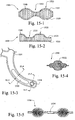
Figs. 15-1 to 15-5 show headgear including portions having variable thicknesses according to examples of the disclosed technology; -
Fig. 16 is a front view of a mask which may or may not include a vent component according to an example of the disclosed technology; -
Fig. 17 is a cross-sectional view along the line 17-17 ofFig. 16 ; -
Fig. 18 is a cross-sectional view of a headgear piece having thinned regions according to an example of the disclosed technology; -
Fig. 19 is a cross-sectional view of a headgear piece having more dense and less dense regions according to an example of the disclosed technology; -
Fig. 20 is a cross-sectional view along the line 20-20 ofFig. 5-1 ; -
Fig. 21 is a cross-sectional view along the line 21-21 ofFig. 6 ; -
Fig. 22-1 is a schematic representation of a double knit headgear or mask component according to an example of the disclosed technology; -
Figs. 22-2A and 22-2B illustrate an interlock knit headgear or mask component according to an example of the disclosed technology; -
Fig. 23 is a front view of headgear and a mask in position on a patient's head according to an example of the disclosed technology; -
Fig. 24 is a side view of the headgear and mask ofFig. 23 ; -
Fig. 25-1 is a side view of headgear including a rigidizer in position on a patient's head according to an example of the disclosed technology; -
Fig. 25-2 is an enlarged view of the headgear ofFig. 25-1 ; -
Fig. 26 illustrates a process of forming a rigidizer in headgear according to an example of the disclosed technology; -
Fig. 27 illustrates a process of forming a curved rigidizer in headgear according to an example of the disclosed technology; -
Fig. 28 shows 3D printed links used to form headgear according to an example of the disclosed technology; -
Fig. 29 shows a 3D printed headgear piece including a rigidizer according to an example of the disclosed technology; and -
Fig. 30 shows 3D printed headgear straps and clips according to an example of the disclosed technology. - The following description is provided in relation to several examples which may share common characteristics and features. It is to be understood that one or more features of any one example may be combinable with one or more features of the other examples. In addition, any single feature or combination of features in any of the examples may constitute an additional example or examples.
- In this specification, the word "comprising" is to be understood in its "open" sense, that is, in the sense of "including", and thus not limited to its "closed" sense, that is the sense of "consisting only of'. A corresponding meaning is to be attributed to the corresponding words "comprise", "comprised" and "comprises" where they appear.
- The figures illustrate headgear according to examples of the disclosed technology. In the illustrated examples, headgear are adapted to be removably attached to a patient interface to hold and maintain the patient interface in a desired position on a patient's face. While headgear may be illustrated as being used with a particular type of patient interface (e.g., mask), it should be appreciated that each headgear may be adapted for use with other suitable patient interfaces. That is, the patient interfaces are merely exemplary, and each headgear embodiment may be adapted for use with any suitable patient interface, e.g., full-face mask, nasal mask, mouth mask, nozzles or puffs, nasal prongs, etc, with any suitable configuration, e.g., with or without forehead support.
- Also, it should be appreciated that the headgear may be used with a new patient interface or the headgear may be retrofit to an existing patient interface.
- An example of a
headgear 200 manufactured according to an example of the disclosed technology is shown inFig. 2 . The headgear includes a rear portion for example a "crown" or "halo" 210 and a plurality ofstraps 220 attached to the rear portion. Therear portion 210 is adapted to accommodate the patient's occiput and thestraps 220 are configured to connect to upper and lower headgear attachment points (e.g. clips), as one skilled in the art will understand. It is noted that theheadgear 200 is merely an example and that other headgear configurations may be made in accordance with the disclosed technology. - The
headgear 200 is manufactured to shape (e.g., formed in one piece to shape otherwise known as "fully-fashioning" without the need to cut away any substantial amounts of material) thereby producing little or no waste material. Alternatively, the headgear may be divided into segments that are each manufactured to shape separately (e.g., by knitting) and then attached to one another.Fig. 2 demonstrates a single, unitary seamless structure having at least two regions (e.g. therear portion 210 and straps 220), wherein the at least two regions extend from a junction (the junction being the connection between thestraps 220 and the rear portion 210), where the straps extend at a different angular orientation to the rear portion. The rear portion and straps are formed in a continuous process (i.e. the material that makes up the component and the shape of the component are formed in a single step) - this is different to a process where a sheet of material is made and then cut to shape (this would not be considered a single step).Fig. 2 also shows that thestraps 220 branch out or extend at a different angle or direction to therear portion 210, without requiring seams or additional formation steps. - In
Fig. 3 , therear portion 210 and thestraps 220 are formed separately and subsequently connected. One skilled in the art will understand that any portions of theheadgear 200 can be formed separately and then later connected. In the example ofFig. 3 , thestraps 220 are stitched to therear portion 210; however other suitable methods such as knitting, sewing, crocheting, heat bonding with adhesive tape, gluing, welding (e.g., ultrasonic welding), etc. may be used. - A knitted component such as headgear is defined as being formed of "unitary knit construction" when constructed as a one-piece knit element that is substantially free of additional stitching or bonding processes.
- As shown in
Fig. 4-1 , thestraps 220 may be formed (e.g., by warp knitting) as a continuous piece that is subsequently cut as this procedure may further increase manufacturing efficiency. - Knitting various headgear sections in a continuous manner may be advantageous as there are no or very few additional manufacturing steps that would be required to sew, fuse, adhere or otherwise attach adjoining sections. As a result, the manufacturing process may have reduced steps, the amount of material waste is reduced, there would be virtually no seams in the headgear between the adjoining sections, and the headgear made of a fabric without distinctive joins or seams may be more comfortable for patients.
- A number of techniques can be used in accordance with the present technology to manufacture headgear to shape with little or no waste material. Preferably, the technique may produce a headgear that is a single, unitary, seamless structure. Techniques that may produce a single unitary seamless structure include mechanical manipulation of yarn including interlooping (such as knitting), interweaving and/or intertwining (including braiding, knotting and crocheting). An alternative technique of 3D printing may also create a headgear having a unitary, seamless structure.
- A manufacturing technique in accordance with the disclosed technology preferably has one or more of the following features:
- 1) produces little or no waste;
- 2) produces headgear that is comfortable for the patient;
- 3) produces headgear that is conformable;
- 4) produces headgear that is breathable;
- 5) produces headgear that may minimizes facial marking; and/or
- 6) produced headgear that is lightweight.
- . In accordance with an example of the disclosed technology, headgear may be formed by interlooping such as knitting (e.g., threading yarn or thread to form a knitted fabric). The headgear may be formed by flat knitting or circular knitting, however other forms of knitting may also be possible. Flat knitting and circular knitting may be preferable as they are able to create a headgear with a unitary, seamless structure. Flat or circular knitting machines may be utilized to create a weft knit or a warp knit. A variety of knitting processes including circular knitting and warp- or weft- flat knitting, may be utilized to manufacture the headgear component or components. Flat knitting may have some advantages, including but not limited to (1) the ability to locate floating yarns within, for example, a headgear strap, in order to provide extra cushioning or bulk, and/or (2) the ability to include extra loops of yarns on either the upper or lower surface of the headgear strap, thus creating the effect of a soft terry cloth material, for example, or creating an unbroken loop fabric for engagement with a hook tape fastener, and/or (3) the ability to knit a 3D dimensional spacer fabric construction adjacent to double-faced knit construction within a single unified headgear construction.
- Preferably, the headgear is formed primarily from multiple yarns that are mechanically manipulated through an interlooping process to produce a single unitary structure having various sections with different physical properties.
-
Fig. 7 illustrates the wale of aweft knit fabric 70, or the direction that the loops of one thread join to a loop of another thread. Thecourse 80, or the direction of the loops from a single thread is shown inFig. 8 .Figs. 9-1A and 9-1B illustrate a basic closedloop warp knit 90.Fig. 9-2 illustrates an example of a warp knit tricot jersey fabric structure in which a yarn is knitted in a vertical direction in a zig-zag manner, capturing other warp yarns, with the wale running somewhat parallel to the course. - Referring to
Figs. 9-1A, 9-1B, 9-2 and 10 , awarp knit 90, 90-1 comprises the wales and courses running parallel to one another, while in aweft knit 100 the wales run perpendicular to the course. The headgear and masks of the disclosed technology may be formed by either warp knit or weft knit. A warp knit, for example tricot, raschel or locknit, is typically more resistant to runs, easy to machine, and may utilize multiple yarns (allowing for the use of multiple colors or yarn types). A weft knit can be formed with a single yarn; however, use of multiple yarns is also possible. The headgear of the disclosed technology may be constructed of a warp knit or a weft knit. - Knitted fabrics may have different stretchability characteristics compared to woven fabrics. Knitted fabrics are typically more flexible than woven fabrics, which may only stretch in one direction (depending on the yarn they are made from), and therefore may provide a more comfortable fit for the patient. Knitted textiles may be constructed in such a way that the fabric has a two-way stretch - i.e. a first yarn oriented in a first direction has a lower flexibility than a yarn oriented in a second direction. This arrangement may be desirable along the straps of the headgear such that the straps can stretch along their length but not across their width, or vice versa. Alternatively, the knitted textile may have a four-way stretch i.e. yarn in a first direction and a second direction and both are flexible such that application to a strap would allow stretch in both lengthwise and crosswise directions.
- The example of
Fig. 12 shows astrap 1200 having a grain orcourse 1250, and illustrates how the direction of the grain or course affects stretch. The knitted fabric will tend to stretch more readily in the direction of the course. Therefore, headgear may be designed to stretch in certain directions and be more resistant to stretch in other directions. For example, thestrap 1200 will tend to stretch in its width direction A (from the patient's face to the back of the head) and may have limited stretch along the length of the strap. This configuration may increase stability of the headgear in the lengthwise direction while increasing fit range. Thestrap 1200 may be configured to stretch in certain directions and be resistant to stretch in other directions in order to better enable thestrap 1200 to hold a mask assembly on a patient's face in a manner that enhances the seal with the patient's face. - Referring to
Figs. 5-1 and 5-2 , amask 510 is held in position on a patient's face byheadgear 520. Themask 510 includes anelbow coupling portion 512 adapted to connect to an elbow (not shown) for supplying pressurized air to the mask. Lower mask clips 514 are adapted to connect to theheadgear 520. - The
headgear 520 includes upper headgear straps 530 and lower headgear straps 540 configured for connection to themask 510. An attachment member 544 (e.g., a lower headgear clip) may have connecting portions 544(1) (.e.g., holes) for receiving the strap material (e.g., thread or yarn). For example, yarn comprising the lower headgear strap may be looped through the holes 544(1) during fabrication of the strap to integrate theclip 544 and thestrap 540. - In an alternative example shown in
Fig. 6 , amask 610 andheadgear 630 are integrally formed as one piece. Themask 610 is knit to include open areas which function as vent holes 612. Anelbow coupling portion 614 includes holes 614(1) for receiving the yarn or thread thereby integrating themask 610 andelbow coupling portion 614. The mask may be made air tight by laminating or other suitable methods. - The
headgear 630 includes crown straps 632, 634,top strap 640, and lower headgear straps 650. The knit may be pulled tight or formed loosely to adjust the fit and enhance comfort in certain areas. For example, the illustrated crown straps 632, 634 have a looser knit which enhances breathability in the area near the top of the patient's head. In contrast, the lower headgear straps 650 have a tight knit which creates a more rigid strap for stabilizing the mask. Thetop strap 640 includes a thinnedregion 642 designed to avoid obstruction of the patient's vision. - Referring to
Figs. 11 and 11A , aknitted strap 1100 includes atop portion 1102, arear portion 1104, and alower portion 1106. Thelower portion 1106 may bifurcate or branch out at a junction to form thetop portion 1102 and therear portion 1104. The angular orientation of thetop portion 1102 may be different compared to the rear portion 1104e.g. thetop portion 1102 may extend at about 30-110 degrees, or about 90 degrees or perpendicular to therear portion 1104. The direction of the knit, or the grain orcourse 1150 of the knit, may be altered to adjust the shape or stretch of the fabric in certain areas. For example, the grain orcourse 1150 may be configured to curve the strap at a cheek region to avoid obstructing the patient's eyes. Further, as shown inFig. 11A , the grain orcourse 1150 may curve, as shown by the arrows B, to a split thereby forming thetop portion 1102 and the rear portion 1101. Such configurations of thetop portion 1102 and the rear portion 1101 may stabilize the straps in position on the patient's head and thus better enable thestrap 1100 to hold a mask assembly on a patient's face in a manner that enhances the seal with the patient's face. - The
strap 1100 may support a patient interface 1130 (e.g., a nasal mask) on the patient's face. Aconnector 1120 may be used to attach thestrap 1100 to thepatient interface 1130, and asupply tube 1140 may deliver breathable gas to the patient's airways via the patient interface. In the illustrated example, thepatient interface 1130 is positioned under the patient's nose and seals against the external surfaces of the patient's nose. - The headgear of the disclosed technology may further comprise a pocket, tunnel, layers and/or ribs. Such structures may be formed in one piece by circular or flat knitting. The pockets or tunnels may be reinforced with materials having a higher stiffness or rigidity than the knitted textile, thereby rigidizing the headgear. Rigidizing the headgear may better stabilize the mask in position on the user's face. Materials used for rigidizing the headgear may include plastics such as nylon, polypropylene, polycarbonate, or higher stiffness textiles such as braided ropes. Preferably, the rigidizing of the headgear may be positioned at boney regions of the patient's head, for example the cheeks, occiput or crown. The reinforcing structure may be inserted during the knitting process, for example, a stiffer or flatter yarn or a rigid polymer element may be inserted into the knit construction, during or after the knitting process. The strands or rigid components would function to withstand tension and bear the stresses e.g., due to tightening of the headgear straps for therapy, or to stabilise the mask better, or would assist to act as coupling or fastening agents to attach the headgear piece(s) to the mask interface.
- Alternatively, the pockets or tunnels may be cushioned to add comfort. For example, pockets or tunnels may be filled with foam, gel, floating yarn, looped yarn or other cushioning material.
- Preferably, the headgear is formed by flat knitting or circular knitting, wherein the headgear has selvedges. That is, the headgear may be formed to have a finished configuration such that the ends of the yarns used to construct the headgear are substantially absent from the edges of the headgear components. An advantage of fashioning the headgear components to the finished shape is that the yarns are not being cut, and are thus less likely to unravel and may require fewer finishing steps. By forming finished edges, the integrity of the headgear is maintained or even strengthened and fewer or no post-processing steps are required to either (1) prevent unravelling of the headgear component and/or (2) create an edge that is distinct yet soft (such as in ultrasonically cutting and sealing a 'soft edge' on a fabric-foam-fabric laminate material) and/or (3) enhance the aesthetic and durability characteristics of the headgear.
- The headgear of the disclosed technology may be formed by a regular or irregular pique knit. A pique knit will orient a first yarn on the right side (non-patient contacting side that is visible once headgear is donned) and a second yarn on the wrong side (the patient contacting side that is not visible once the headgear is donned). That is, the yarn exposed on the right side may be different to the yarn exposed on the wrong side. For example, the yarn on the right side may have a pleasant visual appearance and the yarn on the wrong side may have a nice hand feel for contacting the patient's skin. Alternatively, or in addition, the yarn on the right side may have a first moisture wicking property and the wrong side may have a second moisture wicking property. For example, the yarn on the right side may have a high percentage of microfiber having a first moisture wicking property and the wrong side may have a high percentage of non-microfiber having a second moisture wicking property.
- The headgear may be preferably formed as a unitary knit structure which may also be uniform in material and properties, for simplicity, but preferably it will be formed as a unitary structure including various sections that have different physical properties, joined in a seamless manner. The various sections may exhibit, for example but not limited to, different degrees of strength, abrasion resistance, wear resistance, flexibility, enhanced durability, higher or lower moisture absorption (moisture absorbability), moisture-wicking ability, water affinity, breathability or air-permeability, liquid permeability, stretch or stretch-resistance, compressibility, cushioning ability, support, stiffness, recovery, fit, and form. The various sections may be constructed to exhibit variations in directional stretch, such as four-way stretch, or bi-directional stretch, a tailored level of stretch resistance, or no stretch. This may be achieved by, for example but not limited to, selecting a particular yarn or knit construction type.
- The headgear as a unified seamless structure may be formed in one piece with uniform characteristics, or from two or more sections with varying characteristics. The two or more headgear sections may differ by way of using two or more different yarns of different twist, denier, fibre composition, etc., thus imparting different physical properties to the headgear structure. The two or more headgear sections may differ by way of using two or more various knit stitch types, thus imparting unique physical properties to the two sections.
- Whereas one region may incorporate, for example, elastane or PBT (Polybutylene terephthalate polyester) to enhance stretch, the other region may incorporate, for example, nylon or polyester to enhance durability. Similarly, while one region of the headgear may incorporate yarn with one denier, the other region may include a yarn with a greater or reduced denier, crimp or texture, in order to customize the cushioning, thickness or bulk.
- The two or more sections within a headgear construction may be connected by using tuck stitches or other knit stitches that, for example, join a first section to a second section in a seamless manner. This would be achieved by knitting the first section, then knitting the tuck stitches between the first knitted section and a second knitted section, then knitting the second section. The tuck stitches are utilized to seamlessly connect sections between wales, especially when using a narrow-tube circular knitting machine.
- The headgear piece may be finished without a seam. If it is made with an undyed yarn, this may be achieved by finishing the knitting process with a yarn that contains water-soluble fibres. The water-soluble fibers permit the fabric to shrink in the dyeing process and provides a neatly-finished edge, eliminating the need to create an additional seam on the edge.
- In order to enhance manufacturing efficiency, knitting machines may also be utilized to form a series of joined headgear components, such as straps or crown components. That is, the knitting machines may form a single component that includes a plurality of headgear pieces. Each of the headgear segments may have substantially identical shapes and sizes. Alternatively, each of the headgear pieces may even have different shapes and sizes, which may be programmed in sequence. Moreover, a knit release area (which may consist of, for example but not limited to, dissolvable yarns; loosely knitted yarns, finer denier yarns or easy-to-tear placeholder yarns) may be knitted into the series of headgear components in order to allow the various headgear parts, for example, straps, to be separated without the need for cutting operations.
- In an example of the disclosed technology, headgear may be formed using spacer fabric material. A spacer fabric can be defined as a textile having an upper ground structure or layer, a lower ground structure or layer, and a floating or traversing yarn woven between the upper ground structure and lower ground structure to form a matrix like textile. The upper ground structure and lower ground structure may be formed from a fabric. The upper ground structure may have different properties to the lower ground structure, for example they may have different stretch, stiffness, flexibility, hand feel, or other characteristics. The upper and lower ground structures may be substantially parallel to one another. Spacer fabrics may be formed by flat knitting. At least one side (i.e. upper or lower ground structure) may be formed from a fabric having yarn of, for example, about 30-100 denier, 20-300 denier, or 50-200 denier for a pleasant hand feel.
- In the example of
Figs. 13 and 13a , arear portion 1310 includes aninner fabric 1320 for interfacing with a patient, anouter fabric 1330, andspacer threads 1340 joining the inner and outer fabrics. Theinner fabric 1320 may be configured to be soft and capable of wicking moisture in order to enhance comfort. The outer fabric may be designed to have a low friction surface so as to enable movement while sleeping without disrupting the position of the mask. The outer fabric may also have an anti-soil surface and may further include unbroken loop to facilitate attachment of straps. - In another example, headgear may be formed as a knitted tube having an
inner space 1405, as shown inFigs. 14-1 to 14-4 . Atubular headgear piece 1400 includes an outer fiber/interfacing fabric 1430, an inner spacer fiber or pile (connecting layer) 1440, and an inner fiber/fabric 1450. Thetubular piece 1400 is constructed by a device having inner andouter needles interfacing fabric 1430, the inner spacer fiber, and the inner fiber/fabric 1450. - The
tubular piece 1400 may flatten out in use, when under tension, to form a low profle headgear piece (e.g., a strap), as shown inFig.14-3 . Further, referring toFig. 14-4 , atubular strap 1460 may have a varying diameter such that a portion connecting to therear portion 1310 is wider than the ends adapted to connect to the mask. This configuration may reduce the visual obtrusiveness of theheadgear strap 1460. - In another example, the
inner space 1405 may be configured to transit air, thus forming an air delivery conduit. PCT ApplicationPCT/AU2012/000667, filed June 8, 2012 PCT/AU2012/000667 - Turning to
Figs. 15-1 and 15-2 , the depth or thickness of the headgear may be varied by altering the length of the spacer yarns (spacer threads). Aheadgear piece 1500 includes aninner fabric 1520, anouter fabric 1525, andspacer threads 1540. Theheadgear piece 1500 may includethinner regions 1510 andthicker regions 1520. In the example ofFig. 15-1 , a gradual transition between thethinner regions 1510 and thethicker regions 1520 is formed. In contrast, a steeper transition can be seen in the example ofFig. 15-2 . One benefit of a tailored cushion with differing thicknesses might be cushioning which changes in thickness to correspond to certain facial bone/muscle structure creating contour, comfort and padding, or thinner zones for breathability and temperature management. - Referring to
Figs. 15-3 to 15-5 , the thickness of astrap 1530 can also be varied to createrigid portions 1532 and connectingportions 1534. Therigid portions 1532 may function as rigidizers or stabilizers and provide form in certain areas of the headgear. The connectingportions 1534 may include a hole or other structure utilized to connect thestrap 1530 to a mask. - In addition to varying the depth or thickness of the headgear, gaps may be formed in the spacer threads. These gaps may be utilized to form vent holes in a mask or create flexible areas of the headgear, for example. In
Figs. 16 and 17 , amask 1610 includes aninner fabric 1620, anouter fabric 1630, andspacer threads 1640.Voids 1660 in the spacer thread may be used to createvent holes 1650 in the mask. To facilitate this feature, the inner 1620 and outer 1630 fabrics are thinned in the areas of thevoids 1660. Ends of the mask may be welded, knit, or joined in any other suitable manner. - Alternatively, the
voids 1660 may be thermoformed or otherwise compressed to form thinnedregions 1810, as shown inFig. 18 . The thinnedregions 1810 may form hinges or areas adapted to bend the headgear around a curve (e.g., around the patient's occiput). - In a further example, the
spacer threads 1640 may be unevenly spaced to create lessdense areas 1910 and moredense areas 1920. These areas may permit flexibility of the headgear to be adjusted as desired. For example, the headgear may be stiffer (dense area 1920) at the cheek bone region and flexible (less dense 1910) at the cheek muscle region. - In alternative examples, the
headgear 520 and theheadgear 630 ofFigs. 5-1 and6 may include spacer material, as shown in the cross-sectional views ofFigs. 20 and21 . The spacer fabric construction may provide more cushioning, breathability, moisture management (e.g. moisture absorbability or wicking), and/or desirability (e.g., comfort and/or aesthetic appeal). - Referring to
Fig. 20 , theupper headgear strap 530 may include an inner fabric 530(1), an outer fabric 530(2), and spacer yarns. 530(3). Further, the edge of thestrap 530 may be knitted to draw the outer fabric 530(2) into engagement with the inner fabric 530(1) to create an integrated seamless edge 530(4). Alternatively, the inner and outer fabrics may be welded (e.g., ultrasonic welded) at the edge of thestrap 530. - Referring now to
Fig. 21 , thecrown strap 634 may include an inner fabric 634(1), an outer fabric 634(2), and spacer yarns 634(3). Additionally, the outer fabric 634(2) may be brushed or otherwise treated to form unbroken loop material for receiving hook material. - Alternatively, the headgear may be constructed by braiding, crocheting, a net construction or raschel pattern, a single layer knit or a double layer knit such as an interlock or jersey, or even via additive manufacture (3D printing). In the case of a basic single face fabric or double face knit, it may be preferable to use a textured yarn which may provide appropriate cushioning and bulk, to enhance comfort to the patient.
- Referring to
Figs. 4-2 to 4-4 , a warp knittedstrap 420 formed of spacer fabric is shown. Thestrap 420 includes aninner fabric 431, anouter fabric 433, andspacer yarns 435. The strap may be formed of nylon and/or polyester, or any other suitable materials. Theinner fabric 431 and theouter fabric 433 may have a soft surface having a high density. The strap may have awider portion 422 adapted to connect to another headgear member (e-.g-., a rear portion) and athinner portion 424 adapted to connect to a mask. The spacer yarns or pile may be formed to be shear resistant. The inner and outer fabrics are knitted together at theselvedges 437 to enclose the spacer pile. In another example, as shown inFig. 4-4 , theouter fabric 433 includesunbroken loop material 440 for receiving hook material. - In an example, as shown in
Fig. 4-2 , d1 may be about 22.5-42.5 mm, e.g., 32.5 mm, d2 may be about 30-50 mm, e.g., 40 mm, d3 may be about 152-292 mm, e.g., 222 mm, d4 may be about 11-17 mm, e.g., 14 mm, and d5 may be 14-22 mm, e.g., 18 mm. Further, as shown inFig. 4-3 , d1 may be about 1.75-3.25 mm, e.g., 2.5 mm and d2 may be about 2.25-3.75 mm, e.g., 3 mm. - In
Figs. 4-5 to 4-9 , a warp knittedstrap 450 includes aninner fabric 461, anouter fabric 463, andspacer yarns 465. In contrast to thestrap 420 above, thestrap 450 has a constant width. The spacer yarns or pile may be formed to be shear resistant. The inner and outer fabrics are knitted together at theselvedges 467 to enclose the spacer pile. In another example, as shown inFig. 4-7 , theouter fabric 463 includesunbroken loop material 470 for receiving hook material. In a further example theouter fabric 463 may be elasticated to form a high-tension outer fabric 463-1, as shown inFig. 4-8 . The elasticated outer fabric 463-1 pulls theselvedges 467 to the outer surface of the strap, and may function to cause the headgear strap to curl upwards and inwards towards the outer fabric layer of the strap. In cross section, as shown inFig 4-8 , the strap may have the appearance of the letter C. This arrangement may be advantageous in reducing facial marking as the strap does not have a distinct edge when pressed against the patient's skin, since the edge curls up away from the skin. - In an example, as shown in
Figs. 4-5 and 4-6 , d1 may be about 1.75-3.25 mm, e.g., 2.5 mm, d2 may be about 2.25-3.75 mm, e.g., 3 mm, and d3 may be about 11-17 mm, e.g., 14 mm. - Alternatively, in accordance with another example, headgear may be formed to shape having an inner and outer face with no space in between these faces.
Fig. 22-1 is a schematic representation of a double knit andFigs. 22-2A and 22-2B illustrate an interlock knit. InFigs. 22-1, 22-2A and 22-2B , aninner fabric 2210 and anouter fabric 2220 are knitted in such close proximity that they form a double faced fabric such as interlock, double knit or double jersey. As shown inFig. 22-1 , the inner 2210 and outer 2220 fabrics are knitted at the same time with aspacer yarn 2230 that pulls the inner 2210 and outer 2220 fabric layers together. However, in the example ofFigs. 22-2A and 22-2B , the inner 2210 and outer 2220 fabrics are knitted concurrently (at the same time) without the need for an additional spacer yarn in a manner commonly known as interlock, whereby there are two sets of yarns which form the inner and outer fabric respectively. - Double faced or knit fabrics may be beneficial for use in headgear as the fabric may be flatter (i.e. thinner in fabric thickness, not thinner in strap width) than most conventional headgear materials (e.g. foam laminate) so as to be as unobtrusive as possible for the patient, but more substantial, dense, durable, robust or stiff than a single-knit. A double knit fabric may also permit a first characteristic or pattern/structure on one side of the fabric with a second characteristic or pattern/structure on the opposite side of the fabric. For example, a soft yarn may be provided on the patient contacting side, and a more durable yarn or construction on the non-patient contacting side. In a further example, a wicking microfiber may be provided on the patient contacting side and a hydrophilic material may be provided on the non-patient contacting side. In a further example a cotton yarn may be provided on the patient contacting side and a polyester outer may be provided on the non-patient contacting side. A double knit fabric may be preferable to a spacer fabric as the double knit may be less expensive and less complex due to the smaller number of layers.
- The number of stitches can be adjusted to enhance comfort, fit and/or performance. For instance, the number of stitches may be varied to create ruffles which may function to reduce facial marking. In the example of
Fig. 23 , amask 2305 is supported byheadgear 2310. The mask includes aseal portion 2307 which seals against the patient's face. Theheadgear 2310 includesstraps 2312 and may also include anupper strap 2314 to assist in stabilizing the mask. The number of stitches through amiddle portion 2320 of thestraps 2312 is less than the number of stitches near the outer edge of the straps. The increased number of stitches at the edge portion causes the strap to form ruffles 2330. It will be understood that the number of stitches may be adjusted in any portion of the headgear to achieve a desired fit. - Referring back to
Figs. 13 and 13a , the number of stitches in therear portion 1310 may be adjusted to cause the rear portion to form a shape configured to conform to a patient's head. The truncated cone shape inFig. 13 is shown to illustrate an example of adjusting the number of stitches to change the shape. For example, adistal portion 1312 of therear portion 1310 may have fewer stitches than aproximal portion 1314. In an example, the distal portion may be comprised of 100 stitches and the proximal portion may be comprised of 200 stitches. This arrangement may cause the proximal portion to have an increased diameter thereby flaring outwardly into a truncated cone shape. - In another example, the thread count may vary across the fabric to enhance comfort, fit and/or performance. For example, the thread count may be higher in regions requiring greater stiffness (e.g., cheek region, occiput). In regions (e.g., along the straps) where a lower stiffness is desired, however, the thread count may be lower thereby permitting the material to flex more easily.
- The thread count, and therefore the stiffness, may be determined by the type of yarn, the type of stitch (e.g., a criss-cross stitch may be stiff), and the distance between stitches.
- The headgear may include one or more rigidizers that are structured to add rigidity, stiffness and/or stability to the headgear and anchor the headgear in position in use. In an example, a rigidizer is formed integrally with a strap. For instance, in
Figs. 25-1 and 25-2, yarn having a higher stiffness than the surrounding yarn of theheadgear 2500 may be knitted in specific regions (e.g., cheek region or crown region) to form arigidizer 2510. Therigidizer 2510 may stiffen the headgear to provide stability for the mask. In addition, therigidizer 2510 may be shaped to form aheadgear clip 2520 for attachment to a patient interface 2530 (e.g., nasal mask). - In another example, the yarn forming the
rigidizer 2510 may be melted or fused to further stiffen the yarn into a welded rigidizer 2610, as shown inFig. 26 . Preferably, the rigidizer yarn has a lower melt temperature than the surrounding yarn such that the welded rigidizer 2610 can be formed without deforming the surrounding yarn. In an example, the rigidizer yarn includes polypropylene and the surrounding yarn includes nylon or other non-piastic material such as cotton or wool. - The knitted headgear component may incorporate a thermoplastic yarn that is fused in different regions of the knitted component to impart different properties. By heating the thermoplastic polymer materials, adjacent yarns, filaments, or fibers may fuse to each other in those areas to lock the knit loops together, thereby increasing stiffness or wear-resistance or stability of the mask on the patient's face. As an alternative, the entirety of the knitted headgear component may be formed from yarns that incorporate thermoplastic polymer materials, and only specific portions corresponding with fused areas may be heated to modify the properties.
- The rigidizer may be formed by a
flat tool 2650, as shown inFig. 26 , or acurved tool 2750, as shown inFig. 27 . InFig. 27 , acurved headgear 2700 having acurved rigidizer 2710 is formed. - The inner or outer layer of headgear fabric may be formed to include a slit (or gap). A rigid or semi-rigid element may be inserted through the slit to form a support positioned between the inner layer and the outer layer of the headgear. In an example shown in
Fig. 14-5 , a similar hollow structure (toFig. 14-1 to 14-4 ) could also be knitted in a flattened-out manner, for instance on a warp knitting machine, by concurrently knitting an outer fabric 461-2, that interfaces with the patient, to a layer of spacer yarns 465-2, which at the same time is knitted to an inner fabric 463-2 that encases the spacer yarns, which is covered in turn by knitting a pocket layer 469-2 that forms a gap 470-2 (or pocket). The pocket layer 469-2 is connected to the outer fabric 461-2, the spacer yarns 465-2 and/or the inner fabric 463-2 only near the selvedge 467-2 of the knitted structure. - As shown in
Figs. 14-6 and 14-6A , the gap 470-2 could form a hollow pocket in a strap 450-1, for example, which may be filled with a separate rigidizer 472-2, for example, or may be used to locate another related mask component or attachment mechanism. The spacer fabric provides a soft cushioning between a hard part (e.g., the rigidizer 472-2) and the patient's face, and the pocket functions to locate a hard plastic part or cushion attachment into the soft fabric headgear strap encasement, which may be fastened in place by, for example, friction, clips, adhesives, heat laminate or overstitching. - Yarn may be utilized to create the headgear of the disclosed technology.
- The yarn may be synthetic, and may be twisted or textured, and could be made from, but not limited to nylon, polyester, acrylic, rayon, or polypropylene. The yarn could be a conventional staple yarn, a microfiber yarn, or combination of both.
- The yarn may incorporate an elastane fiber or filament to provide stretch and recovery properties, such as fibers bearing the LYCRA trademark from the DuPont company.
- The yarn may be made of synthetic materials, or natural fibres such as cotton, wool or bamboo, or natural filament such as silk.
- The yarns used to construct any component of the headgear may be formed of a monofilament or a plurality of single filaments, that is, a multifilament yarn.
- The yarn may include separate filaments that are each formed of different materials. The yarn may also include filaments that are each formed of two or more different materials, such as bicomponent yarn with filaments having a sheath-core configuration or two halves formed of different materials. Different degrees of twist or crimping, as well as different deniers, may affect the properties of the headgear.
- The materials utilized to construct the headgear components may be made recyclable or biodegradable, for example, the yarns may include recyclable or biodegradable fibers or filaments.
- Areas of the headgear subject to greater wear (for example but not limited to areas or regions coming into contact with a patient's pillow), such as an area of headgear located at the back of the head or nape of the neck, may possibly be more densely fabricated and may thus be a heavier weight and less extensible. Conversely, this area may be subject to the greatest amount of moisture accumulation through sweat, and therefore may need to be made of a thin, yet strong, net-like construction with a custom aperture pattern. In this case, the abrasion-resistance may need to be inherent in the yarn properties only.
- In another example, headgear may be manufactured to shape using a 3D printer. As shown in
Fig. 28 , a 3D printer may be used to print a plurality ofconnected links 2802 thereby forming a flexible 3D printedtextile 2804. Referring toFig. 29 , aheadgear piece 2900 may be formed to include arigidizer 2920. The rigidizer includesholes 2922 throughwhich the links of thetextile 2904 may pass as the textil is printed to integrate the textile and the rigidizer. The rigidizer could be made from any suitable material (e.g., a polymer such as Nylon 12 or a sintered solid from a metal powder, or any other material able to used for an additive manufacture process). As the additive manufacture ("3D Printing" process technologies improve, it is envisioned that the material selection will become broader for the purposes of 3D printing textiles, with the optional inclusion of a rigid component. Structure could be inherent in material or by virtue of structure. - Further, as shown in
Fig. 30 , a 3D printedstrap 3004 may be integrated into holes 3012(1), 3014(1) of male andfemale clips - Custom headgear may be manufactured for an individual patient in accordance with an example of the disclosed technology. Data regarding the shape and size of the patient's head is acquired (e.g., via photo, 3D scan). Measurements that may be used to manufacture a custom headgear may include the circumference of the patient's crown, length from the occiput to the crown, and the position of the patient's ears, eyes and nose. Visual modeling software (e.g., CADCAM) operating on a computer may create a custom headgear model according to the patient's measurements and needs. This model may then be sent to a machine (e.g, a knitting machine or 3D printer) for creation of the headgear.
- It is noted that features of the disclosed technology have been particularly described with reference to headgear. However, all of the features described in relation to headgear may also be usable in any mask constructed in accordance with the disclosed technology.
- While the technology has been described in connection with several examples, it is to be understood that the technology is not to be limited to the disclosed examples, but on the contrary, is intended to cover various modifications and equivalent arrangements included within the spirit and scope of the technology. Also, the various examples described above may be implemented in conjunction with other examples, e.g., one or more aspects of one example may be combined with one or more aspects of another example to realize yet other examples. Further, each independent feature or component of any given assembly may constitute an additional example. In addition, while the technology has particular application to patients who suffer from OSA, it is to be appreciated that patients who suffer from other illnesses (e.g., congestive heart failure, diabetes, morbid obesity, stroke, bariatric surgery, etc.) can derive benefit from the above teachings. Moreover, the above teachings have applicability with patients and non-patients alike in non-medical applications.
- Further preferrred embodiments are described by the following items:
- 1. A headgear assembly for use in supporting a respiratory mask in position on a patient's face for positive pressure treatment of the patient, the headgear comprising:
at least one headgear component formed of a unitary, substantially seamless structure, the at least one headgear component comprising a junction. - 2. The headgear of
item 1, wherein the at least one headgear component includes at least first and second headgear components having a substantially seamless connection to one another, the at least first and second headgear components meeting at the junction. - 3. The headgear of
item 2, further comprising stitches connecting the at least first and second headgear components to one another in a substantially seamless manner. - 4. The headgear of
item 3, wherein the stitches are tuck stitches. - 5. The headgear of any one of items 1-4, wherein the at least first and second headgear components have different properties.
- 6. The headgear of
item 5, wherein the first headgear component has a value associated with a property that is different from a value of the second headgear component associated with the property. - 7. The headgear of
item 6, wherein the property is at least one of strength, abrasion resistance, wear resistance, flexibility, durability, moisture absorbability, moisture-wicking ability, breathability, air-permeability, liquid-permeability, stretchability, compressibility, cushioning ability, stiffness, and recovery. - 8. The headgear of any one of items 2-7, wherein the at least first and second headgear components comprise different materials.
- 9. The headgear of
item 8, wherein a material of the first headgear component has a different twist, crimp, texture, denier and/or fiber composition than a material of the second headgear component. - 10. The headgear of any one of items 2-9, wherein the first headgear component has a different stitch type than the second headgear component.
- 11. The headgear of any one of items 2-10, wherein at least one of the at least first and second headgear components includes spacer fabric having an inner layer, an outer layer and spacer threads joining the inner layer and the outer layer, the inner layer being knitted to the outer layer to form a substantially seamless edge.
- 12. The headgear of any one of items 2-11, wherein at least one of the at least first and second headgear components comprises a strap.
- 13. A headgear assembly for use in supporting a respiratory mask in position on a patient's face for positive pressure treatment of the patient, the headgear comprising:
- at least one headgear component having a substantially seamless structure, the headgear component including a patient contacting side and a non-patient contacting side,
- wherein the patient contacting side has a first characteristic associated with at least one property and the non-patient contacting side has a second characteristic associated with the at least one property, and the first characteristic is different from the second characteristic.
- 14. The headgear of item 13, wherein a first material is provided on the patient contacting side and a second material is provided on the non-patient contacting side.
- 15. The headgear of any one of items 13 and 14, wherein the at least one property is softness, durability, moisture-wicking ability, or water-affinity.
- 16. The headgear of any one of items 13-15, wherein the headgear component is knitted such that a first yarn is oriented on the patient contacting side and a second yarn is oriented on the non-patient contacting side.
- 17. The headgear of anyone of items 13-16, wherein the headgear component is double knit.
- 18. The headgear of any one of items 13-16, wherein the headgear component is pique knit.
- 19. The headgear of any one of items 13-18, wherein the headgear component comprises a strap.
- 20. A method of forming headgear for use in holding a respiratory mask in position on a patient's face, comprising:
- knitting at least one headgear component to have a substantially seamless structure, the headgear component including a patient contactine side and a non-patient contacting side;
- wherein the patient contacting side has a first characteristic associated with at least one property and the non-patient contacting side has a second characteristic associated with the at least one property, and the first characteristic is different from the second characteristic.
- 21. The method of
item 20, wherein a first material is provided on the patient contacting side and a second material is provided on the non-patient contacting side. - 22. The method of any one of
items - 23. The method of any one of items 20-22, wherein the headgear component is knitted such that a first yarn is oriented on the patient contacting side and a second yarn is oriented on the non-patient contacting side.
- 24. The method of any one of items 20-23, wherein the headgear component is double knit.
- 25. The method of any one of items 20-23, wherein the headgear component is pique knit.
- 26. The method of any one of items 20-25, wherein the headgear component comprises a strap.
- 27. A headgear assembly for use in supporting a respiratory mask in position on a patient's face for positive pressure treatment of the patient, the headgear comprising:
- at least one headgear component,
- wherein the headgear compon items nprises yarn, the headgear component has a first region having a first density of the yarn and a second region having a second density of the yarn.
- 28. The headgear of item 27, wherein the first region comprises a first yarn having a first denier, and the second region comprises a second yarn having a second denier.
- 29. The headgear of any one of items 27-28, wherein the first region has a greater density of yarn than the second region such that the first region is more stiff, less extensible, and/or less permeable than the second region.
- 30. A headgear assembly for use in supporting a respiratory mask in position on a patient's face for positive pressure treatment of the patient, the headgear comprising:
- a single unitary structure including at least two adjacent headgear regions,
- wherein a release area is provided between the at least two adjacent headgear regions adapted to separate the at least two adjacent headgear regions from one another without cutting.
- 31. The headgear of item 30, wherein the release area comprises dissolvable yarns, loosely knitted yarns, fine denier yarns and/or easy-to-tear placeholder yarns.
- 32. Headgear for use in supporting a respiratory mask in position on a patient's face for positive pressure treatment of the patient, the headgear comprising:
a strap at least partly constructed of spacer fabric. - 33. The headgear of item 32, wherein the spacer fabric has an inner layer formed of shear resistant pile.
- 34. A method of forming headgear for use in holding a respiratory mask in position on a patient's face, comprising:
- a) knitting a yarn or thread to form a strap adapted to at least partially support the mask, the strap being connected to an attachment member, the attachment member adapted to connect the strap to the mask; and
- in step a), looping the yarn or thread through a connecting portion formed in the attachment member to connect the strap to the attachment member.
- 35. A mask system for use in treating a patient for sleep disordered breathing, comprising:
- a mask assembly adapted to seal against the patient's face thereby forming a breathing cavity, the mask having one or more portions constructed of a first knitted fabric; and
- a headgear connected to the mask to at least partially support the mask on the patient's face, the headgear having one or more portions constructed of at least one of the first knitted fabric and a second knitted fabric.
- 36. The mask system of item 35, wherein the first knitted fabric and the second knitted fabric are made of the same material.
- 37. A method of forming headgear for use in holding a respiratory mask in position on a patient's face, comprising:
knitting a yarn or thread to form a headgear component adapted to at least partially support the mask, wherein a grain or course of the knit is altered to form a curved portion of the headgear component. - 38. The method of item 37, wherein the curved portion is adapted to enhance comfort to the patient and/or improve performance of the respiratory mask.
- 39. A method of forming headgear for use in holding a respiratory mask in position on a patient's face, comprising:
knitting a yarn or thread to form a headgear component adapted to at least partially support the mask, wherein a grain or course of the knit is arranged to allow or disallow stretch in at least one portion of the headgear component. - 40. The method of item 39, wherein the arrangement of the grain or course is adapted to enhance comfort to the patient and/or improve performance of the respiratory mask.
- 41. Headgear for use in supporting a respiratory mask in position on a patient's face for positive pressure treatment of the patient, the headgear comprising:
a first component at least partly constructed of spacer fabric, the spacer fabric including an inner fabric, an outer fabric and an inner spacer fiber interconnecting the outer fabric and the inner fabric, wherein the inner fabric delimits a hollow interior area. - 42. A method of forming headgear for use in holding a respiratory mask in position on a patient's face, comprising:
- knitting a yarn or thread to form a headgear component adapted to at least partially support the mask, the headgear component being at least partly constructed of spacer fabric and having an inner layer formed of spacer yarns; and
- altering a length or density of the spacer yarns in at least one portion of the headgear component to vary an attribute of the headgear component.
- 43. A mask assembly for use in treating a patient for sleep disordered breathing, comprising:
one or more portions constructed of spacer fabric, the spacer fabric having an inner layer formed of spacer yarns, the inner layer having at least one portion forming a vent hole, wherein the at least one portion is substantially void of spacer yarns. - 44. A method of forming headgear for use in holding a respiratory mask in position on a patient's face, comprising:
- knitting a yarn or thread to form a first knitted fabric;
- concurrently knitting a or thread to form a second knitted fabric; and
- at the same time knitting the first knitted fabric to the second knitted fabric such that one of the first knitted fabric and the second knitted fabric forms an inner fabric adapted to interface with the patient.
- 45. A method of forming headgear for use in holding a respiratory mask in position on a patient's face, comprising:
- knitting a yarn or thread to form a headgear component adapted to at least partially support the mask; and
- altering a number of stitches in at least one portion of the headgear component to vary an attribute of the headgear component.
- 46. A method of forming headgear for use in holding a respiratory mask in position on a patient's face, comprising:
- knitting a yarn or thread to form a headgear component adapted to at least partially support the mask; and
- altering a thread count or stitch style in at least one portion of the headgear component to vary an attribute of the headgear component.
- 47. A headgear assembly for use in supporting a respiratory mask in position on a patient's face for positive pressure treatment of the patient, the headgear comprising:
- a first headgear component constructed of a knitted fabric, the knitted fabric including a first or thread and a second or thread having a higher stiffness than the first or thread,
- wherein the second or thread is arranged to provide a rigidizing portion of the first headgear component.
- 48. A method of forming headgear for use in holding a respiratory mask in position on a patient's face, comprising:
- providing a base headgear material to form a headgear component adapted to at least partially support the mask; and
- knitting a yarn or thread into the base headgear material, the or thread having a higher stiffness than the base material;
- wherein the yarn or thread is arranged to provide a rigidizing portion of the headgear component.
- 49. The method of item 48, wherein the yarn or thread is melted to further stiffen the rigidizing portion, and the yarn or thread has a lower melt temperature than the base headgear material.
- 50. A method of forming headgear for use in holding a respiratory mask in position on a patient's face, comprising:
3D printing a textile to form at least a first headgear component adapted to at least partially support the mask. - 51. A method of manufacturing custom headgear for use in holding a respiratory mask in position on a patient's face, comprising:
- acquiring data related to the shape and size of the patient's head;
- creating an electronic headgear model with a computing device and computer aided design program in accordance with the acquired data; and
- forming at least a first headgear component corresponding at least in part to the electronic headgear model.
Claims (6)
- A mask system for treating a patient for sleep disordered breathing, comprising:a mask adapted to seal against a patient's face thereby forming a breathing cavity for positive pressure treatment; andheadgear to support the mask in position on the patient's face during treatment, the headgear comprising a knitted textile formed of a unitary structure that is fully-fashioned to shape in one unitary piece, without being cut from a sheet of material,wherein the knitted textile has an inner layer and an outer layer, andwherein the inner or outer layer is formed to include a slit or gap and a rigid or semi-rigid element is inserted through the slit or gap to provide rigidity to the headgear.
- The mask system of claim 1, the headgear further comprising a rear portion connected to the knitted textile.
- The mask system of claim 1, wherein the rigidizer is fastened in place by adhesive.
- The mask system of claim 1, wherein the rigidizer comprises plastic.
- The mask system of claim 1, wherein the rigidizer is shaped to form a headgear clip for attachment to the mask.
- The mask system of claim 1, wherein the mask is configured to, in use, be positioned under the patient's nose and seal against external surfaces of the patient's nose.
Applications Claiming Priority (4)
| Application Number | Priority Date | Filing Date | Title |
|---|---|---|---|
| US201161526057P | 2011-08-22 | 2011-08-22 | |
| US201261670495P | 2012-07-11 | 2012-07-11 | |
| PCT/AU2012/000979 WO2013026091A1 (en) | 2011-08-22 | 2012-08-21 | Manufactured to shape headgear and masks |
| EP12825595.7A EP2747826B1 (en) | 2011-08-22 | 2012-08-21 | Manufactured to shape headgear and masks |
Related Parent Applications (2)
| Application Number | Title | Priority Date | Filing Date |
|---|---|---|---|
| EP12825595.7A Division-Into EP2747826B1 (en) | 2011-08-22 | 2012-08-21 | Manufactured to shape headgear and masks |
| EP12825595.7A Division EP2747826B1 (en) | 2011-08-22 | 2012-08-21 | Manufactured to shape headgear and masks |
Publications (1)
| Publication Number | Publication Date |
|---|---|
| EP3848079A1 true EP3848079A1 (en) | 2021-07-14 |
Family
ID=47745766
Family Applications (3)
| Application Number | Title | Priority Date | Filing Date |
|---|---|---|---|
| EP12825595.7A Active EP2747826B1 (en) | 2011-08-22 | 2012-08-21 | Manufactured to shape headgear and masks |
| EP21156294.7A Pending EP3851146A1 (en) | 2011-08-22 | 2012-08-21 | Manufactured to shape headgear and masks |
| EP21156279.8A Pending EP3848079A1 (en) | 2011-08-22 | 2012-08-21 | Manufactured to shape headgear and masks |
Family Applications Before (2)
| Application Number | Title | Priority Date | Filing Date |
|---|---|---|---|
| EP12825595.7A Active EP2747826B1 (en) | 2011-08-22 | 2012-08-21 | Manufactured to shape headgear and masks |
| EP21156294.7A Pending EP3851146A1 (en) | 2011-08-22 | 2012-08-21 | Manufactured to shape headgear and masks |
Country Status (7)
| Country | Link |
|---|---|
| US (3) | US10569044B2 (en) |
| EP (3) | EP2747826B1 (en) |
| JP (4) | JP6494282B2 (en) |
| CN (2) | CN103906545B (en) |
| AU (1) | AU2012300183B2 (en) |
| NZ (3) | NZ772753A (en) |
| WO (1) | WO2013026091A1 (en) |
Families Citing this family (97)
| Publication number | Priority date | Publication date | Assignee | Title |
|---|---|---|---|---|
| GB2534305A (en) | 2009-12-23 | 2016-07-20 | Fisher & Paykel Healthcare Ltd | Patient interface and headgear |
| EP3117861B1 (en) | 2011-04-15 | 2021-03-31 | Fisher&Paykel Healthcare Limited | Interface comprising a rolling nasal bridge portion |
| US10603456B2 (en) | 2011-04-15 | 2020-03-31 | Fisher & Paykel Healthcare Limited | Interface comprising a nasal sealing portion |
| GB2490507C (en) | 2011-05-03 | 2020-08-12 | Intersurgical Ag | Respiratory mask |
| WO2013026091A1 (en) | 2011-08-22 | 2013-02-28 | Resmed Limited | Manufactured to shape headgear and masks |
| CN108325042A (en) * | 2011-08-22 | 2018-07-27 | 瑞思迈有限公司 | The ultrasonic bonding of fabric for sleep apnea therapy |
| EP4091654A1 (en) * | 2012-05-16 | 2022-11-23 | Fisher & Paykel Healthcare Limited | Headgear, interface and an assembly |
| BR112015001899A2 (en) | 2012-07-27 | 2017-07-04 | Resmed Ltd | patient interface and method to produce it. |
| US9974915B2 (en) | 2012-07-27 | 2018-05-22 | Resmed Limited | Elastic headgear |
| CA3142517A1 (en) | 2012-08-08 | 2014-02-13 | Fisher & Paykel Healthcare Limited | Headgear for patient interface |
| US9950130B2 (en) | 2012-09-04 | 2018-04-24 | Fisher & Paykel Healthcare Limited | Valsalva mask |
| JP6716252B2 (en) | 2012-11-16 | 2020-07-01 | フィッシャー アンド ペイケル ヘルスケア リミテッド | Nasal seal and breathing interface |
| NZ744244A (en) | 2013-01-16 | 2020-01-31 | ResMed Pty Ltd | Patient interface and method for making same |
| US10159296B2 (en) | 2013-01-18 | 2018-12-25 | Riddell, Inc. | System and method for custom forming a protective helmet for a customer's head |
| US11235119B2 (en) | 2013-03-15 | 2022-02-01 | Lucy Carol Davis | Facial mask apparatus and method of making |
| US10004866B2 (en) | 2013-03-15 | 2018-06-26 | Lucy Carol Davis | Facial mask apparatus and method of making |
| US20140261430A1 (en) * | 2013-03-15 | 2014-09-18 | Lucy Carol Davis | Facial Mask Apparatus and Method of Making |
| US11235120B2 (en) | 2013-03-15 | 2022-02-01 | Lucy Carol Davis | Facial mask apparatus with removable filter |
| CN109701135A (en) | 2013-03-15 | 2019-05-03 | 费雪派克医疗保健有限公司 | Ose bag tube assembly and associated components |
| CN105142705B (en) * | 2013-04-23 | 2019-04-16 | 皇家飞利浦有限公司 | Patient interface device |
| GB2561737B (en) * | 2013-04-24 | 2019-02-20 | Fisher & Paykel Healthcare Ltd | Automatically adjusting headgear for patient interface |
| DE112014002119T5 (en) | 2013-04-26 | 2016-01-14 | Fisher & Paykel Healthcare Ltd. | Headgear for a breathing mask |
| JP6745219B2 (en) | 2013-08-05 | 2020-08-26 | フィッシャー アンド ペイケル ヘルスケア リミテッド | Patient interface seals, interface assemblies and aspects thereof |
| EP4035714A1 (en) | 2013-08-09 | 2022-08-03 | Fisher & Paykel Healthcare Limited | Asymmetrical nasal delivery elements and fittings for nasal interfaces |
| WO2015057087A2 (en) * | 2013-10-18 | 2015-04-23 | Fisher & Paykel Healthcare Limited | Headgear |
| EP3708211B1 (en) | 2013-11-15 | 2024-01-17 | ResMed Pty Ltd | Nasal cradle mask |
| WO2015092623A1 (en) * | 2013-12-20 | 2015-06-25 | Koninklijke Philips N.V. | 3-d patient interface device adjustment system and method |
| GB2521644B (en) | 2013-12-24 | 2020-03-11 | Intersurgical Ag | Improvements relating to respiratory masks |
| US20150217518A1 (en) * | 2014-02-03 | 2015-08-06 | Hankookin, Inc. | Construction Of A Facial Mask For Air Supply And Air Exchange |
| EP3110275B1 (en) * | 2014-02-27 | 2019-01-09 | 3M Innovative Properties Company | Respirator having elastic straps having openwork structure |
| US10471703B2 (en) | 2014-03-10 | 2019-11-12 | Morpheus Medical Solutions, LLC | Facial mask and method of making |
| US10463823B2 (en) | 2014-03-10 | 2019-11-05 | Morpheus Medical Solutions, LLC | Facial mask and method of making |
| DE102014103861B4 (en) * | 2014-03-20 | 2016-12-22 | Müller Textil GmbH | Spacer knit and method for producing a spacer knitted fabric |
| SG11201608616VA (en) | 2014-06-17 | 2017-01-27 | Fisher & Paykel Healthcare Ltd | Patient interfaces |
| AU2015307325A1 (en) | 2014-08-25 | 2017-04-06 | Fisher & Paykel Healthcare Limited | Respiratory mask and related portions, components or sub-assemblies |
| US10828452B2 (en) * | 2014-09-16 | 2020-11-10 | Fisher & Paykel Healthcare Limited | Intramold headgear |
| GB2589527B (en) * | 2014-09-16 | 2021-11-24 | Fisher & Paykel Healthcare Ltd | Headgear assemblies and interface assemblies with headgear |
| WO2016043602A1 (en) * | 2014-09-16 | 2016-03-24 | Fisher & Paykel Healthcare Limited | Headgear for a respiratory mask |
| WO2016041008A1 (en) | 2014-09-16 | 2016-03-24 | Resmed Limited | Headgear comprising spacer fabric |
| US10646680B2 (en) | 2014-09-19 | 2020-05-12 | Fisher & Paykel Healthcare Limited | Headgear assemblies and interface assemblies with headgear |
| US20160107414A1 (en) * | 2014-10-16 | 2016-04-21 | Accumed Innovative Technologies, Llc | 3D Spacer Fabric and Unbroken Loop Pile Fabric Laminated Composite Material |
| SG11201703928QA (en) | 2014-11-14 | 2017-06-29 | Fisher & Paykel Healthcare Ltd | Patient interface |
| NZ770257A (en) | 2014-11-26 | 2023-06-30 | ResMed Pty Ltd | Textile patient interface |
| US20160236415A1 (en) * | 2015-02-13 | 2016-08-18 | Ntopology Inc. | Dynamic cellular microstructure construction |
| US10037020B2 (en) * | 2015-02-17 | 2018-07-31 | Ntopology Inc. | System and methods for creating a seamless mesh exhibiting localized customization to fill a multidimensional input surface |
| CN107920608A (en) * | 2015-07-24 | 2018-04-17 | 瑞思迈有限公司 | Headband with covering edge |
| AU2016303454A1 (en) * | 2015-07-31 | 2018-02-22 | Fisher & Paykel Healthcare Limited | An elbow assembly of a patient interface, an anti-asphyxia valve for an elbow assembly and a connector |
| US10385484B1 (en) | 2015-09-28 | 2019-08-20 | Flynt Amtex, Inc. | Face mask with ear loops and a process for making the same |
| WO2017153827A1 (en) | 2016-03-07 | 2017-09-14 | Wallbrooke Investments Ltd. | Inductive heating apparatus and related method |
| WO2017158476A2 (en) | 2016-03-16 | 2017-09-21 | Fisher & Paykel Healthcare Limited | Burst-through intra-moulding |
| AU2017234346B2 (en) | 2016-03-16 | 2022-06-30 | Fisher & Paykel Healthcare Limited | Directional lock for interface headgear arrangement |
| SG11201807697QA (en) | 2016-03-16 | 2018-10-30 | Fisher & Paykel Healthcare Ltd | Intra-mould substrate |
| WO2017223455A1 (en) * | 2016-06-23 | 2017-12-28 | Creative Apparel Concepts, Inc. | Mask assembly and method of fabricating the same |
| CN105996871A (en) * | 2016-06-23 | 2016-10-12 | 江苏巨鸿超细纤维制造有限公司 | Towel production method and application of ultrasonic cutting in towel grey cloth cutting |
| WO2018002169A1 (en) * | 2016-06-29 | 2018-01-04 | Koninklijke Philips N.V. | Method of generating a configuration for a customized headgear |
| US11033796B2 (en) | 2016-07-20 | 2021-06-15 | Riddell, Inc. | System and methods for designing and manufacturing a bespoke protective sports helmet |
| US11116927B2 (en) * | 2016-08-15 | 2021-09-14 | Wakewell Llc | Respiratory mask liner |
| USD870269S1 (en) | 2016-09-14 | 2019-12-17 | Fisher & Paykel Healthcare Limited | Nasal cannula assembly |
| US11364675B2 (en) | 2016-11-01 | 2022-06-21 | Medtec Llc | Printing method for thermoplastic retention device preform |
| UA117405C2 (en) * | 2016-12-13 | 2018-07-25 | Анна Анатоліївна Мариненко | MATERIAL FOR THE MANUFACTURE OF WOVEN AND KNITTED TEXTILE PRODUCTS |
| USD823454S1 (en) | 2017-02-23 | 2018-07-17 | Fisher & Paykel Healthcare Limited | Cushion assembly for breathing mask assembly |
| USD824020S1 (en) | 2017-02-23 | 2018-07-24 | Fisher & Paykel Healthcare Limited | Cushion assembly for breathing mask assembly |
| USD823455S1 (en) | 2017-02-23 | 2018-07-17 | Fisher & Paykel Healthcare Limited | Cushion assembly for breathing mask assembly |
| CN106579623A (en) * | 2017-03-03 | 2017-04-26 | 刘宁凡 | Safety protection one-piece cap |
| USD874646S1 (en) | 2017-03-09 | 2020-02-04 | Fisher & Paykel Healthcare Limited | Headgear component for a nasal mask assembly |
| USD901673S1 (en) | 2017-03-09 | 2020-11-10 | Fisher & Paykel Healthcare Limited | Frame and breathing tube assembly for a nasal mask |
| EP4233955A3 (en) * | 2017-05-30 | 2023-11-15 | Fisher & Paykel Healthcare Limited | Headgear for a patient interface |
| CN107242928A (en) * | 2017-06-28 | 2017-10-13 | 芜湖启泽信息技术有限公司 | A kind of medical 3D printing fixing band |
| CN108211157A (en) * | 2017-07-11 | 2018-06-29 | (株)喜途意成进 | A kind of seamless type mask and preparation method thereof |
| CN109289133B (en) * | 2017-07-24 | 2021-10-08 | 霍尼韦尔国际公司 | Unitary strap construction for a mask |
| USD875242S1 (en) | 2017-09-20 | 2020-02-11 | Fisher & Paykel Healthcare Limited | Nasal mask and breathing tube set |
| USD855793S1 (en) | 2017-09-20 | 2019-08-06 | Fisher & Paykel Healthcare Limited | Frame for a nasal mask |
| US11083860B2 (en) * | 2017-11-30 | 2021-08-10 | Rita McPhail | CPAP mask cushion cover |
| WO2019104575A1 (en) * | 2017-11-30 | 2019-06-06 | 苏州欧博时装有限公司 | Knitted binding band for respirator mask body |
| CN109633909A (en) * | 2018-01-10 | 2019-04-16 | 亿沣医疗科技(东莞)有限公司 | A kind of head bandage and its processing method for wear-type VR equipment and VR device systems |
| CN112088027B (en) | 2018-03-16 | 2023-12-15 | 费雪派克医疗保健有限公司 | Headgear with lock-release engagement mechanism |
| FR3084822B1 (en) | 2018-08-10 | 2022-01-07 | Vuitton Louis Sa | METHOD FOR MAKING LUGGAGE, IN PARTICULAR A SOFT OR SEMI-RIGID TRAVEL BAG |
| US11399589B2 (en) | 2018-08-16 | 2022-08-02 | Riddell, Inc. | System and method for designing and manufacturing a protective helmet tailored to a selected group of helmet wearers |
| CN109130420B (en) * | 2018-08-31 | 2021-05-11 | 无锡百德福纺织科技有限公司 | Novel composite material for breathing machine mask head band |
| CN210472735U (en) * | 2018-10-12 | 2020-05-08 | 深圳瑞之谷医疗科技有限公司 | Main bandage, head-wearing fixing device, face mask and nose mask |
| US20200246572A1 (en) | 2018-10-16 | 2020-08-06 | ResMed Pty Ltd | Textile seal-forming structure with multiple curvatures |
| US11278694B2 (en) | 2018-10-16 | 2022-03-22 | ResMed Pty Ltd | Patient interface |
| US10835708B2 (en) | 2018-11-16 | 2020-11-17 | Bearaby Inc. | Layered yarn and weighted blanket for deep pressure therapy |
| CN113423296A (en) | 2018-11-21 | 2021-09-21 | 瑞德尔有限公司 | Protective recreational sports helmet with components additively manufactured to manage impact forces |
| JP7436521B2 (en) * | 2019-02-18 | 2024-02-21 | レスメド アジア ピーティーイー リミテッド | Positioning and stabilizing structures for patient interfaces |
| WO2020261139A1 (en) * | 2019-06-28 | 2020-12-30 | ResMed Pty Ltd | Seal-forming structure for patient interface including textile seal member |
| US20220323706A1 (en) * | 2019-09-06 | 2022-10-13 | ResMed Asia Pte. Ltd. | Systems and methods for manufacture of a patient interface and components thereof |
| US20220296841A1 (en) * | 2019-09-16 | 2022-09-22 | Fisher & Paykel Healthcare Limited | Knitted headgear for respiratory interface |
| WO2021058536A1 (en) * | 2019-09-27 | 2021-04-01 | Koninklijke Philips N.V. | Selectively altering deformation characteristics of a synthetic fabric material |
| US11844887B2 (en) | 2019-10-16 | 2023-12-19 | ResMed Pty Ltd | Textile seal-forming structure with multiple curvatures |
| EP4084847A4 (en) * | 2019-12-31 | 2024-03-06 | ResMed Asia Pte Ltd | A patient interface formed from a textile construction and including a stiffened portion to provide for customization |
| WO2021205205A1 (en) * | 2020-04-07 | 2021-10-14 | ResMed Asia Pte Ltd | Textile seal with silicone layer |
| IT202000008728A1 (en) * | 2020-04-23 | 2021-10-23 | Laura Cortinovis | FACIAL MASK IN FABRIC AND ITS PRODUCTION METHOD |
| US11235181B2 (en) | 2020-06-05 | 2022-02-01 | The Government of the United States of America, as represented by the Secretary of Homeland Security | Breathable respirator mask with multiple layered filters |
| US11284654B2 (en) * | 2020-06-10 | 2022-03-29 | Under Armour, Inc. | Breathable face mask |
| AU2022353233A1 (en) * | 2021-09-24 | 2024-04-04 | ResMed Asia Pte. Ltd. | Positioning and stabilising structures for patient interfaces |
| CN114277501B (en) * | 2021-12-28 | 2023-07-18 | 江苏华宜针织有限公司 | Warp knitting full-forming mask |
Citations (8)
| Publication number | Priority date | Publication date | Assignee | Title |
|---|---|---|---|---|
| WO2003082550A2 (en) * | 2002-03-28 | 2003-10-09 | Materialise, Naamloze Vennootschap | Method and device for manufacturing fabric material |
| US20070181135A1 (en) * | 2006-02-08 | 2007-08-09 | Headwear, Llc | Adjustable headgear assembly for sleep apnea patients |
| WO2009026627A1 (en) * | 2007-08-31 | 2009-03-05 | Resmed Ltd | Respiratory mask with textile features |
| WO2010066004A1 (en) * | 2008-12-10 | 2010-06-17 | Resmed Ltd | Headgear for masks |
| WO2010073142A1 (en) * | 2008-12-23 | 2010-07-01 | Koninklijke Philips Electronics, N.V. | Adjustable headgear |
| US7779832B1 (en) * | 2002-08-09 | 2010-08-24 | Ric Investments, Llc | Headgear for use with a patient interface device |
| WO2011014931A1 (en) * | 2009-08-07 | 2011-02-10 | Resmed Ltd | Patient interface systems |
| US20110072553A1 (en) * | 2006-09-07 | 2011-03-31 | Peter Chi Fai Ho | Headgear Assembly |
Family Cites Families (76)
| Publication number | Priority date | Publication date | Assignee | Title |
|---|---|---|---|---|
| NL123968C (en) * | 1959-09-16 | |||
| US3299908A (en) | 1961-09-05 | 1967-01-24 | Petzetakis Aristovoulos George | Hollow reinforced seamless tubular articles |
| US3558412A (en) * | 1967-12-26 | 1971-01-26 | Milton Kurz | Fabric containing melted and unmelted yarns and method for making the same |
| US3570482A (en) * | 1968-12-09 | 1971-03-16 | Fujiboseki Kk | Elastic surgical bandage |
| CA1117305A (en) | 1977-12-05 | 1982-02-02 | Jurg Aeschbach | Knitted hook-type fastener material |
| GB8701738D0 (en) | 1987-01-27 | 1987-03-04 | Lifeline Ltd | Mask & strap |
| IT1202456B (en) * | 1987-01-30 | 1989-02-09 | Ausonia Spa | TEXTILE MANUFACTURE FOR CONTACT CLOSURE AND METHOD AND EQUIPMENT FOR ITS PRODUCTION |
| JP2581786B2 (en) | 1988-12-05 | 1997-02-12 | パイオニア株式会社 | Recording information reproduction method |
| US5385036A (en) | 1993-05-24 | 1995-01-31 | Guilford Mills, Inc. | Warp knitted textile spacer fabric, method of producing same, and products produced therefrom |
| JP3660036B2 (en) * | 1995-11-30 | 2005-06-15 | ユニ・チャーム株式会社 | Disposable sanitary mask |
| US5724677A (en) * | 1996-03-08 | 1998-03-10 | Minnesota Mining And Manufacturing Company | Multi-part headband and respirator mask assembly and process for making same |
| US5896758A (en) | 1997-04-17 | 1999-04-27 | Malden Mills Industries, Inc. | Three-dimensional knit spacer fabric for footwear and backpacks |
| US5946944A (en) * | 1997-05-01 | 1999-09-07 | Alba-Waldensian, Inc. | Seamless circular knit brassiere and method of making same |
| US6186966B1 (en) * | 1998-06-02 | 2001-02-13 | Royce Medical Co. | Hardenable orthopaedic support with improved configuration |
| US6427493B1 (en) | 1998-07-31 | 2002-08-06 | Concord Fabrics, Inc. | Synthetic knit fabric having superior wicking and moisture management properties |
| KR100554235B1 (en) | 1998-11-10 | 2006-02-22 | 가부시키가이샤 시마세이키 세이사쿠쇼 | Method of three-dimensional shape fabric |
| US6470886B1 (en) | 1999-03-23 | 2002-10-29 | Creations By B J H, Llc | Continuous positive airway pressure headgear |
| US6332465B1 (en) | 1999-06-02 | 2001-12-25 | 3M Innovative Properties Company | Face masks having an elastic and polyolefin thermoplastic band attached thereto by heat and pressure |
| DE19941669C2 (en) * | 1999-09-01 | 2001-10-25 | Raedlinger Maschinen Und Anlag | Fabric hose for high pressure fluid lines and method for increasing the nominal pressure level of old fluid lines |
| FR2806424B1 (en) | 2000-03-15 | 2002-07-05 | Ames Europ | NEW DOUBLE-SIDED THICK KNIT WITH FLEXIBLE STRUCTURE |
| DE10035946C2 (en) | 2000-07-21 | 2002-06-27 | Map Gmbh | Bracket for a breathing mask |
| DE20122943U1 (en) * | 2000-12-12 | 2011-05-12 | ResMed Ltd., Bella Vista | headband |
| JP2002253725A (en) * | 2001-03-01 | 2002-09-10 | Keiko Chiba | Head gear for back of head |
| CN100570030C (en) | 2001-10-31 | 2009-12-16 | 旭化成纤维株式会社 | The method that has the elastic fabric of sandwich construction and produce this knitted fabric |
| JP3806807B2 (en) | 2002-03-07 | 2006-08-09 | 有限会社コーフク | Wet mask |
| AUPS192602A0 (en) | 2002-04-23 | 2002-05-30 | Resmed Limited | Nasal mask |
| US6766800B2 (en) * | 2002-08-30 | 2004-07-27 | Sensormedics Corporation | Pressure regulating valve for use in continuous positive airway pressure devices |
| GB0220181D0 (en) | 2002-08-30 | 2002-10-09 | Monarch Knitting Machinery Uk | Weft knitted spacer fabrics |
| EP1549373A1 (en) * | 2002-10-02 | 2005-07-06 | Fisher & Paykel Healthcare Limited | Release mechanism for masks |
| US7225811B2 (en) * | 2002-10-30 | 2007-06-05 | Ruiz Sherrie E | Headgear apparatus |
| NZ538696A (en) | 2002-11-08 | 2009-01-31 | Resmed Ltd | Headgear assembly for a respiratory mask assembly |
| US6931762B1 (en) | 2002-12-18 | 2005-08-23 | Nike, Inc. | Footwear with knit upper and method of manufacturing the footwear |
| NZ562413A (en) | 2003-02-21 | 2009-02-28 | Resmed Ltd | Headgear assembly for nasal pillows mask |
| JP2007532205A (en) | 2004-04-15 | 2007-11-15 | レスメド リミテッド | Positive pressure breathing device conduit |
| US7731279B2 (en) * | 2004-04-28 | 2010-06-08 | Massachusetts Institute Of Technology | Rapid cooling and heating of car seats with massaging effects |
| US7937973B2 (en) * | 2004-08-12 | 2011-05-10 | Tytex A/S | Tubular spacer fabric |
| US20060107431A1 (en) * | 2004-11-12 | 2006-05-25 | Curran Desmond T | Supplied air helmet having a knitted face seal |
| US20070144221A1 (en) * | 2005-02-23 | 2007-06-28 | Sytz Ronald M | 3-D fabric knitted stretch spacer material having molded domed patterns and method of making |
| US7497097B2 (en) * | 2005-06-08 | 2009-03-03 | Paul Herr | Sweat blocking and ventilating sweatband for headwear |
| US20100258132A1 (en) | 2005-09-22 | 2010-10-14 | Karen Leigh Moore | Headgear pad for CPAP interface |
| US7780614B2 (en) | 2006-01-09 | 2010-08-24 | 3M Innovative Properties Company | Orthopedic supports and method of using same |
| US20080142015A1 (en) | 2006-01-27 | 2008-06-19 | David Groll | Apparatus to provide continuous positive airway pressure |
| DE102006004914B4 (en) * | 2006-02-01 | 2010-03-11 | Otto Bock Healthcare Gmbh | Spacer knit and method for its production |
| WO2007109837A1 (en) * | 2006-03-24 | 2007-10-04 | Resmed Ltd | Air delivery conduit |
| ES2655869T3 (en) | 2006-03-29 | 2018-02-22 | Teijin Pharma Limited | Nasal respiratory mask system and connection / disconnection means used therein |
| ES2954589T3 (en) | 2006-07-14 | 2023-11-23 | Fisher & Paykel Healthcare Ltd | Respiratory assistance device |
| EP2428241B1 (en) | 2006-07-28 | 2016-07-06 | ResMed Limited | Delivery of respiratory therapy |
| JP2009544372A (en) | 2006-07-28 | 2009-12-17 | レスメド・リミテッド | Providing respiratory therapy |
| US8109271B2 (en) * | 2006-09-07 | 2012-02-07 | Nellcor Puritan Bennett Llc | Method and apparatus for securing a patient interface to a patient's face |
| US20080115788A1 (en) | 2006-10-24 | 2008-05-22 | Simone Eschen | Ventilator mask attachment device with straps |
| US8225530B2 (en) | 2006-11-10 | 2012-07-24 | Nike, Inc. | Article of footwear having a flat knit upper construction or other upper construction |
| US7774956B2 (en) | 2006-11-10 | 2010-08-17 | Nike, Inc. | Article of footwear having a flat knit upper construction or other upper construction |
| EP2481434B1 (en) | 2006-12-15 | 2016-04-13 | ResMed Ltd. | Delivery of respiratory therapy |
| NZ615330A (en) | 2006-12-15 | 2015-03-27 | Resmed Ltd | Delivery of respiratory therapy |
| NZ599372A (en) | 2006-12-15 | 2013-10-25 | Resmed Ltd | Delivery of Respiratory Therapy |
| NZ570059A (en) | 2007-07-30 | 2010-08-27 | Resmed Ltd | Nostril prong elastic support for gas breathing mask |
| US8573201B2 (en) | 2007-10-22 | 2013-11-05 | Resmed Limited | Patient interface systems |
| WO2009059353A1 (en) | 2007-11-05 | 2009-05-14 | Resmed Ltd | Headgear for a respiratory mask and a method for donning a respiratory mask |
| US7960603B2 (en) * | 2008-01-25 | 2011-06-14 | Bsn Medical, Inc. | Medical bandage cover, medical bandage, and medical bandaging product |
| US20090267261A1 (en) * | 2008-04-23 | 2009-10-29 | Mark Phillip E | Rapid Production of Customized Masks |
| US10792451B2 (en) | 2008-05-12 | 2020-10-06 | Fisher & Paykel Healthcare Limited | Patient interface and aspects thereof |
| EP2296593B1 (en) | 2008-05-29 | 2019-10-16 | ResMed Pty Ltd | Medical headgear |
| ES2405772T3 (en) * | 2008-07-04 | 2013-06-03 | Air Liquide Medical Systems S.P.A. | Nasal mask to treat sleep breathing disorders, such as sleep apnea |
| US8490299B2 (en) | 2008-12-18 | 2013-07-23 | Nike, Inc. | Article of footwear having an upper incorporating a knitted component |
| WO2010073138A1 (en) * | 2008-12-22 | 2010-07-01 | Koninklijke Philips Electronics, N.V. | Respiratory interface device with flexible cover |
| DE112010001994T5 (en) | 2009-05-12 | 2012-10-25 | Fisher & Paykel Healthcare Ltd. | Patient interface and its aspects |
| EP2440167B1 (en) | 2009-06-08 | 2016-05-25 | Farrow Innovations LLC | Customizable therapeutic compression garment and method |
| US9149086B2 (en) | 2009-10-07 | 2015-10-06 | Nike, Inc. | Article of footwear having an upper with knitted elements |
| CN102573976A (en) * | 2009-10-23 | 2012-07-11 | 皇家飞利浦电子股份有限公司 | Patient interface device with adjustable headgear and frame |
| DE112010004380T5 (en) | 2009-11-12 | 2013-02-07 | Fisher & Paykel Healthcare Ltd. | Patient interface and its aspects |
| WO2012044916A1 (en) * | 2010-09-30 | 2012-04-05 | Federal-Mogul Powertrain, Inc. | Knit sleeve with knit barrier extension having a barrier therein and method of construction |
| US20130098364A1 (en) * | 2010-10-07 | 2013-04-25 | Banyan Licensing, L.L.C. | Pillow for use with assisted breathing masks |
| CN103260683B (en) * | 2010-12-13 | 2017-02-22 | 皇家飞利浦电子股份有限公司 | Headgear strap members with enhanced comfort |
| JP6320757B2 (en) * | 2010-12-20 | 2018-05-09 | コーニンクレッカ フィリップス エヌ ヴェKoninklijke Philips N.V. | Patient interface with wrap around fabric headgear |
| EP2717954B1 (en) * | 2011-06-08 | 2020-09-30 | ResMed Pty Ltd | Air delivery conduit |
| WO2013026091A1 (en) * | 2011-08-22 | 2013-02-28 | Resmed Limited | Manufactured to shape headgear and masks |
-
2012
- 2012-08-21 WO PCT/AU2012/000979 patent/WO2013026091A1/en active Application Filing
- 2012-08-21 CN CN201280051409.5A patent/CN103906545B/en active Active
- 2012-08-21 EP EP12825595.7A patent/EP2747826B1/en active Active
- 2012-08-21 JP JP2014526338A patent/JP6494282B2/en active Active
- 2012-08-21 CN CN201710059112.8A patent/CN106955407B/en active Active
- 2012-08-21 EP EP21156294.7A patent/EP3851146A1/en active Pending
- 2012-08-21 NZ NZ772753A patent/NZ772753A/en unknown
- 2012-08-21 NZ NZ621617A patent/NZ621617A/en unknown
- 2012-08-21 NZ NZ790440A patent/NZ790440A/en unknown
- 2012-08-21 US US14/240,065 patent/US10569044B2/en active Active
- 2012-08-21 AU AU2012300183A patent/AU2012300183B2/en not_active Ceased
- 2012-08-21 EP EP21156279.8A patent/EP3848079A1/en active Pending
-
2017
- 2017-06-05 JP JP2017110750A patent/JP6749864B2/en active Active
-
2019
- 2019-06-25 JP JP2019117622A patent/JP6953477B2/en active Active
-
2020
- 2020-02-03 US US16/779,806 patent/US11850364B2/en active Active
- 2020-12-04 US US17/111,801 patent/US11517700B2/en active Active
-
2021
- 2021-09-24 JP JP2021155710A patent/JP7407782B2/en active Active
Patent Citations (8)
| Publication number | Priority date | Publication date | Assignee | Title |
|---|---|---|---|---|
| WO2003082550A2 (en) * | 2002-03-28 | 2003-10-09 | Materialise, Naamloze Vennootschap | Method and device for manufacturing fabric material |
| US7779832B1 (en) * | 2002-08-09 | 2010-08-24 | Ric Investments, Llc | Headgear for use with a patient interface device |
| US20070181135A1 (en) * | 2006-02-08 | 2007-08-09 | Headwear, Llc | Adjustable headgear assembly for sleep apnea patients |
| US20110072553A1 (en) * | 2006-09-07 | 2011-03-31 | Peter Chi Fai Ho | Headgear Assembly |
| WO2009026627A1 (en) * | 2007-08-31 | 2009-03-05 | Resmed Ltd | Respiratory mask with textile features |
| WO2010066004A1 (en) * | 2008-12-10 | 2010-06-17 | Resmed Ltd | Headgear for masks |
| WO2010073142A1 (en) * | 2008-12-23 | 2010-07-01 | Koninklijke Philips Electronics, N.V. | Adjustable headgear |
| WO2011014931A1 (en) * | 2009-08-07 | 2011-02-10 | Resmed Ltd | Patient interface systems |
Also Published As
| Publication number | Publication date |
|---|---|
| EP2747826B1 (en) | 2021-05-19 |
| JP6494282B2 (en) | 2019-04-03 |
| US20140209098A1 (en) | 2014-07-31 |
| NZ621617A (en) | 2016-02-26 |
| NZ733539A (en) | 2019-01-25 |
| NZ715772A (en) | 2017-08-25 |
| JP2017148613A (en) | 2017-08-31 |
| NZ749815A (en) | 2020-07-31 |
| US20210085908A1 (en) | 2021-03-25 |
| EP2747826A1 (en) | 2014-07-02 |
| JP2019162519A (en) | 2019-09-26 |
| JP6953477B2 (en) | 2021-10-27 |
| US11517700B2 (en) | 2022-12-06 |
| WO2013026091A1 (en) | 2013-02-28 |
| JP6749864B2 (en) | 2020-09-02 |
| EP2747826A4 (en) | 2015-04-29 |
| NZ790440A (en) | 2024-02-23 |
| JP2021192848A (en) | 2021-12-23 |
| AU2012300183B2 (en) | 2015-09-10 |
| NZ756335A (en) | 2021-03-26 |
| US10569044B2 (en) | 2020-02-25 |
| JP7407782B2 (en) | 2024-01-04 |
| CN103906545B (en) | 2016-12-28 |
| NZ772753A (en) | 2022-08-26 |
| JP2014529432A (en) | 2014-11-13 |
| AU2012300183A1 (en) | 2014-03-13 |
| CN103906545A (en) | 2014-07-02 |
| CN106955407A (en) | 2017-07-18 |
| EP3851146A1 (en) | 2021-07-21 |
| US20200171262A1 (en) | 2020-06-04 |
| CN106955407B (en) | 2020-12-29 |
| US11850364B2 (en) | 2023-12-26 |
Similar Documents
| Publication | Publication Date | Title |
|---|---|---|
| US11517700B2 (en) | Manufactured to shape headgear and masks | |
| CN105377348B (en) | Patient interface and preparation method thereof | |
| CN204709585U (en) | Patient interface, location and rock-steady structure, patient interface systems, cushion member and air delivery tube | |
| US20040168479A1 (en) | Highly resilient multifilament yarn and products made therefrom | |
| TWI516253B (en) | Support | |
| CN106912194A (en) | Patient interface and the method for manufacturing it | |
| JP7279215B2 (en) | patient interface | |
| AU2015218417A1 (en) | Manufactured to Shape Headgear and Masks | |
| NZ749815B2 (en) | Manufactured to Shape Headgear and Masks | |
| NZ733539B2 (en) | Manufactured to shape headgear and masks | |
| NZ715772B2 (en) | Manufactured to shape headgear and masks | |
| NZ756335B2 (en) | Manufactured to Shape Headgear and Masks | |
| JP6921916B2 (en) | Patient interface and methods for forming the patient interface | |
| JP2022030429A (en) | Baby carrier | |
| JP2022123637A (en) | mask | |
| KR102284537B1 (en) | Patient interface and method for making same |
Legal Events
| Date | Code | Title | Description |
|---|---|---|---|
| PUAI | Public reference made under article 153(3) epc to a published international application that has entered the european phase |
Free format text: ORIGINAL CODE: 0009012 |
|
| STAA | Information on the status of an ep patent application or granted ep patent |
Free format text: STATUS: REQUEST FOR EXAMINATION WAS MADE |
|
| 17P | Request for examination filed |
Effective date: 20210305 |
|
| AC | Divisional application: reference to earlier application |
Ref document number: 2747826 Country of ref document: EP Kind code of ref document: P |
|
| AK | Designated contracting states |
Kind code of ref document: A1 Designated state(s): AL AT BE BG CH CY CZ DE DK EE ES FI FR GB GR HR HU IE IS IT LI LT LU LV MC MK MT NL NO PL PT RO RS SE SI SK SM TR |
|
| GRAP | Despatch of communication of intention to grant a patent |
Free format text: ORIGINAL CODE: EPIDOSNIGR1 |
|
| STAA | Information on the status of an ep patent application or granted ep patent |
Free format text: STATUS: GRANT OF PATENT IS INTENDED |
|
| RIC1 | Information provided on ipc code assigned before grant |
Ipc: D04B 21/16 20060101ALI20231207BHEP Ipc: D04B 1/22 20060101ALI20231207BHEP Ipc: A61M 16/06 20060101AFI20231207BHEP |
|
| INTG | Intention to grant announced |
Effective date: 20240102 |