CN114190149B - A root palpus watering device for blueberry is planted - Google Patents
A root palpus watering device for blueberry is planted Download PDFInfo
- Publication number
- CN114190149B CN114190149B CN202111612515.3A CN202111612515A CN114190149B CN 114190149 B CN114190149 B CN 114190149B CN 202111612515 A CN202111612515 A CN 202111612515A CN 114190149 B CN114190149 B CN 114190149B
- Authority
- CN
- China
- Prior art keywords
- water
- storage tank
- water storage
- rotating
- pipe
- Prior art date
- Legal status (The legal status is an assumption and is not a legal conclusion. Google has not performed a legal analysis and makes no representation as to the accuracy of the status listed.)
- Active
Links
Images


Classifications
-
- A—HUMAN NECESSITIES
- A01—AGRICULTURE; FORESTRY; ANIMAL HUSBANDRY; HUNTING; TRAPPING; FISHING
- A01C—PLANTING; SOWING; FERTILISING
- A01C23/00—Distributing devices specially adapted for liquid manure or other fertilising liquid, including ammonia, e.g. transport tanks or sprinkling wagons
- A01C23/04—Distributing under pressure; Distributing mud; Adaptation of watering systems for fertilising-liquids
- A01C23/047—Spraying of liquid fertilisers
-
- B—PERFORMING OPERATIONS; TRANSPORTING
- B05—SPRAYING OR ATOMISING IN GENERAL; APPLYING FLUENT MATERIALS TO SURFACES, IN GENERAL
- B05B—SPRAYING APPARATUS; ATOMISING APPARATUS; NOZZLES
- B05B15/00—Details of spraying plant or spraying apparatus not otherwise provided for; Accessories
- B05B15/20—Arrangements for agitating the material to be sprayed, e.g. for stirring, mixing or homogenising
- B05B15/25—Arrangements for agitating the material to be sprayed, e.g. for stirring, mixing or homogenising using moving elements, e.g. rotating blades
Landscapes
- Life Sciences & Earth Sciences (AREA)
- Engineering & Computer Science (AREA)
- Water Supply & Treatment (AREA)
- Soil Sciences (AREA)
- Environmental Sciences (AREA)
- Cultivation Receptacles Or Flower-Pots, Or Pots For Seedlings (AREA)
Abstract
The invention relates to a root hair irrigation device, in particular to a root hair irrigation device for blueberry planting. The invention provides a root hair irrigation device for blueberry planting, which is simple to operate and can move to increase the irrigation range. The invention provides a root hair irrigation device for blueberry planting, which comprises: the top of the bracket is provided with a water storage tank; the crawling ladder is arranged between the left side of the water storage tank and the left side of the top of the bracket; the bottom of the water storage tank is provided with an irrigation assembly capable of transporting water; the irrigation assembly is provided with a spray head which can spray water for irrigation; the water pump is arranged on the irrigation assembly. The water pump operates and transports water to the water outlet pipe through the corrugated pipe, and the water in the water outlet pipe is sprayed out of the spray head through the rotating pipe, so that the blueberry root hairs are irrigated.
Description
Technical Field
The invention relates to a root hair irrigation device, in particular to a root hair irrigation device for blueberry planting.
Background
Blueberry fruits contain rich anthocyanin and have good nutrition and health care effects, and blueberry roots are shallow in distribution and have no root hairs, so that the absorption capacity of the blueberry roots to water and nutrients in soil is poor, and blueberry root hairs need to be irrigated during planting and cultivation to enable blueberry roots to fully absorb water and nutrients in soil.
Patent No. CN 107318612A's patent has announced a root palpus watering device for blueberry is planted, this root palpus watering device, including the quantitative irrigation device, the connecting tube, the oral siphon, the three-dimensional conduction pipe, the transmission pipe, the pipeline of going into ground, the irrigation pipeline of going into ground, the quantitative irrigation device is connected with the connecting tube, the connecting tube end is connected with the oral siphon, the oral siphon is connected with the three-dimensional conduction pipe, the three-dimensional conduction pipe is connected with the transmission pipe, the transmission pipe with go into the pipeline vertical connection, go into to be equipped with the irrigation pipeline of going into ground on the pipeline, the quantitative irrigation device includes the support frame, the water storage bucket, the liquid level indicator, the water inlet, the outlet pipe, the outlet valve, the support frame top is welded with the water storage bucket mutually. This root must watering device is when using, watering pipeline and the buried planting underground side of income ground pipe, then in proper order with the oral siphon, the three-way conduction pipe, transmission conduit assembles, place suitable position with the water storage bucket through the support frame, add irrigation water through the water inlet, look over the irrigation volume through the liquid level indicator, then open the outlet valve irrigate can, but this root must watering device buries after needing the equipment again and plants the underground, complex operation is comparatively like this, and this root must watering device can not remove the watering, thereby make blueberry root must water not thorough.
Aiming at the problems, the invention provides the root hair irrigation device for blueberry planting, which is simple to operate and can move to increase the irrigation range.
Disclosure of Invention
In order to overcome this root hair watering device of current, the operation is comparatively loaded down with trivial details, and this root hair watering device can not remove the watering to make the incomplete shortcoming of blueberry root hair watering, technical problem: the root hair watering device for blueberry planting is simple in operation and capable of moving to increase watering range.
The technical scheme of the invention is as follows: a root hair irrigation device for blueberry planting comprises a support, wherein a water storage tank is arranged at the top of the support; the crawling ladder is arranged between the left side of the water storage tank and the left side of the top of the bracket; the bottom of the water storage tank is provided with an irrigation assembly capable of transporting water; the irrigation assembly is provided with a spray head which can spray water for irrigation; the water pump is arranged on the irrigation assembly; the movable assembly is arranged on the lower portion of the irrigation assembly and can enable the irrigation assembly to move.
Optionally, the irrigation assembly comprises: the water storage tank comprises a first shell, a water storage tank and a water pump, wherein a corrugated pipe is arranged on the rear side of the first shell, the top end of the corrugated pipe is communicated with the middle position of the bottom of the water storage tank, the water pump is positioned in the first shell, and the front end of the corrugated pipe is connected with the rear side of the water pump; the water outlet pipe is arranged on the front side of the water pump; the front part in the first shell is provided with a first support frame; the rotating pipe is rotationally arranged on the first support frame, the end part of the water outlet pipe is contacted with the bottom end of the rotating pipe, and the spray head is connected to the top end of the rotating pipe.
Optionally, the moving assembly comprises: the middle position of the front side of the bracket is provided with a rail; the second shell is arranged at the bottom of the first shell; the second supporting frame is arranged in the second shell; the first motor is arranged at the rear part in the second shell and is a double-shaft motor; the rear ends of the left side and the right side of the second supporting frame are respectively provided with a first rotating rod in a rotating mode, and the first rotating rods are connected with the adjacent first motor output shafts through couplers; the front part of the second support frame is rotatably provided with a second rotating rod; the pulley, both ends and two first dwang are all provided with the pulley on holding dorsad about the second dwang, and the pulley is located the second shell outside, and pulley and track slidingtype are connected.
Optionally, the water tank further comprises a water inlet assembly capable of adding water to the water tank, wherein the water inlet assembly comprises: the third support frame is arranged on the rear side of the water storage tank; the third rotating rod is arranged on the third supporting frame in a rotating mode; the third rotating rod is provided with a pipe winding wheel; the rear end of the third rotating rod is provided with a hand wheel; the hose is wound by the winding wheel; the water storage device comprises a fixed water inlet pipe, a fixed water inlet pipe is arranged on the rear side of the upper part of a water storage tank, the fixed water inlet pipe is communicated with the water storage tank, and the upper end of a hose is communicated with the middle part of the fixed water inlet pipe; the immersible pump, the hose lower extreme is provided with the immersible pump that can draw water.
Optionally, a rotating assembly capable of rotating the rotating tube to increase the spraying range of the spray head is further included, and the rotating assembly comprises: the base is arranged in the middle of the top of the track; the rack is arranged on the right side of the base; the front part in the first shell is provided with a fourth supporting frame; the fourth rotating rod is rotatably arranged on the fourth supporting frame, and the bottom end of the fourth rotating rod penetrates through the second shell; the bottom end of the fourth rotating rod is provided with a first gear which is matched with the rack; the lower part of the rotating pipe is provided with a third gear; and a second gear is arranged at the top end of the fourth rotating rod, and the third gear is meshed with the second gear.
Optionally, still including and adding the subassembly to the fertilizer that can add fertilizer in the water storage box, fertilizer adds the subassembly and includes: the left side and the right side of the upper part of the water storage tank are provided with fifth support frames; a storage tank capable of storing fertilizer is arranged between the two fifth support frames, the storage tank is positioned at the top of the water storage tank, and the bottom of the storage tank is provided with a square blanking port; the top of the water storage tank is provided with a blanking pipe, and the blanking pipe is opposite to the bottom of the square blanking port; the first guide rod is arranged on the rear side of the material storage box; the first guide rod is symmetrically arranged on the left side and the right side of the first guide rod in a sliding mode; the first springs are vertically symmetrically wound between the two first movable frames; the lower parts of the two first movable frames are provided with opposite sides respectively; the front sides of the two first movable frames are provided with first contact rods; the middle position of the front side of the water storage tank is provided with the chute plate; the second movable frame is arranged on the sliding groove plate in a sliding mode; a second spring is connected between the top of the second movable frame and the chute plate, and the initial state of the second spring is a compressed state; the second contact rod is arranged on the second movable frame in a bilateral symmetry mode, the second contact rod slides downwards to be in contact with the first contact rod, and the lower portion of the second contact rod is in contact with the top of the first shell.
Optionally, still include the stirring subassembly that can make clear water and fertilizer intensive mixing, the stirring subassembly includes: the middle position of the rear side of the upper part of the water storage tank is provided with a second motor; the output shaft of the second motor is connected with a fifth rotating rod through a coupler; the second guide rods are symmetrically arranged on the left side and the right side of the rear side of the top of the water storage tank and are positioned below the second motor; a third movable frame is arranged between the two second guide rods in a sliding manner; the third spring is symmetrically wound between the bottom of the third movable frame and the top of the water storage tank from left to right; the sixth rotating rod is rotatably arranged in the middle of the third movable frame and is connected with the fifth rotating rod in a sliding manner; the bottom end of the sixth rotating rod is provided with a first clutch block; the stirring frame is rotatably arranged at the rear part in the water storage tank and can fully mix clean water and fertilizer, and the top end of the stirring frame penetrates through the top of the water storage tank; the top end of the stirring frame is provided with a second clutch block which is matched with the first clutch block; and the left side and the right side of the third movable frame are both provided with third contact rods which are in contact with the first movable frame.
Optionally, a rubber sleeve is provided on the hand wheel.
With the above description of the structure of the present invention, the design starting point, concept and advantages of the present invention are: 1. the water pump operates and transports water to the water outlet pipe through the corrugated pipe, and the water in the water outlet pipe is sprayed out of the spray head through the rotating pipe, so that the blueberry root hairs are irrigated.
2. The staff starts first motor and can make the pulley rotate and drive the second shell and move forward, and the second shell moves forward and then makes first shell move forward and drive the shower nozzle and move forward to realized watering blueberry root hair on a large scale.
3. The staff throws into the immersible pump to near water supply region, then transports water to the hose through the immersible pump operation, and the water in the hose flows into to the water storage box in through fixed inlet tube thereupon, and then has realized adding water in the water storage box.
4. Under the effect of first gear and rack meshing for the rotating tube rotates and drives the shower nozzle and rotate, thereby increases the scope of spraying, can carry out comprehensive watering to the blueberry root hair.
5. First shell moves forward no longer extrudees the second contact pole for second contact pole downstream extrusion first contact pole moves the first adjustable shelf dorsad and drives first adjustable shelf dorsad slip, and the baffle moves dorsad thereupon and opens square blanking mouth, and then has realized that fertilizer in the storage tank drops to the water storage box in through the blanking pipe thereupon and mixes with water.
6. First separation and reunion piece rotates and drives the rotation of second separation and reunion piece, and the rotation of second separation and reunion piece drives the stirring frame and rotates water and fertilizer homogeneous mixing to no longer need staff's use tools to stir.
Drawings
Fig. 1 is a schematic perspective view of a first embodiment of the present invention.
Fig. 2 is a schematic view of a first partial sectional structure of the present invention.
Fig. 3 is a schematic perspective view of a second embodiment of the present invention.
FIG. 4 is a second partial cross-sectional structural schematic of the present invention.
Fig. 5 is a schematic cross-sectional view of an irrigation assembly of the present invention.
Fig. 6 is an enlarged view of part a of the present invention.
Fig. 7 is a first partial cross-sectional structural schematic view of the moving assembly of the present invention.
Fig. 8 is a second partial cross-sectional structural view of the moving assembly of the present invention.
Fig. 9 is a schematic sectional view of the water inlet assembly of the present invention.
Fig. 10 is an enlarged view of part B of the present invention.
Fig. 11 is a perspective view of the rotating assembly of the present invention.
Fig. 12 is an enlarged view of the portion C of the present invention.
Fig. 13 is a schematic view of a first partial cross-sectional view of a fertilizer addition assembly of the present invention.
Fig. 14 is a second partial cross-sectional structural schematic of a fertilizer addition assembly of the present invention.
Fig. 15 is a schematic perspective view of a fertilizer addition assembly of the present invention.
FIG. 16 is a schematic cross-sectional view of a stirring assembly of the present invention.
Fig. 17 is an enlarged view of portion D of the present invention.
Fig. 18 is a schematic partial perspective view of a stirring assembly according to the present invention.
Wherein: 1_ bracket, 2_ water tank, 3_ ladder, 4_ sprayer, 5_ water pump, 6_ irrigation assembly, 601_ first housing, 602_ bellows, 603_ water outlet pipe, 604_ first support frame, 605_ rotating pipe, 7_ moving assembly, 701_ rail, 702_ second housing, 703_ second support frame, 704_ first motor, 705_ first rotating rod, 706_ second rotating rod, 707_ pulley, 8_ water inlet assembly, 801_ third support frame, 802_ third rotating rod, 803_ winding wheel, 804_ handwheel, 805_ hose, 806_ fixed water inlet pipe, 1009_ submersible pump, 9_ rotating assembly, 901_ base, 1012_ rack, 902_ fourth support frame, 904_ fourth rotating rod, 905_ first gear, 906_ second gear, 907_ third rotating rod gear, 10_ 1101 fertilizer adding assembly, 1002_ fifth support frame, 1002_ storage tank, 1003_ blanking pipe, 1003_ first guide rod 1005, 1004_ first moving frame, 1103_ second spring, 1007_ third moving rod, 11011 _ second guide rod, 11011 _ second moving rod, 11011 _ second guide rod, 201 _ stirring rod, 11011 _ second guide rod, and clutch block contact frame contact spring contact assembly.
Detailed Description
The present invention will be further described with reference to specific examples, which are illustrative of the invention and are not to be construed as limiting the invention.
Example 1
Please refer to fig. 1-8, a root hair irrigation device for blueberry planting, comprising a support 1, a water storage tank 2, a ladder 3, a nozzle 4, a water pump 5, an irrigation assembly 6 and a moving assembly 7, wherein the water storage tank 2 is arranged on the top of the support 1, the ladder 3 is arranged between the left side of the water storage tank 2 and the left side of the top of the support 1, the irrigation assembly 6 is arranged at the bottom of the water storage tank 2, the irrigation assembly 6 can transport water, the nozzle 4 is arranged on the irrigation assembly 6, the nozzle 4 can spray water to irrigate, the water pump 5 is arranged on the irrigation assembly 6, the moving assembly 7 is arranged on the lower portion of the irrigation assembly 6, and the moving assembly 7 can move the irrigation assembly 6.
When needs need water blueberry root hair, the staff adds a quantitative water and fertilizer to water storage box 2 in through using cat ladder 3, then use the instrument misce bene, after the completion, the staff starts suction pump 5, suction pump 5 operates and transports water through irrigation component 6, shower nozzle 4 waters the blueberry root hair with the water blowout thereupon, at this moment, the staff uses removal subassembly 7 to remove, removal subassembly 7 removes and makes shower nozzle 4 remove through irrigation component 6, and then realized watering blueberry root hair on a large scale, after the completion, the staff closes suction pump 5, then the staff closes removal subassembly 7 and stops the operation.
Example 2
Referring to fig. 5 to 6, based on embodiment 1, the irrigation assembly 6 includes a first housing 601, a corrugated pipe 602, a water outlet pipe 603, a first support frame 604, and a rotation pipe 605, the corrugated pipe 602 is disposed on the rear side of the first housing 601, the top end of the corrugated pipe 602 is communicated with the middle position of the bottom of the water storage tank 2, the water pump 5 is disposed in the first housing 601, the front end of the corrugated pipe 602 is connected to the rear side of the water pump 5, the water outlet pipe 603 is disposed on the front side of the water pump 5, the first support frame 604 is welded on the front portion of the first housing 601, the rotation pipe 605 is rotatably disposed on the first support frame 604, the end of the water outlet pipe 603 contacts with the bottom end of the rotation pipe 605, and the spray nozzle 4 is connected to the top end of the rotation pipe 605.
After the water in the water storage tank 2 is mixed with the fertilizer, a worker starts the water pump 5, the water pump 5 operates to transport the water into the water outlet pipe 603 through the corrugated pipe 602, the water in the water outlet pipe 603 is sprayed out from the spray head 4 through the rotating pipe 605 to irrigate blueberry roots, and after the irrigation is finished, the worker closes the water pump 5 to stop the irrigation.
Referring to fig. 7-8, the moving assembly 7 includes a rail 701, a second housing 702, a second support frame 703, a first motor 704, a first rotating rod 705, a second rotating rod 706, and a pulley 707, the rail 701 is welded at the middle position of the front side of the support 1, the second housing 702 is disposed at the bottom of the first housing 601, the second support frame 703 is welded in the second housing 702, the first motor 704 is disposed at the rear portion of the second housing 702, the first motor 704 is a dual-shaft motor, the first rotating rods 705 are rotatably disposed at the rear ends of the left and right sides of the second support frame 703, the first rotating rods 705 are both connected to the output shaft of the first motor 704 through a coupler, the second rotating rod 706 is rotatably disposed at the front portion of the second support frame, the pulleys 707 are connected to the left and right ends of the second rotating rods 706 and the opposite ends of the two first rotating rods 705, the pulley 707 is located outside the second housing 702, and the pulley 707 is slidably connected to the rail 701.
When water in the water pipe is sprayed out of the spray head 4 through the rotating pipe 605, a worker starts the first motor 704, an output shaft of the first motor 704 rotates to drive the first rotating rod 705 to rotate, the first rotating rod 705 rotates to drive the two pulleys 707 on the rear side to rotate, the two pulleys 707 on the rear side rotate to drive the second shell 702 to move forward, the second shell 702 moves forward to drive the two pulleys 707 on the front side to rotate, the second rotating rod 706 rotates along with the second rotating rod, the second shell 702 moves forward to drive the first shell 601 to move forward, the first shell 601 moves forward to drive the corrugated pipe 602 to be stretched, the first shell 601 moves forward to further drive the spray head 4 to move forward, large-range watering of blueberry beards is achieved, when the second shell 702 reaches the end of the track 701, the worker controls the output shaft of the first motor to rotate reversely, the first rotating rod 705 rotates reversely to drive the two pulleys 707 on the rear side to rotate reversely, the two pulleys 707 on the rear side drive the second shell 702 to move backward to reset, the second shell 704 moves backward to drive the second shell 707 to move backward to reset the second shell 704, the second shell 704 to reset the second shell 601, the second shell 704 to move backward, and then the second shell 601 to reset the blueberry beards to pour blueberry beards, and the blueberry is reset operation is completed.
Example 3
Referring to fig. 1, 2, 3, 9 and 10, based on the embodiment 2, the water supply device further includes a water inlet assembly 8, the water inlet assembly 8 adds water into the water storage tank 2, the water inlet assembly 8 includes a third support frame 801, a third rotation rod 802, a pipe winding wheel 803, a hand wheel 804, a hose 805, a fixed water inlet pipe 806 and a submersible pump 807, the third support frame 801 is welded to the rear side of the water storage tank 2, the third support frame 801 is rotatably provided with the third rotation rod 802, the pipe winding wheel 803 is keyed on the third rotation rod 802, the hand wheel 804 is provided at the rear end of the third rotation rod 802, the hand wheel 804 is provided with a rubber sleeve, the pipe winding wheel 803 is wound with the hose 805, the fixed water inlet pipe 806 is welded to the rear side of the upper portion of the water storage tank 2, the fixed water inlet pipe 806 is communicated with the water storage tank 2, the upper end of the hose 805 is communicated with the middle portion of the fixed water inlet pipe 806, and the submersible pump 807 capable of pumping water is provided at the lower end of the hose 805.
When water needs to be added into the water storage tank 2, a worker discards the submersible pump 807 to a nearby water source area, in the discarding process, the hose 805 is pulled out under the action of the gravity of the submersible pump 807, the winding pipe wheel 803 rotates along with the hose, the winding pipe wheel 803 rotates to drive the third rotating rod 802 to rotate, after the submersible pump 807 reaches the water source area, the worker starts the submersible pump 807, the submersible pump 807 operates to transport water into the hose 805, the water in the hose 805 flows into the water storage tank 2 through the fixed water inlet pipe 806, the worker uses the ladder stand 3 to observe whether the water in the water storage tank 2 is full, after the submersible pump 807 is full, the worker closes the submersible pump 807 to stop pumping, then the worker rotates the hand wheel 804 to drive the third rotating rod 802 to rotate, the winding pipe wheel 803 is driven to rotate to pack the hose 805, meanwhile, the submersible pump 807 is pulled out from the water source area, then the worker places the submersible pump 807 on the ground, and the hand wheel 804 is provided with a rubber sleeve, so that the worker can prevent skidding, and the worker can rotate the hand wheel 804.
Referring to fig. 1, 2, 3, 11 and 12, the present invention further includes a rotating assembly 9, the rotating assembly 9 enables the rotating pipe 605 to rotate to increase the spraying range of the spraying head 4, the rotating assembly 9 includes a base 901, a rack 902, a fourth supporting frame 903, a fourth rotating rod 904, a first gear 905, a second gear 906 and a third gear 907, the base 901 is welded at the middle position of the top of the track 701, the rack 902 is disposed on the right side of the base 901, the fourth supporting frame 903 is disposed at the front portion of the first housing 601, the fourth rotating rod 904 is rotatably disposed on the fourth supporting frame 903, the bottom end of the fourth rotating rod 904 penetrates through the second housing 702, the first gear 905 is connected to the bottom end of the fourth rotating rod 904, the first gear 905 is matched with the rack 902, the third gear 907 is connected to the lower portion of the rotating pipe 605, the second gear 906 is disposed at the top end of the fourth rotating rod 904, and the third gear 907 is engaged with the second gear 906.
The second housing 702 moves forward to drive the first gear 905 to move forward to be meshed with the rack 902, the first gear 905 rotates to drive the fourth rotating rod 904 to rotate, the fourth rotating rod 904 rotates to drive the second gear 906 to rotate, the second gear 906 rotates to drive the third gear 907 to rotate, the third gear 907 rotates to drive the rotating pipe 605 to rotate, when the second housing 702 moves backward to drive the first gear 905 to move backward to be meshed with the rack 902, the first gear 905 reverses to drive the fourth rotating rod 904 to reverse, the fourth rotating rod 904 reverses to drive the second gear 906, the second gear 906 reverses to drive the third gear 907 to reverse, the third gear 907 reverses to drive the rotating pipe 605 to reverse, the rotating pipe 605 reverses to drive the nozzle 4 to reverse, the nozzle 4 reverses to increase the spraying range due to the kinetic energy of the forward and reverse rotation, so that the blueberry root hairs are watered comprehensively, when the second housing 702 moves backward to a moving distance, the first gear moves backward to be disengaged from the rack 902, and the nozzle 4 stops rotating.
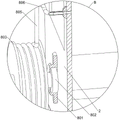
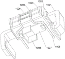
Referring to fig. 1, 2, 3, 13, 14 and 15, the fertilizer adding device 10 is further included, the fertilizer adding device 10 adds fertilizer into the water storage tank 2, the fertilizer adding device 10 includes a fifth support 1001, a storage tank 1002, a blanking pipe 1003, a first guide bar 1004, a first movable frame 1005, a first spring 1006, a baffle 1007, a first contact rod 1008, a chute plate 1009, a second movable frame 1010, a second spring 1011 and a second contact rod 1012, the fifth support 1001 is welded on the left and right sides of the upper portion of the water storage tank 2, the storage tank 1002 is arranged between the two fifth support 1001, the storage tank 1002 can store fertilizer, the storage tank 1002 is located on the top of the water storage tank 2, a square blanking port is opened at the bottom of the storage tank 1002, the blanking pipe 1003 is arranged on the top of the water storage tank 2, and the blanking pipe 1003 faces the bottom of the square blanking port, first guide arm 1004 has been welded to the storage case 1002 rear side, first guide arm 1004 bilateral symmetry slidingtype is provided with first adjustable shelf 1005, the longitudinal symmetry has around having connect first spring 1006 between two first adjustable shelves 1005, two first adjustable shelf 1005 lower parts all are provided with baffle 1007 in opposite side, baffle 1007 is used for blockking up square blanking mouth, two first adjustable shelf 1005 front sides all are provided with first contact bar 1008, the welding of 2 front sides intermediate positions of water storage box has spout board 1009, the gliding style is provided with second adjustable shelf 1010 on the spout board 1009, be connected with second spring 1011 between second adjustable shelf 1010 top and the spout board 1009, second spring 1011 initial state is compression state, the welding of second adjustable shelf 1010 bilateral symmetry has second contact bar 1012, second contact bar 1012 slides downwards and contacts with first contact bar 1008, second contact bar 1012 lower part and the contact of first shell 601 top.
When blueberry roots need to be watered, a worker pours fertilizer into the storage box 1002, when the first shell 601 moves forwards and does not extrude the second contact rod 1012 any more, the second spring 1011 resets to drive the second movable frame 1010 to slide downwards, the second movable frame 1010 slides downwards to drive the second contact rod 1012 to move downwards, the second contact rod 1012 moves downwards to extrude the first contact rod 1008 to move backwards, the first contact rod 1008 moves backwards to drive the first movable frame 1005 to slide backwards, the first spring 1006 is stretched accordingly, the first movable frame 1005 slides backwards to drive the baffle 1007 to move backwards to open the square blanking port, fertilizer in the storage box 1002 falls into the water storage box 2 through the blanking pipe 1003 and is mixed with water, when the first shell 601 moves backwards to reset and extrude the second contact rod 1012, the second contact rod 1012 moves upwards to drive the second movable frame 1010 to slide upwards to reset, the second spring 1011 is compressed accordingly, the second contact rod 1012 moves upwards to no more extrude the first contact rod 1012, the first movable frame 1006 drives the first movable frame 1007 to fall into the square blanking port 2, and the first movable frame 1005 slides towards the square blanking port to block the fertilizer 1005.
Referring to fig. 2, 3, 16, 17 and 18, the fertilizer mixing device further includes a stirring assembly 11, the stirring assembly 11 can fully mix clean water with fertilizer, the stirring assembly 11 includes a second motor 1101, a fifth rotating rod 1102, a second guide bar 1103, a third movable frame 1104, a third spring 1105, a sixth rotating rod 1106, a first clutch block 1107, a stirring frame 1108, a second clutch block 1109 and a third contact rod 1110, the second motor 1101 is disposed at the middle position of the upper portion of the water storage tank 2, the fifth rotating rod 1102 is connected to the output shaft of the second motor 1101 through a coupling, the second guide bar 1103 is welded at the rear side of the top portion of the water storage tank 2 symmetrically, the second guide bar 1103 is located below the second motor 1101, the third movable frame 1104 is disposed between the two second guide bars 1103, bilateral symmetry has around having third spring 1105 between third adjustable shelf 1104 bottom and the water storage box 2 top, third adjustable shelf 1104 intermediate position rotary type is provided with sixth dwang 1106, sixth dwang 1106 and fifth dwang 1102 sliding connection, the welding of sixth dwang 1106 bottom has first separation and reunion piece 1107, rear portion rotary type is provided with stirring frame 1108 in the water storage box 2, stirring frame 1108 can make clear water and fertilizer intensive mixing, water storage box 2 top is run through on stirring frame 1108 top, the welding of stirring frame 1108 top has second separation and reunion piece 1109, second separation and reunion piece 1109 cooperates with first separation and reunion piece 1107, the third adjustable shelf 1104 left and right sides all is provided with third contact bar 1110, third contact bar 1110 contacts with first adjustable shelf 1005.
First movable rack 1005 slides backward and extrudes third contact pole 1110 to drive third movable rack 1104 to slide downward, third spring 1105 is compressed therewith, third movable rack 1104 slides downward to drive sixth dwang 1106 to slide downward on fifth dwang 1102, sixth dwang 1106 slides downward to drive first clutch piece 1107 to move downward and to be engaged with second clutch piece 1109, at this time, the staff starts second motor 1101, the output shaft of second motor 1101 rotates to drive fifth dwang 1102 to rotate, fifth dwang 1102 rotates to drive sixth dwang 1106 to rotate, sixth clutch piece 1106 rotates to drive first clutch piece 1107 to rotate, first clutch piece 1107 rotates to drive second clutch piece 1109 to rotate, second clutch piece 1109 rotates to drive stirring rack 1108 to rotate and to fully mix water with fertilizer, when first movable rack 1005 slides backward and no longer extrudes third dwang contact pole 1110, third spring 1105 resets to drive third movable rack 1104 to slide upward and reset, third movable rack 1104 slides upward to drive third contact pole 110moves upward and resets, third movable rack 1005 slides upward to reset so that third movable rack makes third movable rack 1110 slide upward and to make third dwang contact pole 1110 stop clutch piece 1106 to slide upward and to move upward and to disengage with second clutch piece 1109 again, then second clutch piece 1108 to move upward and to close operation on second clutch piece 1109.
The above description is only an embodiment of the present invention, and not intended to limit the scope of the present invention, and all modifications of equivalent structures and equivalent processes, which are made by the present specification, or directly or indirectly applied to other related technical fields, are included in the scope of the present invention.
Claims (7)
1. The utility model provides a root palpus watering device for blueberry is planted, characterized by includes:
the water storage device comprises a bracket (1), wherein a water storage tank (2) is arranged at the top of the bracket (1);
the ladder (3) is arranged between the left side of the water storage tank (2) and the left side of the top of the bracket (1);
the bottom of the water storage tank (2) is provided with an irrigation component (6) capable of transporting water;
the spray head (4) is arranged on the irrigation component (6), and the spray head (4) can spray water for irrigation;
the water pump (5) is arranged on the irrigation component (6);
the moving component (7) is arranged at the lower part of the irrigation component (6), and the moving component (7) can enable the irrigation component (6) to move;
the irrigation assembly (6) comprises:
the water storage tank comprises a first shell (601), wherein a corrugated pipe (602) is arranged on the rear side of the first shell (601), the top end of the corrugated pipe (602) is communicated with the middle position of the bottom of the water storage tank (2), a water suction pump (5) is positioned in the first shell (601), and the front end of the corrugated pipe (602) is connected with the rear side of the water suction pump (5);
still add subassembly (10) including the fertilizer that can add fertilizer in water storage box (2), fertilizer adds subassembly (10) includes:
the left side and the right side of the upper part of the water storage tank (2) are provided with fifth support frames (1001);
a storage tank (1002) capable of storing fertilizer is arranged between the two fifth support frames (1001), the storage tank (1002) is positioned at the top of the water storage tank (2), and a square blanking port is formed in the bottom of the storage tank (1002);
the water storage tank comprises a blanking pipe (1003), wherein the blanking pipe (1003) is arranged at the top of the water storage tank (2), and the blanking pipe (1003) is opposite to the bottom of the square blanking port;
the first guide rod (1004) is arranged at the rear side of the material storage box (1002);
the first movable frame (1005) is arranged on the first guide rod (1004) in a bilaterally symmetrical sliding manner;
the first springs (1006) are vertically and symmetrically wound between the two first movable frames (1005);
the lower parts of the two first movable frames (1005) are provided with opposite sides with baffles (1007) for blocking the square blanking port;
the front sides of the two first movable frames (1005) are respectively provided with a first contact rod (1008);
the middle position of the front side of the water storage tank (2) is provided with a sliding chute plate (1009);
the second movable frame (1010) is arranged on the sliding groove plate (1009) in a sliding mode;
a second spring (1011), wherein the second spring (1011) is connected between the top of the second movable frame (1010) and the chute plate (1009), and the initial state of the second spring (1011) is a compressed state;
the second contact rod (1012) is arranged on the second movable frame (1010) in bilateral symmetry, the second contact rod (1012) slides downwards to be in contact with the first contact rod (1008), and the lower part of the second contact rod (1012) is in contact with the top of the first shell (601).
2. A root hair irrigation device for blueberry planting as defined in claim 1, wherein the irrigation assembly (6) further comprises:
a water outlet pipe (603) is arranged on the front side of the water suction pump (5);
the front part in the first shell (601) is provided with a first support frame (604);
the rotating pipe (605) is rotatably arranged on the first support frame (604), the end part of the water outlet pipe (603) is contacted with the bottom end of the rotating pipe (605), and the spray head (4) is connected to the top end of the rotating pipe (605).
3. A root hair watering device for blueberry planting as defined in claim 2, wherein the moving assembly (7) comprises:
the middle position of the front side of the bracket (1) is provided with a rail (701);
the second shell (702), the second shell (702) is set at the bottom of the first shell (601);
a second support frame (703), wherein the second support frame (703) is arranged in the second shell (702);
the first motor (704) is arranged at the rear part in the second shell (702), and the first motor (704) is a double-shaft motor;
the rear ends of the left side and the right side of the second supporting frame (703) are respectively and rotatably provided with a first rotating rod (705), and the first rotating rods (705) are connected with the output shafts of the adjacent first motors (704) through couplers;
the front part of the second support frame (703) is rotatably provided with a second rotating rod (706);
and the left end and the right end of the second rotating rod (706) and the back end of the two first rotating rods (705) are respectively provided with a pulley (707), the pulleys (707) are positioned on the outer side of the second shell (702), and the pulleys (707) are connected with the track (701) in a sliding manner.
4. A root hair watering device for blueberry planting as defined in claim 3 further comprising a water inlet assembly (8) for adding water to the reservoir (2), the water inlet assembly (8) comprising:
the third supporting frame (801), the third supporting frame (801) is arranged on the rear side of the water storage tank (2);
a third rotating rod (802) is arranged on the third supporting frame (801) in a rotating mode, and the third rotating rod (802) is arranged on the third supporting frame (801) in a rotating mode;
the pipe winding wheel (803) is arranged on the third rotating rod (802);
a hand wheel (804) is arranged at the rear end of the third rotating rod (802);
a hose (805) around which the hose (805) is wound around the reel (803);
the water storage tank comprises a fixed water inlet pipe (806), the rear side of the upper part of the water storage tank (2) is provided with the fixed water inlet pipe (806), the fixed water inlet pipe (806) is communicated with the water storage tank (2), and the upper end of a hose (805) is communicated with the middle part of the fixed water inlet pipe (806);
immersible pump (807), hose (805) lower extreme is provided with immersible pump (807) that can draw water.
5. A root hair watering device for blueberry planting as defined in claim 4 further comprising a rotating assembly (9) for rotating the rotating tube (605) to increase the spraying range of the spray head (4), wherein the rotating assembly (9) comprises:
the base (901), the middle position of the top of the track (701) is provided with the base (901);
the rack (902) is arranged on the right side of the base (901);
a fourth support frame (903), wherein the front part in the first shell (601) is provided with the fourth support frame (903);
a fourth rotating rod (904) is rotatably arranged on the fourth supporting frame (903), and the bottom end of the fourth rotating rod (904) penetrates through the second shell (702);
a first gear (905) is arranged at the bottom end of the fourth rotating rod (904), and the first gear (905) is matched with the rack (902);
a second gear (906), a third gear (907) is arranged at the lower part of the rotating pipe (605);
a third gear (907), a second gear (906) is arranged at the top end of the fourth rotating rod (904), and the third gear (907) is meshed with the second gear (906).
6. A root hair watering device for blueberry planting according to claim 5 further comprising a stirring assembly (11) for thoroughly mixing clear water and fertilizer, wherein the stirring assembly (11) comprises:
the second motor (1101) is arranged in the middle of the rear side of the upper part of the water storage tank (2);
the output shaft of the second motor (1101) is connected with a fifth rotating rod (1102) through a coupler;
the second guide rod (1103) is symmetrically arranged at the left and right sides of the rear side of the top of the water storage tank (2), and the second guide rod (1103) is positioned below the second motor (1101);
a third movable frame (1104), wherein the third movable frame (1104) is arranged between the two second guide rods (1103) in a sliding manner;
the third spring (1105) is symmetrically wound between the bottom of the third movable frame (1104) and the top of the water storage tank (2) in the left-right direction;
a sixth rotating rod (1106), wherein the sixth rotating rod (1106) is rotatably arranged in the middle of the third movable frame (1104), and the sixth rotating rod (1106) is connected with the fifth rotating rod (1102) in a sliding manner;
the first clutch block (1107) is arranged at the bottom end of the sixth rotating rod (1106);
the stirring frame (1108) capable of fully mixing clean water and fertilizer is rotatably arranged at the inner rear part of the water storage tank (2), and the top end of the stirring frame (1108) penetrates through the top of the water storage tank (2);
the top end of the stirring frame (1108) is provided with a second clutch block (1109), and the second clutch block (1109) is matched with the first clutch block (1107);
the left side and the right side of the third movable frame (1104) are both provided with third contact rods (1110), and the third contact rods (1110) are in contact with the first movable frame (1005).
7. The root hair irrigation device for blueberry planting as defined in claim 4, wherein a rubber sleeve is arranged on the hand wheel (804).
Priority Applications (1)
| Application Number | Priority Date | Filing Date | Title |
|---|---|---|---|
| CN202111612515.3A CN114190149B (en) | 2021-12-27 | 2021-12-27 | A root palpus watering device for blueberry is planted |
Applications Claiming Priority (1)
| Application Number | Priority Date | Filing Date | Title |
|---|---|---|---|
| CN202111612515.3A CN114190149B (en) | 2021-12-27 | 2021-12-27 | A root palpus watering device for blueberry is planted |
Publications (2)
| Publication Number | Publication Date |
|---|---|
| CN114190149A CN114190149A (en) | 2022-03-18 |
| CN114190149B true CN114190149B (en) | 2022-10-04 |
Family
ID=80656636
Family Applications (1)
| Application Number | Title | Priority Date | Filing Date |
|---|---|---|---|
| CN202111612515.3A Active CN114190149B (en) | 2021-12-27 | 2021-12-27 | A root palpus watering device for blueberry is planted |
Country Status (1)
| Country | Link |
|---|---|
| CN (1) | CN114190149B (en) |
Families Citing this family (1)
| Publication number | Priority date | Publication date | Assignee | Title |
|---|---|---|---|---|
| CN114982603B (en) * | 2022-06-21 | 2024-05-17 | 江西省赣州轩辕春秋农业发展有限公司 | Irrigation's navel orange is planted and is driped irrigation device with seedling |
Citations (10)
| Publication number | Priority date | Publication date | Assignee | Title |
|---|---|---|---|---|
| WO2017195924A1 (en) * | 2016-05-10 | 2017-11-16 | 김완수 | Towable multipurpose fertilizer spreader for tractor |
| CN207604312U (en) * | 2017-12-06 | 2018-07-13 | 张晓华 | A automatic remove irrigation equipment for farming |
| CN109006386A (en) * | 2018-08-01 | 2018-12-18 | 陈伟 | A kind of accurate watering device of agricultural planting |
| CN111392128A (en) * | 2020-03-10 | 2020-07-10 | 邱其银 | Plastic bag opening device for watermelon planting |
| CN211931815U (en) * | 2020-04-16 | 2020-11-17 | 抚州源野农牧业发展有限公司 | Water collecting and irrigating device for fruit and vegetable planting |
| CN212753135U (en) * | 2020-09-03 | 2021-03-23 | 刘玺杰 | Accurate device that waters of drought ground economic crop root system |
| CN212876713U (en) * | 2020-08-21 | 2021-04-06 | 吴小清 | Forestry is planted and is used watering equipment |
| CN213306635U (en) * | 2020-06-10 | 2021-06-01 | 福建士维建设有限公司 | Water-saving irrigation device for agricultural planting |
| CN113396755A (en) * | 2021-06-25 | 2021-09-17 | 林建丹 | Agricultural thing networking is with reciprocating type automatic tomato irrigation equipment |
| CN113597863A (en) * | 2021-08-06 | 2021-11-05 | 谢丽梅 | Intelligent agricultural automatic fertilization equipment |
-
2021
- 2021-12-27 CN CN202111612515.3A patent/CN114190149B/en active Active
Patent Citations (10)
| Publication number | Priority date | Publication date | Assignee | Title |
|---|---|---|---|---|
| WO2017195924A1 (en) * | 2016-05-10 | 2017-11-16 | 김완수 | Towable multipurpose fertilizer spreader for tractor |
| CN207604312U (en) * | 2017-12-06 | 2018-07-13 | 张晓华 | A automatic remove irrigation equipment for farming |
| CN109006386A (en) * | 2018-08-01 | 2018-12-18 | 陈伟 | A kind of accurate watering device of agricultural planting |
| CN111392128A (en) * | 2020-03-10 | 2020-07-10 | 邱其银 | Plastic bag opening device for watermelon planting |
| CN211931815U (en) * | 2020-04-16 | 2020-11-17 | 抚州源野农牧业发展有限公司 | Water collecting and irrigating device for fruit and vegetable planting |
| CN213306635U (en) * | 2020-06-10 | 2021-06-01 | 福建士维建设有限公司 | Water-saving irrigation device for agricultural planting |
| CN212876713U (en) * | 2020-08-21 | 2021-04-06 | 吴小清 | Forestry is planted and is used watering equipment |
| CN212753135U (en) * | 2020-09-03 | 2021-03-23 | 刘玺杰 | Accurate device that waters of drought ground economic crop root system |
| CN113396755A (en) * | 2021-06-25 | 2021-09-17 | 林建丹 | Agricultural thing networking is with reciprocating type automatic tomato irrigation equipment |
| CN113597863A (en) * | 2021-08-06 | 2021-11-05 | 谢丽梅 | Intelligent agricultural automatic fertilization equipment |
Also Published As
| Publication number | Publication date |
|---|---|
| CN114190149A (en) | 2022-03-18 |
Similar Documents
| Publication | Publication Date | Title |
|---|---|---|
| CN114190149B (en) | A root palpus watering device for blueberry is planted | |
| CN108887250A (en) | A kind of seedling growth pesticide spraying device | |
| CN112740989A (en) | Watering device for tea planting | |
| CN211268283U (en) | Orchard is planted with spouting medicine device | |
| CN114365731B (en) | Dragon fruit is planted with spouting medicine device | |
| CN215302104U (en) | Agricultural is with mechanical irrigation equipment | |
| CN213603623U (en) | Gardens maintenance is with adding medicine drip irrigation device | |
| CN214592882U (en) | Fertilizer applicator for nursery stock cultivation | |
| CN108243699A (en) | A kind of water and fertilizer irrigation equipment irrigated for garden seedling tree | |
| CN210928626U (en) | Irrigation equipment for fruit tree cultivation | |
| CN210538382U (en) | Self-propelled tobacco field pesticide spraying equipment | |
| CN218302245U (en) | Natural pond liquid dilutes sprinkler | |
| CN211064154U (en) | Liquid manure agitating unit that uses is planted to lemon | |
| CN216533042U (en) | Vegetable planting uses microbial inoculum sprinkler with mixed structure | |
| CN213462971U (en) | Water and fertilizer integrated intelligent irrigation device | |
| CN109644833A (en) | A kind of agricultural production multifunctional trolley | |
| CN216218777U (en) | Fertilizer injection unit of usefulness is planted to cotton | |
| CN216452433U (en) | Afforestation sprinkler for municipal works | |
| CN220674408U (en) | Irrigation equipment for irrigation fertilizer for fruit and vegetable planting | |
| CN214546251U (en) | Water-saving agricultural irrigation equipment | |
| CN220165875U (en) | Automatic nutrient solution adding device for pesticides | |
| CN219628491U (en) | Irrigation mechanism | |
| CN213695414U (en) | Medicine spraying equipment that forestry plant diseases and insect pests were used | |
| CN217770862U (en) | Fertilization and sprinkling irrigation integrated device for planting of sweet broad pea | |
| CN219537265U (en) | Insect pest prevention device for lettuce planting |
Legal Events
| Date | Code | Title | Description |
|---|---|---|---|
| PB01 | Publication | ||
| PB01 | Publication | ||
| SE01 | Entry into force of request for substantive examination | ||
| SE01 | Entry into force of request for substantive examination | ||
| GR01 | Patent grant | ||
| GR01 | Patent grant |