CN113953439A - Automatic matching multi-position rivet pulling device - Google Patents
Automatic matching multi-position rivet pulling device Download PDFInfo
- Publication number
- CN113953439A CN113953439A CN202111402888.8A CN202111402888A CN113953439A CN 113953439 A CN113953439 A CN 113953439A CN 202111402888 A CN202111402888 A CN 202111402888A CN 113953439 A CN113953439 A CN 113953439A
- Authority
- CN
- China
- Prior art keywords
- rivet
- moving assembly
- assembly
- frame
- moving
- Prior art date
- Legal status (The legal status is an assumption and is not a legal conclusion. Google has not performed a legal analysis and makes no representation as to the accuracy of the status listed.)
- Granted
Links
Images


Classifications
-
- B—PERFORMING OPERATIONS; TRANSPORTING
- B21—MECHANICAL METAL-WORKING WITHOUT ESSENTIALLY REMOVING MATERIAL; PUNCHING METAL
- B21J—FORGING; HAMMERING; PRESSING METAL; RIVETING; FORGE FURNACES
- B21J15/00—Riveting
- B21J15/10—Riveting machines
- B21J15/14—Riveting machines specially adapted for riveting specific articles, e.g. brake lining machines
-
- B—PERFORMING OPERATIONS; TRANSPORTING
- B21—MECHANICAL METAL-WORKING WITHOUT ESSENTIALLY REMOVING MATERIAL; PUNCHING METAL
- B21J—FORGING; HAMMERING; PRESSING METAL; RIVETING; FORGE FURNACES
- B21J15/00—Riveting
- B21J15/10—Riveting machines
- B21J15/30—Particular elements, e.g. supports; Suspension equipment specially adapted for portable riveters
- B21J15/32—Devices for inserting or holding rivets in position with or without feeding arrangements
-
- B—PERFORMING OPERATIONS; TRANSPORTING
- B21—MECHANICAL METAL-WORKING WITHOUT ESSENTIALLY REMOVING MATERIAL; PUNCHING METAL
- B21J—FORGING; HAMMERING; PRESSING METAL; RIVETING; FORGE FURNACES
- B21J15/00—Riveting
- B21J15/38—Accessories for use in connection with riveting, e.g. pliers for upsetting; Hand tools for riveting
Landscapes
- Engineering & Computer Science (AREA)
- Mechanical Engineering (AREA)
- Automatic Assembly (AREA)
Abstract
The invention discloses an automatic matching multi-position rivet pulling device which comprises a first door type frame, a second door type frame, a third door type frame, a first moving mechanism, a first rivet pulling mechanism, a second moving mechanism, a second rivet pulling mechanism, a third moving mechanism, a third rivet pulling mechanism, a first rivet placing assembly, a second rivet placing assembly and a third rivet placing assembly. The moving mechanism is used for moving the corresponding rivet pulling mechanism in all directions, so that rivet pulling of boxes in all positions or boxes of different models is achieved, the rivet pulling efficiency of the boxes is improved, meanwhile, in the whole process, only one worker is needed to supervise, and the labor cost is reduced.
Description
Technical Field
The invention belongs to the technical field of transmission box production, and particularly relates to an automatic matching multi-position rivet pulling device.
Background
In order to conveniently install parts on the gearbox body, a rivet with an internal thread is pulled on the gearbox body. In the prior art, the rivet is pulled and riveted on the box body, two workers are adopted to be matched with each other, one person pulls and rivets, one person fixes the angle, the efficiency is low, and the required labor cost is high.
Disclosure of Invention
The invention aims to provide an automatic matching multi-position rivet pulling device which can effectively prevent a transmission box body from falling off downwards under the action of gravity after the transmission box body is clamped.
Therefore, the technical scheme adopted by the invention is as follows: an automatic matching multi-position rivet pulling device comprises a first portal frame, a second portal frame and a third portal frame, the first door type frame extends forwards and backwards and is arranged at the left side, the second door type frame extends leftwards and rightwards and is arranged at the rear side, the third door-shaped frame is arranged at the upper end of the second door-shaped frame, the top of the first door-shaped frame is provided with a first rivet pulling mechanism for pulling and riveting downwards through a first moving mechanism, the top of the second portal frame is provided with a second rivet pulling mechanism which is used for pulling rivets upwards through a second moving mechanism, the top of the third portal frame is provided with a third rivet pulling mechanism for pulling rivets downwards through a third moving mechanism, a first rivet placing component used for taking the first rivet of the first rivet pulling mechanism is arranged on the first door-shaped frame, and a second rivet placing assembly for taking the second rivet from the second rivet pulling mechanism and a third rivet placing assembly for taking the third rivet from the third rivet pulling mechanism are arranged on the third portal frame.
Preferably, the first rivet pulling mechanism, the second rivet pulling mechanism and the third rivet pulling mechanism have the same structure and respectively comprise a rivet pulling gun, the rivet pulling gun is fixedly arranged on a rivet pulling gun mounting plate, and a displacement sensor for determining the downward movement distance of the rivet pulling gun is further arranged on the rivet pulling gun mounting plate.
Preferably, the first moving mechanism comprises a first front-and-back moving assembly and a first up-and-down moving assembly, the first front-and-back moving assembly is arranged at the top of the first door-shaped frame, the first up-and-down moving assembly is arranged on the first front-and-back moving assembly through a first connecting seat, when the first front-and-back moving assembly works, the first front-and-down moving assembly drives the first up-and-down moving assembly and the first rivet pulling mechanism to move back and forth, and the first up-and-down moving assembly drives the first rivet pulling mechanism to move up and down; the second moving mechanism and the third moving mechanism are identical in structure and respectively comprise a left-right moving assembly, a second front-back moving assembly and a second up-down moving assembly, the left-right moving assembly is arranged at the top of the corresponding portal frame, the second front-back moving assembly is arranged on the left-right moving assembly through a second connecting seat, the second up-down moving assembly is arranged on the second front-back moving assembly through a third connecting seat, when the left-right moving assembly works, the corresponding rivet pulling mechanism, the second front-back moving assembly and the second up-down moving assembly are driven to move left and right, when the second front-back moving assembly works, the corresponding rivet pulling mechanism and the second up-down moving assembly are driven to move front and back, and when the second up-down moving assembly acts, the corresponding rivet pulling mechanism is driven to move up and down.
Preferably, a first cross beam is arranged in the middle of the first portal frame, the first rivet placing assembly is arranged on the first cross beam, a third cross beam is arranged on the third portal frame, the third rivet placing assembly is arranged on the third cross beam, and the second rivet placing assembly is arranged in the middle of a right upright post of the third portal frame; the first rivet placing assembly and the third rivet placing assembly are identical in structure and respectively comprise rivet fixing plates arranged on corresponding cross beams, convex-shaped first rivet frames are arranged on the rivet fixing plates, each first rivet frame comprises a rivet receiving part at the upper end and a rivet pushing-out part at the lower end, a first rivet nozzle used for receiving a rivet is vertically and upwards arranged on each rivet receiving part, a first rivet hole is formed in each first rivet nozzle, a rivet groove is formed in each rivet pushing-out part, one side of each rivet groove is communicated with the corresponding first rivet hole, the other side of each rivet groove is located outside the corresponding rivet receiving part, a third telescopic cylinder is arranged on the side face of each rivet pushing-out part, and the third telescopic cylinders are used for pushing the rivets to the other side from one side of the rivet grooves; the second rivet placing assembly comprises a second rivet fixing plate arranged at the middle part of a right side stand column of the third portal frame, the second rivet fixing plate is provided with a second rivet frame, a second rivet nozzle for accepting a rivet is arranged on the second rivet frame, a second rivet hole is formed in the second rivet nozzle, a rivet through hole for the rivet to pass through is formed in the second rivet frame, a circumferential air bag expansion sleeve is arranged in the rivet through hole, when the air bag expansion sleeve is inflated, the upper end of the rivet cannot pass through, and when the air bag is deflated, the rivet passes through the air bag expansion sleeve.
Further preferably, the moving assemblies in each direction on the first moving mechanism, the second moving mechanism and the third moving mechanism are provided with drag chain assemblies.
Further preferably, a bolt mounting assembly for mounting bolts is arranged on the side face of the rivet mounting plate, the bolt mounting assembly comprises a bolt mounting plate arranged on the rivet mounting plate, an up-and-down moving guide rail is vertically arranged on the bolt mounting plate, an up-and-down moving slide block capable of sliding on the up-and-down moving guide rail is arranged on the up-and-down moving guide rail, a wrench seat is arranged on the up-and-down moving slide block, an electric wrench is arranged on the wrench seat, an upper telescopic cylinder and a lower telescopic cylinder are fixedly arranged at the upper end of the bolt mounting plate, and telescopic ends of the upper telescopic cylinder and the lower telescopic cylinder are arranged at the upper end of the wrench seat.
Preferably, the hand riveter adopts a pneumatic hand riveter, and the gas cylinder corresponding to each hand riveter is fixedly arranged on the corresponding moving mechanism through the gas cylinder connecting frame.
Preferably, the first front-back moving assembly, the first up-down moving assembly, the left-right moving assembly, the second front-back moving assembly and the second up-down moving assembly are identical in structure, the left-right moving assembly comprises a moving frame, the moving frame comprises a U-shaped frame, side sealing plates are arranged on two side faces of the U-shaped frame, a sliding rail is arranged above the U-shaped frame and fixed between the sealing plates on two sides, a driving assembly is arranged in the U-shaped frame, a U-shaped sliding block is arranged on the sliding rail, and the driving assembly is a lead screw and nut mechanism.
Further preferably, the first connecting seat and the second connecting seat have the same structure and respectively comprise a horizontal plate and a vertical plate vertically arranged on the horizontal plate, the third connecting seat comprises a first vertical plate and a second vertical plate arranged on the front side of the first vertical plate, and triangular reinforcing plates are respectively arranged between the horizontal plate and the vertical plate and between the first vertical plate and the second vertical plate.
Further preferably, the first door-shaped frame, the second door-shaped frame and the third door-shaped frame are identical in structure and respectively comprise upright columns on the left side and the right side and a top beam arranged at the tops of the upright columns, and through holes for wiring are formed in the upright columns and the top beam.
The invention has the beneficial effects that: during operation, the grabbing robot clamps the box body and then moves, the grabbing robot is close to the first door-shaped frame and the third door-shaped frame and stops at the specified position, then the first rivet pulling mechanism, the second rivet pulling mechanism and the third rivet pulling mechanism are driven by the respective moving mechanisms to move towards the corresponding rivet placing assemblies, then the rivet pulling mechanisms suck the rivets, the moving mechanisms are driven by the various moving mechanisms to move to the corresponding positions of the box body for rivet pulling, two rivet pulling mechanisms are used for rivet pulling downwards, one rivet pulling mechanism is used for rivet pulling upwards, and the moving mechanisms can drive the rivet pulling mechanisms to move towards all directions, so that rivet pulling at all positions of the box body is realized, the rivet pulling efficiency of the box body is improved, meanwhile, in the whole process, only one worker is needed to supervise, and the labor cost is reduced.
Drawings
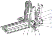
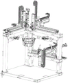
FIG. 1 is a schematic structural diagram of the present invention.
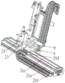
Fig. 2 is a schematic view showing that a third moving mechanism and a third rivet pulling mechanism are installed on a third gate frame according to the present invention.
Fig. 3 is a first schematic view of the first rivet pulling mechanism installed on the first moving mechanism according to the present invention.
Fig. 4 is a second schematic view of the first rivet pulling mechanism installed on the first moving mechanism according to the present invention.
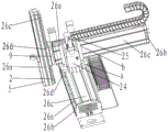
Fig. 5 is a first schematic diagram of a third moving mechanism according to the present invention.
Fig. 6 is a second schematic diagram of a third moving mechanism according to the present invention.
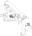
FIG. 7 is a first schematic view of the first rivet placing assembly of the present invention installed in the first gantry.
FIG. 8 is a second schematic view of the first rivet placing assembly of the present invention installed in the first gantry.
FIG. 9 is a schematic view of the second and third rivet placing assemblies of the present invention installed in a third portal frame.
Fig. 10 is a schematic view of the container body placed in the present invention during rivet pulling.
FIG. 11 is a schematic view of a pneumatic rivet feed mechanism (thick line is the air tube carrying the rivets).
Fig. 12 is a schematic view of a dispenser.
Fig. 13 is a schematic view of a dispenser body.
FIG. 14 is a schematic view of the staple dispenser.
FIG. 15 is a schematic view of the staple dispenser body.
FIG. 16 is a schematic view of a first rivet placing assembly (without the first rivet retaining plate).
FIG. 17 is a schematic view of a first rivet holder.
FIG. 18 is a schematic view of a second rivet placing assembly (without the second rivet retaining plate).
FIG. 19 is a schematic view of a second rivet holder.
Detailed Description
The invention will be further illustrated by the following examples in conjunction with the accompanying drawings:
as shown in fig. 1-19, an automatic matching multi-position rivet pulling device is mainly composed of a first door type frame 1, a second door type frame 2, a third door type frame 3, a first moving mechanism a, a first rivet pulling mechanism B, a second moving mechanism C, a second rivet pulling mechanism D, a third moving mechanism E, a third rivet pulling mechanism F, a first rivet placing assembly G, a second rivet placing assembly H and a third rivet placing assembly J, wherein the first door type frame 1 is arranged on the left side in a front-back extending mode, the second door type frame 2 is arranged on the rear side in a left-right extending mode, the third door type frame 3 is arranged at the upper end of the second door type frame 2 and integrally forms a 7-shaped frame, and therefore a grabbing robot can conveniently grab a box body to move to a corresponding position and then rivet.
The riveting device comprises a first door type frame 1, a second door type frame 3, a third door type frame and a first moving mechanism A, wherein the first moving mechanism A is arranged at the top of the first door type frame 1, the first moving mechanism A is arranged at the top of the first door type frame, the second moving mechanism A is arranged at the top of the second door type frame, the second moving mechanism C is arranged at the top of the second door type frame, the second moving mechanism D is arranged at the top of the second door type frame, the third moving mechanism E is arranged at the top of the third door type frame, the third moving mechanism F is arranged at the top of the third door type frame, the third moving mechanism E is arranged at the top of the third door type frame, each pulling and riveting mechanism can move, and therefore pulling and riveting of boxes with different specifications is achieved. Meanwhile, for facilitating automatic nail feeding, a first rivet placing assembly G for taking the nails by the first rivet pulling mechanism B is arranged on the first portal frame 3, and a second rivet placing assembly H for taking the nails by the second rivet pulling mechanism D and a third rivet placing assembly J for taking the nails by the third rivet pulling mechanism F are arranged on the third portal frame 3.
The first rivet pulling mechanism B, the second rivet pulling mechanism D and the third rivet pulling mechanism F are identical in structure and respectively comprise a rivet pulling gun 4, the rivet pulling gun 4 is fixedly arranged on a rivet pulling gun mounting plate 5, and a displacement sensor 6 used for determining the downward moving distance of the rivet pulling gun 4 is further arranged on the rivet pulling gun mounting plate 5. The displacement sensor 6 can adopt a contact type or a laser type, when the contact type is adopted, a sensor telescopic cylinder used for the displacement sensor to move up and down needs to be arranged at the upper end of the displacement sensor, the rivet pulling of different boxes and different positions of the boxes is convenient to realize, the laser type displacement sensor is preferably adopted, and the structure is simple and reliable.
Preferably, the hand riveter 4 is a pneumatic hand riveter, and the gas cylinder 24 corresponding to each hand riveter 4 is fixedly arranged on the corresponding moving mechanism through the gas cylinder connecting frame 25, so that the length of the gas pipe can be reduced.
The first moving mechanism A specifically comprises a first front-and-back moving assembly and a first up-and-down moving assembly, the first front-and-back moving assembly is arranged at the top of the first door type frame 1, the first up-and-down moving assembly is arranged on the first front-and-back moving assembly through a first connecting seat 7, the first front-and-back moving assembly drives the first up-and-down moving assembly and the first rivet pulling mechanism B to move back and forth when working, and the first up-and-down moving assembly drives the first rivet pulling mechanism B to move up and down when working.
The second moving mechanism C and the third moving mechanism E are identical in structure and respectively comprise a left-right moving assembly, a second front-back moving assembly and a second up-down moving assembly, the left-right moving assembly is arranged at the top of the corresponding portal frame, the second front-back moving assembly is arranged on the left-right moving assembly through a second connecting seat 8, the second up-down moving assembly is arranged on the second front-back moving assembly through a third connecting seat 9, when the left-right moving assembly works, the corresponding rivet pulling mechanism is driven, the second front-back moving assembly and the second up-down moving assembly move left-right, when the second front-back moving assembly works, the corresponding rivet pulling mechanism and the second up-down moving assembly are driven to move front-back, and when the second up-down moving assembly acts, the corresponding rivet pulling mechanism is driven to move up-down. The left-right moving assembly is not arranged on the first moving mechanism, so that the stroke interference of the first rivet pulling mechanism and the second rivet pulling mechanism or the third rivet pulling mechanism during movement can be effectively prevented, and the calculation amount of the central processor can be reduced.
The gas cylinder connecting frame 25 of the first rivet pulling mechanism is arranged on the rear side face of the first connecting seat 7, the gas cylinder connecting frame 25 of the second rivet pulling mechanism is arranged on the right side face of the second connecting seat 8, and the gas cylinder connecting frame 25 of the third rivet pulling mechanism is also arranged on the left side face of the third connecting seat 8.
First connecting seat 7 is the same with the structure of second connecting seat 8, all includes horizontal plate an and vertical board b of setting on horizontal plate a, and third connecting seat 9 includes first riser 9a and sets up the second riser 9b in first riser 9a front side, all is provided with the triangle-shaped reinforcing plate between horizontal plate a and the vertical board b, between first riser 9a and the second riser 9 b.
The first front-back moving assembly, the first up-down moving assembly, the left-right moving assembly, the second front-back moving assembly and the second up-down moving assembly are identical in structure, the left-right moving assembly comprises a moving frame 26, the moving frame 26 comprises a U-shaped frame 26a, side sealing plates 26b are arranged on two side faces of the U-shaped frame 26a, a sliding rail 26c is arranged above the U-shaped frame 26a, the sliding rail 26c is fixed between the sealing plates 26b on the two sides, a driving assembly is arranged in the U-shaped frame 26a, a U-shaped sliding block 26d is arranged on the sliding rail 26c, and the driving assembly is a screw rod nut mechanism.
Specifically, the U-shaped frame 26a of the first front-and-back moving assembly is fixed at the top of the first door-shaped frame 1, the U-shaped slider 26d of the first front-and-back moving assembly is fixed with the first connecting seat 7, the U-shaped slider 26d of the first up-and-down moving assembly is fixed on the first connecting seat 7, the U-shaped frame 26a of the left-and-right moving assembly is fixed at the top of the third door-shaped frame 3, the U-shaped slider 26d of the left-and-right moving assembly is fixed with the second connecting seat 8, the U-shaped slider 26d of the second front-and-back moving assembly is fixed on the second connecting seat 8, the U-shaped frame 26a of the second front-and-back moving assembly is fixed with the third connecting seat 9, the U-shaped slider 26d of the second up-and-down moving assembly is fixed with the corresponding rivet pulling mechanisms on the U-shaped frame 26a of the first up-and-down moving assembly and the U-shaped frame 26a of the second up-and-down moving assembly.
And the moving assemblies in each direction on the first moving mechanism A, the second moving mechanism B and the third moving mechanism E are provided with drag chain assemblies. The first front-back moving assembly and the drag chain assembly of the left-right moving assembly are provided with drag chain discs at the tops of the door-shaped frames, one ends of the drag chains are fixed on the drag chain discs, and the other ends of the drag chains are fixed on the corresponding connecting seats through supports. One end of a drag chain of the first up-and-down moving assembly, the second up-and-down moving assembly and the second up-and-down moving assembly is arranged on the corresponding U-shaped frame 26a through a support, and the other end of the drag chain is also arranged on the corresponding connecting seat through a support. The electric wire or the air pipe is arranged in the drag chain, so that the whole device is tidy, and the electric wire and the air pipe cannot be wound, thereby reducing the safety risk.
The middle part of first door type frame 1 is provided with first crossbeam 10, and first rivet is placed subassembly G and is set up on first crossbeam 10, and third door type frame 3 is provided with third crossbeam 11, and the subassembly J setting is placed on the third crossbeam to the third rivet, and the subassembly H setting is placed at the right side stand middle part of third door type frame 3 to the second rivet.
The first rivet placing component G and the third rivet placing component J are identical in structure and comprise first rivet fixing plates 12 arranged on corresponding cross beams, first rivet frames 13 in a convex shape are arranged on the first rivet fixing plates 12, each first rivet frame 13 comprises a rivet receiving portion 13a at the upper end and a rivet pushing portion 13b at the lower end, a first rivet nozzle 14 used for receiving a rivet is vertically and upwards arranged on each rivet receiving portion 13a, a first rivet hole 14a is formed in each first rivet nozzle 14, a rivet groove 13c is formed in each rivet pushing portion 13b, one side of each rivet groove 13c is communicated with the corresponding first rivet hole 14a, the other side of each rivet receiving portion 13a is located outside the corresponding rivet receiving portion, a third telescopic cylinder 15 is arranged on the side face of each rivet pushing portion 13b, and each third telescopic cylinder 15 is used for pushing the rivet to the other side of the corresponding rivet groove 13 c. In order to prevent the rivet from falling down in the rivet groove 13c, a first annular air bag is arranged in the rivet groove 13c, when the rivet falls into the first annular air bag in the rivet groove along the first rivet hole, the rivet moves to the other side of the rivet groove under the action of the third telescopic cylinder for picking up.
The second rivet placing assembly H comprises a second rivet fixing plate 16 arranged in the middle of a right side upright post of the third portal frame 3, a second rivet frame 17 is arranged on the second rivet fixing plate 16, a second rivet nozzle for receiving a rivet is arranged on the second rivet frame 17, a second rivet hole is formed in the second rivet nozzle, a rivet through hole 17a for the rivet to pass through is formed in the second rivet frame 17, the second rivet hole is located right above the rivet through hole 17a and is identical to the rivet through hole, a second annular air bag is arranged in the rivet through hole 17a, when the second annular air bag is inflated, the upper end of the rivet cannot pass through, and when the second annular air bag is deflated, the rivet passes through the second annular air bag.
In order to realize automatic feeding, the first rivet nozzle and the second rivet nozzle are communicated with a rivet feeding mechanism, and a sensor for determining whether rivets exist is arranged on each rivet placing component. Pneumatic rivet feeding mechanism. The rivet sorting device comprises a sorting device K, a distributor L and a rivet distributor M, wherein the sorting device K is used for sorting rivets, the distributor L is used for distributing the rivets in the same direction to different positions, the rivet distributor M is used for converting the rivet direction, and the rivet distributor M is located between the sorting device K and the distributor L. The sorting device K is a prior art and is not described herein.
The distributor L specifically comprises a distributor main body 27, a distribution groove 27a for rivets to move left and right is arranged in the distributor main body 27, a third annular air bag 28 is arranged in the distribution groove 27a, a second nail feeding nozzle 29 is arranged on the top surface of the distributor main body 27, a second nail feeding hole 29a communicated with the distribution groove 27a is arranged in the second nail feeding nozzle 29, at least two distribution nail discharging nozzles 30 are arranged on the bottom surface of the distributor main body 27 at left and right intervals, distribution nail discharging holes communicated with the distribution groove 27a are arranged in the distribution nail discharging nozzles 30, a distribution air blowing nozzle 31 used for blowing air to the distribution nail discharging holes is arranged on each distribution nail discharging nozzle 30, a second telescopic cylinder 33 used for pushing the rivets to move left and right in the distribution groove 27a is arranged at the right end of the distributor main body 27 through a second telescopic cylinder mounting seat 32, and the third annular air bag 28 is connected with the telescopic end of the second telescopic cylinder 33. The third annular air bag 28 is used for preventing the rivets from falling down in the distribution groove 27a, and when the third annular air bag 28 is inflated, the rivets can be prevented from entering the distribution nail holes, so that the rivets can move left and right in the distribution groove 27a, and when the air in the third annular air bag 28 is exhausted, the rivets can enter the distribution nail holes.
The specific structure of the nail distributor C comprises a nail distributor main body 35, a nail distributing groove 35a for the left and right movement of the rivets is horizontally arranged in the nail distributor main body 35, a fourth annular air bag 36 is arranged in the nail distributing groove 35a, a forward nail outlet 37 and a first nail inlet 38 are arranged on the top surface of the nail distributor main body 35 at left and right intervals, a first nail inlet hole 38a communicated with the middle of the nail distributing groove 35a is arranged in the first nail inlet 38, a forward nail outlet hole 37a communicated with the left end of the nail distributing groove 35a is arranged in the forward nail outlet 37, a reverse nail outlet 39 is arranged on the bottom surface of the nail distributor main body 35, a reverse nail outlet hole communicated with the right end of the nail distributing groove 35a is arranged in the reverse nail outlet 39, a first telescopic cylinder 41 for driving the left and right movement of the rivets in the nail distributing groove 35a is arranged at the right end of the nail distributor main body 35 through a first telescopic cylinder mounting seat 40, the fourth annular air bag 36 is connected with the telescopic end of the first telescopic cylinder 41, the top surface of the nail splitter main body 35 is provided with a reverse blowing nozzle 42 used for blowing air to the reverse nail outlet hole, the bottom surface of the nail splitter main body 35 is provided with a forward blowing nozzle 43 used for blowing air to the forward nail outlet hole 37a, and the second nail inlet nozzle 29 is connected with either the forward nail outlet nozzle 37 or the reverse nail outlet nozzle 39. The fourth annular air bag 36 is used for preventing the rivet from falling down in the nail separating groove 35a, and when the fourth annular air bag 36 is inflated, the rivet can be prevented from entering the forward nail outlet 37a or the reverse nail outlet, so that the rivet can move left and right in the nail separating groove 35a, and when the air in the fourth annular air bag 36 is exhausted, the rivet can enter the forward nail outlet 37a or the reverse nail outlet.
The discharge port of the sequencing device K is connected with the first nail feeding nozzle 38 through an air pipe, the discharge port of the sequencing device K is provided with a discharge blowing nozzle 34, and the first nail feeding nozzle 38 is connected with the second nail feeding nozzle 29 through an air pipe.
The movement process of the rivets in the pneumatic rivet feeding mechanism is as follows: after the rivets are sequenced by the sequencing device, the rivets arrive at the discharge hole, the big ends of the rivets face upwards, the rivets enter the first rivet inlet nozzle along the air pipe under the action of the discharge blow nozzle, then fall into the fourth annular air bag positioned in the distribution groove along the first rivet inlet hole, the rivets move to the position under the forward rivet outlet hole or the position over the reverse rivet outlet hole under the action of the first telescopic cylinder, then the fourth annular air bag exhausts air, meanwhile, the corresponding forward blow nozzle or reverse blow nozzle works, the rivets are blown into the corresponding forward rivet outlet nozzle or reverse rivet outlet nozzle, enter the second rivet inlet nozzle along the corresponding air pipe, then fall into the third annular air bag in the distribution groove along the second rivet inlet hole, the rivets move to the position over the distribution rivet outlet hole under the action of the second telescopic cylinder, then the third annular air bag exhausts air, and the rivets fall into the corresponding distribution outlet hole, then under the action of a distribution blowing nozzle, the rivet is enabled to reach the corresponding rivet placing assembly along the air pipe.
The bolt installation assembly for installing the bolt is arranged on the side face of the rivet installation plate 5 and comprises a bolt installation plate 18 arranged on the rivet installation plate 5, an up-and-down moving guide rail 19 is vertically arranged on the bolt installation plate 18, an up-and-down moving slide block 20 capable of sliding on the up-and-down moving guide rail 19 is arranged on the up-and-down moving guide rail 19, a wrench seat 21 is arranged on the up-and-down moving slide block 20, an electric wrench 22 is arranged on the wrench seat 21, an upper telescopic cylinder 23 and a lower telescopic cylinder 23 are fixedly arranged at the upper end of the bolt installation plate 18, and the telescopic ends of the upper telescopic cylinder 23 and the lower telescopic cylinder 23 are arranged at the upper end of the wrench seat 21. The equipment can not only be used for rivet pulling, but also can realize the tightening of the bolt.
First door type frame 1, second door type frame 2 and third door type frame 3's structure is the same, all includes the stand c of the left and right sides and sets up the back timber d at stand c top, is provided with the through-hole that is used for walking the line in stand c and the back timber d, is favorable to whole device clean and tidy, can protect the electric wire to a certain extent simultaneously.
The during operation, whether sensor discernment has the rivet on the subassembly is placed to the rivet, if do not then pneumatic rivet feeding mechanism transports the rivet to the subassembly is placed to the rivet, it moves and is close to and stop in assigned position department to first door type frame and third door type frame after the box is held to the snatching robot simultaneously, treat that the rivet is placed to the rivet on the subassembly after, each rivet mechanism moves towards the rivet that corresponds and place the subassembly and move under respective moving mechanism's drive, then rivet mechanism holds the rivet, it carries out the rivet to move the box and correspond position department under various moving mechanism drives. Through grabbing the robot rotation, can realize the rivet of each angle of box.
Claims (8)
1. The utility model provides an automatic match multiposition rivet device which characterized in that: the riveting device comprises a first door type frame (1), a second door type frame (2) and a third door type frame (3), wherein the first door type frame (1) is arranged on the left side in a front-back extending mode, the second door type frame (2) is arranged on the rear side in a left-right extending mode, the third door type frame (3) is arranged at the upper end of the second door type frame (2), a first rivet pulling mechanism (B) for downward rivet pulling is arranged at the top of the first door type frame (1) through a first moving mechanism (A), a second rivet pulling mechanism (D) for upward rivet pulling is arranged at the top of the second door type frame (2) through a second moving mechanism (C), a third rivet pulling mechanism (F) for downward rivet pulling is arranged at the top of the third door type frame (3) through a third moving mechanism (E), and a first rivet placing assembly (G) for taking rivets by the first rivet pulling mechanism (B) is arranged on the first door type frame (3), a second rivet placing assembly (H) for taking a second rivet by a second rivet pulling mechanism (D) and a third rivet placing assembly (J) for taking a third rivet by a third rivet pulling mechanism (F) are arranged on the third portal frame (3);
the first rivet pulling mechanism (B), the second rivet pulling mechanism (D) and the third rivet pulling mechanism (F) are identical in structure and respectively comprise a rivet pulling gun (4), the rivet pulling gun (4) is fixedly arranged on a rivet pulling gun mounting plate (5), and a displacement sensor (6) used for determining the downward moving distance of the rivet pulling gun (4) is further arranged on the rivet pulling gun mounting plate (5);
the first moving mechanism (A) comprises a first front-and-back moving assembly and a first up-and-down moving assembly, the first front-and-back moving assembly is arranged at the top of the first door-shaped frame (1), the first up-and-down moving assembly is arranged on the first front-and-back moving assembly through a first connecting seat (7), when the first front-and-back moving assembly works, the first up-and-down moving assembly and the first rivet pulling mechanism (B) are driven to move back and forth, and the first up-and-down moving assembly works to drive the first rivet pulling mechanism (B) to move up and down; the second moving mechanism (C) and the third moving mechanism (E) are identical in structure and respectively comprise a left-right moving assembly, a second front-back moving assembly and a second up-down moving assembly, the left-right moving assembly is arranged at the top of the corresponding portal frame, the second front-back moving assembly is arranged on the left-right moving assembly through a second connecting seat (8), the second up-down moving assembly is arranged on the second front-back moving assembly through a third connecting seat (9), when the left-right moving assembly works, the corresponding rivet pulling mechanism, the second front-back moving assembly and the second up-down moving assembly are driven to move left and right, when the second front-back moving assembly works, the corresponding rivet pulling mechanism and the second up-down moving assembly are driven to move front and back, and when the second up-down moving assembly works, the corresponding rivet pulling mechanism is driven to move up and down.
2. The auto-mating multi-position blind rivet apparatus of claim 1, further characterized by: a first cross beam (10) is arranged in the middle of the first portal frame (1), the first rivet placing assembly (G) is arranged on the first cross beam (10), a third cross beam (11) is arranged on the third portal frame (3), the third rivet placing assembly (J) is arranged on the third cross beam, and the second rivet placing assembly (H) is arranged in the middle of a right upright post of the third portal frame (3); the first rivet placing component (G) and the third rivet placing component (J) are identical in structure and respectively comprise a first rivet fixing plate (12) arranged on a corresponding cross beam, a first rivet frame (13) in a convex shape is arranged on the first rivet fixing plate (12), the first rivet frame (13) comprises a rivet receiving part (13a) at the upper end and a rivet pushing-out part (13b) at the lower end, a first rivet nozzle (14) used for receiving a rivet is vertically and upwards arranged on the rivet receiving part (13a), a first rivet hole (14a) is arranged in the first rivet nozzle (14), a rivet groove (13c) is arranged on the rivet pushing-out part (13b), one side of the rivet groove (13c) is communicated with the first rivet hole (14a), the other side of the rivet receiving part (13a) is arranged outside the rivet receiving part, and a third telescopic cylinder (15) is arranged on the side of the rivet pushing-out part (13b), the third telescopic cylinder (15) is used for pushing the rivet from one side of the rivet groove (13c) to the other side; the second rivet placing assembly (H) comprises a second rivet fixing plate (16) arranged at the middle part of a right side stand column of a third door-shaped frame (3), a second rivet frame (17) is arranged on the second rivet fixing plate (16), the second rivet frame (17) is used for a rivet through hole through which a rivet passes, a circumferential airbag expansion sleeve is arranged in the rivet through hole, when the airbag expansion sleeve is inflated, the upper end of the rivet cannot pass, and when the rivet is deflated, the airbag expansion sleeve is passed through.
3. The auto-mating multi-position blind rivet apparatus of claim 1, further characterized by: and the moving assemblies in each direction on the first moving mechanism (A), the second moving mechanism (B) and the third moving mechanism (E) are provided with drag chain assemblies.
4. The auto-mating multi-position blind rivet apparatus of claim 1, further characterized by: the rivet is characterized in that a bolt mounting assembly used for mounting bolts is arranged on the side face of the rivet mounting plate (5), the bolt mounting assembly comprises a bolt mounting plate (18) arranged on the rivet mounting plate (5), an up-and-down moving guide rail (19) is vertically arranged on the bolt mounting plate (18), an up-and-down moving slider (20) capable of sliding on the up-and-down moving guide rail (19) is arranged on the up-and-down moving guide rail (19), a wrench seat (21) is arranged on the up-and-down moving slider (20), an electric wrench (22) is arranged on the wrench seat (21), an upper telescopic cylinder (23) and a lower telescopic cylinder (23) are fixedly arranged at the upper end of the bolt mounting plate (18), and a telescopic end of the upper telescopic cylinder (23) and a telescopic end of the lower telescopic cylinder (23) are arranged at the upper end of the wrench seat (21).
5. The auto-mating multi-position blind rivet apparatus of claim 1, further characterized by: the hand riveter (4) adopts a pneumatic hand riveter, and the air bottle (24) corresponding to each hand riveter (4) is fixedly arranged on the corresponding moving mechanism through an air bottle connecting frame (25).
6. The auto-mating multi-position blind rivet apparatus of claim 1, further characterized by: the structure of the first front-back moving assembly, the first up-down moving assembly, the left-right moving assembly, the second front-back moving assembly and the second up-down moving assembly is the same, the left-right moving assembly comprises a moving frame (26), the moving frame (26) comprises a U-shaped frame (26a), side sealing plates (26b) are arranged on two side faces of the U-shaped frame (26a), a sliding rail (26c) is arranged above the U-shaped frame (26a), the sliding rail (26c) is fixed between the sealing plates (26b) on two sides, a driving assembly is arranged in the U-shaped frame (26a), a U-shaped sliding block (26d) is arranged on the sliding rail (26c), and the driving assembly is a screw rod nut mechanism.
7. The auto-mating multi-position blind rivet apparatus of claim 1, further characterized by: the structure of first connecting seat (7) is the same with second connecting seat (8), all includes horizontal plate (a) and vertical board (b) of vertical setting on horizontal plate (a), third connecting seat (9) include first riser (9a) and set up second riser (9b) in first riser (9a) front side, all be provided with the triangle-shaped reinforcing plate between horizontal plate (a) and vertical board (b), between first riser (9a) and second riser (9 b).
8. The auto-mating multi-position blind rivet apparatus of claim 1, further characterized by: the structure of first door type frame (1), second door type frame (2) and third door type frame (3) is the same, all includes stand (c) and the back timber (d) of setting at stand (c) top of the left and right sides, be provided with the through-hole that is used for walking the line in stand (c) and back timber (d).
Priority Applications (1)
| Application Number | Priority Date | Filing Date | Title |
|---|---|---|---|
| CN202111402888.8A CN113953439B (en) | 2021-11-24 | 2021-11-24 | Automatic matching multi-position rivet pulling device |
Applications Claiming Priority (1)
| Application Number | Priority Date | Filing Date | Title |
|---|---|---|---|
| CN202111402888.8A CN113953439B (en) | 2021-11-24 | 2021-11-24 | Automatic matching multi-position rivet pulling device |
Publications (2)
| Publication Number | Publication Date |
|---|---|
| CN113953439A true CN113953439A (en) | 2022-01-21 |
| CN113953439B CN113953439B (en) | 2023-03-28 |
Family
ID=79471798
Family Applications (1)
| Application Number | Title | Priority Date | Filing Date |
|---|---|---|---|
| CN202111402888.8A Active CN113953439B (en) | 2021-11-24 | 2021-11-24 | Automatic matching multi-position rivet pulling device |
Country Status (1)
| Country | Link |
|---|---|
| CN (1) | CN113953439B (en) |
Citations (11)
| Publication number | Priority date | Publication date | Assignee | Title |
|---|---|---|---|---|
| CN207205161U (en) * | 2017-07-26 | 2018-04-10 | 广州瑞松智能科技股份有限公司 | A kind of elevator floor door plate rivet pulling device |
| CN207655830U (en) * | 2017-12-25 | 2018-07-27 | 上海闳铖自动化技术有限公司 | A kind of full-automatic nut riveting mechanism |
| CN108819273A (en) * | 2018-06-25 | 2018-11-16 | 宁波丞达精机有限公司 | A kind of thin plate automatic rivet pulling equipment and processing method |
| CN208408437U (en) * | 2018-06-25 | 2019-01-22 | 宁波丞达精机有限公司 | A kind of servo motor driving rivet pulling device |
| CN208593093U (en) * | 2018-06-25 | 2019-03-12 | 宁波丞达精机有限公司 | A kind of thin plate automatic rivet pulling equipment |
| CN208992134U (en) * | 2018-08-29 | 2019-06-18 | 苏州智联科慧自动化有限公司 | A kind of thread bush staking mechanism |
| CN209110489U (en) * | 2018-11-19 | 2019-07-16 | 南京中拓科技有限公司 | A kind of lock core inspection and button assembling mechanism for automobile safety belt mortise lock |
| CN110586838A (en) * | 2019-09-09 | 2019-12-20 | 上海友升铝业有限公司 | Automatic rivet pulling machine of replaceable battery frame of rivet pulling gun |
| CN210966821U (en) * | 2019-09-09 | 2020-07-10 | 上海友升铝业有限公司 | Automatic rivet pulling machine for battery frame with transverse floating return mechanism of rivet pulling gun |
| CN211727362U (en) * | 2019-11-01 | 2020-10-23 | 广州市力宏自动化设备有限公司 | Special equipment for assembling automobile chassis oil pipe and riveting iron protection plate |
| CN214053560U (en) * | 2020-11-20 | 2021-08-27 | 上海创志实业有限公司 | Double-gun full-automatic rivet pulling tool |
-
2021
- 2021-11-24 CN CN202111402888.8A patent/CN113953439B/en active Active
Patent Citations (11)
| Publication number | Priority date | Publication date | Assignee | Title |
|---|---|---|---|---|
| CN207205161U (en) * | 2017-07-26 | 2018-04-10 | 广州瑞松智能科技股份有限公司 | A kind of elevator floor door plate rivet pulling device |
| CN207655830U (en) * | 2017-12-25 | 2018-07-27 | 上海闳铖自动化技术有限公司 | A kind of full-automatic nut riveting mechanism |
| CN108819273A (en) * | 2018-06-25 | 2018-11-16 | 宁波丞达精机有限公司 | A kind of thin plate automatic rivet pulling equipment and processing method |
| CN208408437U (en) * | 2018-06-25 | 2019-01-22 | 宁波丞达精机有限公司 | A kind of servo motor driving rivet pulling device |
| CN208593093U (en) * | 2018-06-25 | 2019-03-12 | 宁波丞达精机有限公司 | A kind of thin plate automatic rivet pulling equipment |
| CN208992134U (en) * | 2018-08-29 | 2019-06-18 | 苏州智联科慧自动化有限公司 | A kind of thread bush staking mechanism |
| CN209110489U (en) * | 2018-11-19 | 2019-07-16 | 南京中拓科技有限公司 | A kind of lock core inspection and button assembling mechanism for automobile safety belt mortise lock |
| CN110586838A (en) * | 2019-09-09 | 2019-12-20 | 上海友升铝业有限公司 | Automatic rivet pulling machine of replaceable battery frame of rivet pulling gun |
| CN210966821U (en) * | 2019-09-09 | 2020-07-10 | 上海友升铝业有限公司 | Automatic rivet pulling machine for battery frame with transverse floating return mechanism of rivet pulling gun |
| CN211727362U (en) * | 2019-11-01 | 2020-10-23 | 广州市力宏自动化设备有限公司 | Special equipment for assembling automobile chassis oil pipe and riveting iron protection plate |
| CN214053560U (en) * | 2020-11-20 | 2021-08-27 | 上海创志实业有限公司 | Double-gun full-automatic rivet pulling tool |
Also Published As
| Publication number | Publication date |
|---|---|
| CN113953439B (en) | 2023-03-28 |
Similar Documents
| Publication | Publication Date | Title |
|---|---|---|
| CN216263306U (en) | Automatic match multiposition rivet pulling device | |
| CN107089489B (en) | Take charactron discharging machine of automated inspection and direction of rotation function | |
| CN102642718B (en) | Track sucking disk type gripping device | |
| CN201366685Y (en) | Automatic screw fastening machine | |
| CN110355106B (en) | Bolt and screw rod length screening device | |
| CN105903723A (en) | Automatic dust removal equipment for electric energy meters | |
| CN113953439B (en) | Automatic matching multi-position rivet pulling device | |
| CN204638784U (en) | A kind of plates of automobile fast repair drawing combined tool | |
| CN110026358A (en) | IC chip test braider substandard products collection device and method | |
| CN106239565B (en) | Automatic boxing truss manipulator | |
| CN111266516A (en) | Rivet autoloading riveting device | |
| CN218906189U (en) | Transparent pipe mouth of a river guillootine | |
| CN102329178B (en) | Automatic waist-clamping machine for detonators | |
| CN202131240U (en) | Automatic middle clamping device for detonators | |
| CN2300461Y (en) | Multiple straight pipe cold drawing machine | |
| CN214348316U (en) | Cleaning device | |
| CN103862204A (en) | Automobile bumper grabbing mechanism | |
| CN110640072B (en) | Cartridge clip type nail feeding mechanism of flow drill screwing equipment | |
| CN212264215U (en) | Copper pipe vertical pulling machine | |
| CN209623650U (en) | Axis outer diameter automatic detecting machine | |
| CN102529904B (en) | Pulling tower for automobile metal plate maintenance and stretching method thereof | |
| US3426563A (en) | Peening apparatus | |
| CN206939807U (en) | A kind of charactron automatic discharge machine with discharge device | |
| CN206327914U (en) | Turbine rechecks system | |
| CN206985649U (en) | A kind of system for automobile tire maintenance |
Legal Events
| Date | Code | Title | Description |
|---|---|---|---|
| PB01 | Publication | ||
| PB01 | Publication | ||
| SE01 | Entry into force of request for substantive examination | ||
| SE01 | Entry into force of request for substantive examination | ||
| GR01 | Patent grant | ||
| GR01 | Patent grant |