Disclosure of Invention
The invention aims to provide a tunnel air supply system based on oxygen-enriched air storage and oxygenation, which is used for long-distance air supply to a long tunnel with multiple working surfaces, can effectively prolong the limit ventilation length of a push-in ventilation system and provides a clean oxygen-enriched environment for a construction area.
The technical scheme adopted by the invention is as follows: the tunnel air supply system based on oxygen-enriched air storage and oxygenation comprises an inclined shaft and a plurality of positive holes, wherein the inclined shaft is directly communicated with the positive holes close to the inclined shaft, and the adjacent positive holes are communicated through a plurality of transverse channels which are arranged at intervals; among the plurality of transverse channels, the transverse channel at the intersection of the centering inclined shaft and the positive hole is a connecting channel, the transverse channel close to the palm surface is an auxiliary channel, and the transverse channel between the connecting channel and the auxiliary channel is plugged by a wind shielding wall;
one positive hole is a wind storage tunnel, and the rest is a conventional hole;
an oxygen-enriched air bin is arranged in the air storage tunnel, one end of the oxygen-enriched air bin, which faces the tunnel face, is an outlet end, and the other end of the oxygen-enriched air bin is an inlet end;
the device is provided with a ventilation device for introducing fresh air into the oxygen-enriched air bin, and the ventilation device passes through the connection channel along the inclined shaft and is connected with the oxygen-enriched air bin through the inlet end of the oxygen-enriched air bin;
an air supply pipeline for sending fresh air in the oxygen-enriched air bin into the tunnel face of each tunnel is arranged, one end of the air supply pipeline is connected with the oxygen-enriched air bin through an outlet of the oxygen-enriched air bin, and the other end of the air supply pipeline extends to the vicinity of the tunnel face of each tunnel;
an oxygen supply device for supplying oxygen is arranged outside the oxygen-enriched air bin, and the oxygen supply device is communicated with the oxygen-enriched air bin.
Furthermore, the two sets of oxygen supply devices are arranged on two sides of the positive hole along the transverse direction of the positive hole; each set of oxygen supply device comprises a low-temperature liquid oxygen storage tank, gasification equipment and an air compressor which are connected in sequence; the air compressors of the oxygen supply devices are connected with the oxygen-enriched air bin through oxygen supply pipelines.
Further, an oxygen diffusion device is arranged in the oxygen-enriched air bin, the oxygen diffusion device comprises an annular oxygen diffusion pipe, the oxygen diffusion pipe is arranged at the inlet end of the oxygen-enriched air bin, and an oxygen supply pipeline passes through the inlet end of the oxygen-enriched air bin and is communicated with the oxygen diffusion pipe; and air distribution holes are uniformly distributed on one side of the oxygen diffusion pipe, which is aligned to the outlet end of the oxygen-enriched air bin, along the circumferential direction of the oxygen diffusion pipe, and an oxygen diffuser is arranged on the air distribution holes.
Further, the air supply pipeline comprises a first air supply pipe for supplying air to the tunnel face of the wind storage tunnel and a second air supply pipe for supplying air to the conventional tunnel;
one end of the first air supply pipe extending into the outlet end of the oxygen-enriched air bin is connected with an air supply fan, and the other end of the first air supply pipe longitudinally extends to the vicinity of the tunnel face of the air storage tunnel;
one end of the second air supply pipe, which extends into the outlet end of the oxygen-enriched air bin, is connected with an air supply fan, and the other end of the second air supply pipe longitudinally extends to the auxiliary channel along the air storage tunnel and extends to the vicinity of the conventional tunnel face through the auxiliary channel.
Further, the ventilation device comprises an air supply channel and a primary air bin arranged in the connecting channel;
a baffle plate is arranged in the inclined shaft to divide the inclined shaft into the air supply channel positioned at the upper part and the air exhaust channel positioned at the lower part;
a main drainage fan and an auxiliary drainage fan are arranged in the air supply channel; the main drainage fan is positioned at the wellhead of the inclined shaft; the auxiliary drainage fan is positioned at the intersection of the inclined shaft and the positive hole;
the primary air bin is communicated with the air supply channel, and a relay fan is arranged in the primary air bin; a relay air pipe is arranged between the air supply channel and the oxygen-enriched air bin, one end of the relay air pipe is connected with the relay fan, and the other end of the relay air pipe is connected with the oxygen-enriched air bin through the inlet end of the oxygen-enriched air bin.
Further, the partition plate transversely penetrates through the positive hole close to the inclined shaft and the transverse channel in sequence along the tunnel to extend into the conventional hole far from the inclined shaft; along the longitudinal direction of the tunnel, the air surfaces between the two ends of the partition plate and the corresponding positive hole vault are sealed by the choke curtains, and the primary air bin is formed by surrounding the partition plate, the positive hole and the transverse channel at the position above the partition plate and the choke curtains;
the sewage air duct is formed by communicating the positive hole with the part below the partition plate.
Further, the oxygen-enriched air bin is of a flexible hollow structure made of flexible materials and comprises a semicircular arc top wall, a horizontal bottom wall and end walls at two ends; and the oxygen-enriched wind bin is attached to the vault of the wind storage tunnel.
Further, along the circumferential direction of the top wall of the oxygen-enriched wind bin, a plurality of hanging hooks are arranged on the top wall, and the hanging hooks are connected with a Chu Fengdong vault in a hanging mode; the two ends of the suspension rod are respectively fixed on the side walls at two sides of the wind storage tunnel; the bottom wall of the oxygen-enriched air bin is located on the suspension rod.
Further, along the longitudinal direction of the tunnel, the oxygen-enriched air bin is in a ladder shape formed by butting a plurality of sections of air bin sections; the number of steps of the oxygen-enriched wind bin is n, and then:
wherein: n is the number of steps of the oxygen-enriched wind bin; n is the number of the construction face surfaces at the same time; q (Q) x The maximum required air quantity of a single face is m 3 The method comprises the steps of carrying out a first treatment on the surface of the L is the tunneling lengthDegree, unit is m; x is the construction range of the face, and the unit is m; h, the height of a single step is m; a is the initial cross-sectional area of the oxygen-enriched air bin, and the unit is m 2 。
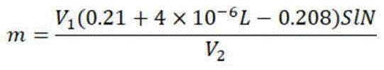
Further, the theoretical number of cryogenic liquid oxygen storage tanks required is m:
wherein L is the planned oxygenation range of the tunnel, S is the section area of the tunnel face, L is the tunneling length of the tunnel, N is the number of the tunnel faces constructed simultaneously, and V 1 Volume of single cryogenic liquid oxygen reserve tank, V 2 Converting liquid oxygen in a single cryogenic liquid oxygen storage tank to a volume of oxygen;
and taking an integer after m/2 as the actual number of the cryogenic liquid oxygen storage tanks in each set of oxygen supply device.
The beneficial effects of the invention are as follows: according to the invention, the ventilation device introduces fresh air outside the tunnel into the oxygen-enriched air bin for collection and storage, and the fresh air is sent to each tunnel face by using the air supply pipeline, so that the cooperative air supply of multiple tunnel faces is completed, and the limit ventilation distance is effectively increased; oxygen supply device supplies oxygen with the oxygen-enriched air storehouse, and new trend mixes with oxygen in the oxygen-enriched air storehouse, forms the oxygen-enriched new trend, and the face of each positive hole is let in to the oxygen-enriched new trend through the air supply pipeline, forms the oxygen-enriched environment near the face, has established a clean oxygen-enriched operational environment, improves long distance tunneling operating personnel's working condition, reduces the harm that low pressure low oxygen brought to the human body, reduces acute and chronic altitude sickness incidence, provides work efficiency, has ensured construction quality.
According to the invention, the storage, distribution and secondary treatment of fresh air flow are completed in the positive tunnel, air is ventilated and supplied to the multiple working surfaces, and the limit ventilation distance is effectively increased on the basis of the traditional ventilation system; and the whole novel ventilation system is flexibly and variably arranged, and each ventilation device is relatively independent and can be used for dynamic device replacement according to the actual conditions in the hole, so that the ventilation energy consumption of construction is greatly reduced, the construction progress is accelerated, and the construction safety is ensured.
The oxygen-enriched air bin is made of flexible materials, so that fresh air leakage in the bin can be effectively avoided, and meanwhile, pollution of polluted air outside the bin to fresh air in the bin can be avoided.
Detailed Description
The invention is further illustrated in the following figures and examples, in which:
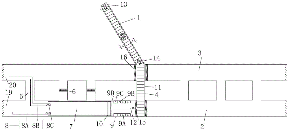
the tunnel air supply system based on oxygen-enriched air storage and oxygenation comprises an inclined shaft 1 and a plurality of positive holes, as shown in fig. 1 or fig. 2, wherein the inclined shaft 1 is directly communicated with the positive holes close to the inclined shaft 1, and the adjacent positive holes are communicated through a plurality of transverse channels arranged at intervals; among the plurality of transverse channels, the transverse channel at the intersection of the centering inclined shaft 1 and the positive tunnel is a connecting channel 4, the transverse channel close to the palm surface is an auxiliary channel 5, and the transverse channel between the connecting channel 4 and the auxiliary channel 5 is blocked by a wind shielding wall 6;
one positive hole is a wind storage tunnel 2, and the rest is a conventional hole 3;
an oxygen-enriched air bin 7 is arranged in the wind storage tunnel 2, one end of the oxygen-enriched air bin 7 facing the tunnel face is an outlet end, and the other end is an inlet end;
the device is provided with a ventilation device for introducing fresh air into the oxygen-enriched air bin 7, and the ventilation device is laid along the inclined shaft 1, passes through the connecting channel 4 and is connected into the oxygen-enriched air bin 7 from the inlet of the oxygen-enriched air bin 7;
an air supply pipeline 8 for supplying fresh air in the oxygen-enriched air bin 7 to the tunnel face of each tunnel is arranged, one end of the air supply pipeline 8 is connected with the oxygen-enriched air bin 7 through an outlet of the oxygen-enriched air bin 7, and the other end extends to the vicinity of the tunnel face of each tunnel;
an oxygen supply device 9 for supplying oxygen is arranged outside the oxygen-enriched air bin 7, and the oxygen supply device 9 is communicated with the oxygen-enriched air bin 7.
The positive hole can be a main tunnel hole or a parallel pilot tunnel.
According to the tunnel air supply system based on oxygen-enriched air storage and oxygenation disclosed by the invention, the ventilation device introduces fresh air outside the tunnel into the oxygen-enriched air storage 7 for collection and storage, and the fresh air is sent to the individual tunnel faces by using the air supply pipeline 8, so that the cooperative air supply of the multiple tunnel faces is completed, and the limit ventilation distance is effectively increased; oxygen supply device 9 supplies oxygen to oxygen-enriched air bin 7, fresh air and oxygen mix in oxygen-enriched air bin 7 to form oxygen-enriched fresh air, and the oxygen-enriched fresh air is led into the face of each positive tunnel through air supply pipeline 8, forms oxygen-enriched environment near the face, has established a clean oxygen-enriched operational environment, improves the operating condition of long distance tunneling operation personnel, reduces the harm of low pressure low oxygen to the human body, reduces acute and chronic altitude sickness incidence, provides work efficiency, has ensured construction quality.
The oxygen-enriched air bin 7 is arranged in a multi-hole parallel excavation positive hole section which is excavated in advance, and in the invention, the oxygen-enriched air bin 7 is arranged in the wind storage tunnel 2.
If only one set of oxygen supply device 9 is arranged for supplying oxygen, the oxygen supply device 9 is very likely to occupy the driving space on the premise of meeting the oxygen supply requirement, and in order to avoid the problem, two sets of oxygen supply devices 9 are arranged on two sides of the positive hole along the transverse direction of the positive hole, and the structure can effectively avoid the oxygen supply device 9 occupying the driving area of the tunnel. Each set of oxygen supply device 9 comprises a low-temperature liquid oxygen storage tank 9A, gasification equipment 9B and an air compressor 9C which are connected in sequence; the air compressor 9C of each set of oxygen supply device 9 is connected with the oxygen-enriched air bin 7 through an oxygen supply pipeline 9D. In order to accelerate the mixing of oxygen and fresh air, an oxygen diffusion device 10 is arranged in the oxygen-enriched air bin 7, as shown in fig. 5 and 6, the oxygen diffusion device 10 comprises an annular oxygen diffusion tube 10A, the oxygen diffusion tube 10A is arranged at the inlet end of the oxygen-enriched air bin 7, and an oxygen supply pipeline 9D passes through the inlet end of the oxygen-enriched air bin 7 and is communicated with the oxygen diffusion tube 10A; along the circumferential direction of the oxygen diffusion pipe 10A, air distribution holes are uniformly distributed on one side of the oxygen diffusion pipe 10A aligned with the outlet end of the oxygen-enriched air bin 7, and an oxygen diffuser 10B is arranged on the air distribution holes.
The low-temperature liquid oxygen storage tank 9A is filled with liquid oxygen, the liquid oxygen is gasified into high-purity oxygen through the gasification equipment 9B, the high-purity oxygen forms high-speed air flow and is conveyed to the oxygen diffusion device 10 in the oxygen-enriched air bin 7 through the oxygen supply pipeline 9D, finally the high-speed air flow is sprayed out by the oxygen diffuser 10B on the oxygen diffusion pipe 10A, the diffusion form is conical, the high-speed air flow is dispersed to the section of the whole air bin, and the high-speed air flow flows in the direction of the outlet end of the oxygen-enriched air bin 7 and is mixed with the stored fresh air in the oxygen-enriched air bin 7, so that oxygen-enriched air is formed. The annular oxygen diffusion tube 10A improves the oxygen diffusion area, the uniform distribution of the air distribution holes is beneficial to the uniform diffusion of oxygen, and the arrangement of the oxygen diffusion tube 10A and the air distribution holes reduces the flow area of oxygen in the tube, thereby playing a certain role in pressurization and being beneficial to improving the oxygen diffusion speed.
In order to make each tunnel face have independent air supply pipeline, in order to improve the air supply of each tunnel face, finish the cooperative air supply of the multiple tunnel faces, preferably, the said air supply pipeline 8 includes the air supply pipe one 8A of the air supply of the tunnel face of the air storage tunnel 2 and air supply pipe two 8B of the air supply of the regular tunnel 3;
one end of the first air supply pipe 8A extending into the outlet end of the oxygen-enriched air bin 7 is connected with an air supply fan 8C, and the other end of the first air supply pipe longitudinally extends to the vicinity of the tunnel face of the air storage tunnel 2 along the air storage tunnel 2;
one end of the second air supply pipe 8B extending into the outlet end of the oxygen-enriched air bin 7 is connected with an air supply fan 8C, and the other end of the second air supply pipe longitudinally extends to the auxiliary channel 5 along the air storage tunnel 2 and extends to the vicinity of the tunnel face of the conventional tunnel 3 through the auxiliary channel 5. Wherein, the air supply fan 8C is an SDF axial flow fan special for the tunnel.
The ventilation pipeline can be directly laid to the oxygen-enriched air bin 7 along the inclined shaft 1 and the connecting channel 4 to convey fresh air to the oxygen-enriched air bin 7, however, the ventilation pipeline is arranged in the inclined shaft 1, the maintenance of the ventilation pipeline is difficult, and the ventilation energy consumption is high. In order to avoid the above problems, as shown in fig. 3, the ventilation device includes a supply air passage 1A and a primary air compartment 11; a baffle plate 1C is arranged in the inclined shaft 1 to divide the inclined shaft 1 into an air supply channel 1A positioned at the upper part and an air exhaust channel 1B positioned at the lower part; the primary air bin 11 is arranged in the connecting channel 4; the primary air bin 11 is communicated with the air supply channel 1A; the air supply channel 1A is connected with the oxygen-enriched air bin 7 through a relay air pipe 12.
In this structure, the partition plate 1C is a hard plate, and the partition plate 1C is surrounded by the partition plate 1C and the part of the inclined shaft 1 located above the partition plate 1C to form a circumferentially closed air supply passage 1A, and the air supply passage 1A penetrates the whole inclined shaft 1 in the longitudinal direction of the inclined shaft 1. The part of the inclined shaft 1 below the partition plate 1C and the partition plate 1C are surrounded to form a circumferentially closed exhaust channel 1B, and the exhaust channel 1B longitudinally penetrates through the whole inclined shaft 1 along the inclined shaft 1. The partition board 1C is arranged at a proper position at the partial arch of the cross section of the inclined shaft, the whole tunnel inclined shaft is divided into two parts of cavities of an air supply channel 1A and an air exhaust channel 1B, the air supply channel 1A is used as a guide channel for fresh air to enter a main tunnel and to be pushed to an oxygen-enriched air bin 7 for storage and treatment, and the air exhaust channel 1B is used as a drain channel for sewage discharge of the main tunnel face; the exhaust channel 1B is used as a sewage drain and is also used as a construction vehicle access channel, the arrangement position of the partition board 1C should fully consider the size of construction equipment and vehicles in the access hole, and a large enough clearance section is reserved to ensure the normal operation of construction procedures and the safety of equipment.
The primary air bin 11 is a closed space, one end of the primary air bin adjacent to the inclined shaft 1 is provided with an opening communicated with the air supply channel 1A, and one side of the primary air bin adjacent to the oxygen-enriched air bin 7 is provided with an opening for installing the relay air pipe 12, so that fresh air is conveyed to the primary air bin 11 for storage through the air supply channel 1A and then conveyed to the oxygen-enriched air bin 7 through the relay air pipe 12. The primary air bin 11 completes the primary air storage function.
The main drainage fans 13 can be arranged at the wellhead of the inclined shaft to send external fresh air into the air supply channel 1A, and the plurality of auxiliary drainage fans 14 are arranged in the air supply channel 1A at equal intervals so as to overcome the along-path resistance caused by the wall surface of the inclined shaft 1 and the air supply channel 1A and accelerate the fresh air conveying speed in the air supply channel 1A. In order to avoid the problem, a main drainage fan 13 and an auxiliary drainage fan 14 are arranged in the air supply channel 1A; the main drainage fan 13 is an SDF multipolar axial flow fan special for tunnels and is positioned at the wellhead of the inclined shaft; the auxiliary drainage fan 14 is a jet fan special for SF tunnels and is positioned at the intersection of the inclined shaft 1 and the positive tunnel. This structure sets up vice drainage fan 14 in the shaft bottom position of inclined shaft 1, can unify and supply power and overhaul all vice drainage fans 14, need not to lay a plurality of power and inspection port along the inclined shaft is vertical.
A relay fan 15 is arranged in the primary air bin 11, one end of a relay air pipe 12 is connected with the relay fan 15, and the other end extends to the oxygen-enriched air bin 7 and is communicated with the inlet end of the oxygen-enriched air bin 7. After fresh air is conveyed into the air supply channel 1A through the main drainage fan 13, the fresh air is pushed by wind pressure of the auxiliary drainage fan 14 to quickly reach the primary air bin 11, the relay fan 15 is opened at the moment, the fresh air is pushed to the oxygen-enriched air bin 7 through the relay air pipe 12, the external gasification equipment 9B and the air compressor 9C are opened at the moment, liquid oxygen in the low-temperature liquid oxygen storage tank 9A is gasified and then enters the air compressor 9C to be pressurized, oxygen is supplied to the oxygen-enriched air bin 7 through the oxygen supply pipeline 9D in a high-speed high-pressure state through the oxygen diffuser 10B, artificial active oxygen increasing is carried out, high-purity oxygen is dispersed in the oxygen-enriched air bin 7 and is effectively mixed with fresh air conveyed into the oxygen-enriched air bin 7 through the relay air pipe 12 in the middle of the flowing in the oxygen-enriched air bin 7, so that oxygen-enriched air of the whole oxygen-enriched air bin 7 is formed, when the oxygen-enriched air bin 7 is full of sufficient oxygen-enriched air is timely replaced according to actual use, the low-temperature liquid oxygen storage tank 9A is opened, the air supply fan 8C is respectively conveyed to the vicinity of the palm face through the oxygen-enriched air through the pipeline 8, fresh air is replaced through the oxygen-enriched air hole, and the polluted air is discharged to the outside the whole ventilation channel 1 through the inclined shaft 1B.
An independent columnar wind bin can be arranged as a primary wind bin 11, and optimally, the partition plate 1C sequentially passes through the positive hole close to the inclined shaft 1 and the transverse channel along the transverse direction of the tunnel to extend into the conventional hole 3 far from the inclined shaft 1; along the longitudinal direction of the tunnel, the air surfaces between the two ends of the partition board 1C and the corresponding positive tunnel vault are sealed by the air-blocking curtains 16, and the primary air bin 11 is formed by enclosing the partition board 1C, the parts of the positive tunnels and the transverse channels above the partition board 1C and the air-blocking curtains 16;
the part below the partition board 1C is communicated with the positive hole to form a sewage duct.
This structure adopts baffle 1C, windward curtain 16 and current positive hole and links up passageway 4 and surrounds and form primary air storehouse 11, has rationally utilized the current structure of tunnel, and its construction cost and engineering time all obtain the reduction.
The air quantity can be stored in a traditional mode by taking a closed section formed by the hard partition plate and the positive hole wall surface as the oxygen-enriched air bin 7. However, because the oxygen-enriched air bin 7 is arranged in the positive hole, the cross section of the positive hole is large, when the radial length of the cross section is too long, the hard partition plate is too heavy, and in the middle suspended state, a large amount of air leakage in the bin is easily caused by local damage, and the tunnel task in the construction section is frequent, the middle partition plate is required to be disassembled when the hard air bin section is arranged for construction, so that the air supply of the tunnel face is seriously hindered, and the construction progress is delayed; in order to avoid the problems, the oxygen-enriched air bin 7 is made of high-strength flexible materials such as PVC, plastic coated chemical fiber fabrics and the like, is integrally in a cylindrical bin, has a semicircular transverse section and is attached to the top of the wind storage tunnel 2 arch. The oxygen-enriched air bin 7 made of flexible materials has certain deformability under the action of wind force, can effectively solve the problem of air leakage, is simple in structure, light and convenient, is flexible to arrange, and can be effectively applied to the long-distance tunnel construction process.
As shown in fig. 4, the top wall of the oxygen-enriched wind bin 7 is semi-circular, and comprises a top wall 7A with an arc shape and a horizontal bottom wall 7B; a plurality of hanging hooks 7E are arranged on the top wall 7A along the annular direction of the top wall 7A, and the hanging hooks 7E are hung on the vault of the wind storage tunnel 2; the air conditioner is provided with a suspension rod 7F, and two ends of the suspension rod 7F are respectively fixed on the side walls of two sides of the air storage tunnel 2; the bottom wall 7B of the oxygen-enriched air bin 7 is located on the suspension rod 7F, so that the oxygen-enriched air bin 7 is firmly installed on the vault part of the air storage tunnel 2, and the space of the air storage tunnel 2, which is located at the lower part of the oxygen-enriched air bin 7, meets the running requirement of a vehicle. The outlet end and the inlet end of the oxygen-enriched air bin 7 are both closed by an end wall 7C, and a preformed hole is formed in the end wall 7C positioned at the inlet end and used for being connected with the relay air pipe 12 and the oxygen supply pipeline 9D; the end wall 7C at the outlet end is provided with a preformed hole for docking the air supply fan 8C.
The oxygen-enriched wind bin 7 limits the cross-sectional area of the wind bin by using a mode of fixing flexible cloth by using a hanging and supporting device, accelerates wind flow transmission, leaves enough cross-sectional clearance, and completes efficient wind storage and secondary transportation on the premise of not affecting the normal operation of the construction vehicle in the hole.
In order to ensure the air quantity of the tunnel face, save the space in the tunnel to a great extent, and arrange reasonably and accelerate the construction progress, preferably, along the longitudinal direction of the tunnel, as shown in fig. 7, the oxygen-enriched air bin 7 is in a ladder shape formed by butting a plurality of sections of air bin sections 7D, and the number and arrangement sequence of the air bin sections 7D are not limited to the form shown in fig. 7. The length of the segment of single Duan Fengcang is 90-110m. The interface adopts the soft joint of fire prevention zinc-plated PVC, carries out the sealing strip and handles, and whole length is decided jointly by positive tunnel tunneling length, each tuber pipe length, according to actual engineering ventilation volume demand, carries out the strict control to oxygen boosting wind storehouse 7 length, when satisfying face amount of wind demand, effectively prolongs the limit length that the construction ventilated.
The oxygen-enriched air bin 7 is arranged in the wind storage tunnel 2, the length of the oxygen-enriched air bin is set according to the excavation length L of the arrangement section, the construction procedures near the face are more, the construction range is X meters, the oxygen-enriched air bin 7 is arranged from a proper position away from the connecting channel 4, the length of the oxygen-enriched air bin 7 is simplified to L-X until the position of the construction section is X meters, and in order to ensure that the oxygen-enriched air bin 7 can simultaneously supply enough fresh air for a plurality of tunnel faces, the tunnel faces are taken to be in a hole after ventilation blastingCalculating the maximum condition of the required air volume, taking the maximum value of the required air volume in each tunnel face as a standard, and setting the required air volume as Q x The number of the tunnel faces is N, and the total air storage amount of the oxygen-enriched air bin 7 is as follows when the single circulation process time T is: w=ntq x The area of the initial section of the oxygen-enriched air bin 7 is A, the initial section of the oxygen-enriched air bin 7 is calculated according to a semicircle, the height of a single step is h, the length is a, and the number of steps is n.
In order to simplify the calculation, assuming that the stepped oxygen-enriched air bin 7 is formed by combining an initial semi-cylindrical body with an additional hexahedral body, and the volume increment thereof is calculated according to the volume of the hexahedral body, the air reserve amount in the oxygen-enriched air bin 7 is as follows:
let w=ntq x Substituting the above formula, then:
the simplification can be obtained:
K 1 n 2 +K 2 n=K 3 a -1
wherein :
assuming equal step lengths, then: l-x=na, substituting the above to calculate the number of steps of the oxygen-enriched wind bin 7 as n:
wherein: n is the number of steps of the oxygen-enriched wind bin; n is the number of the construction face surfaces at the same time; q (Q) x The maximum required air quantity of the tunnel face is obtained; l is tunneling length; x is the construction range of the face; h is the height of a single step; a is the cross-sectional area of the initial wind bin.
Because constructor and mechanical equipment consume oxygen in the positive hole, along with the increase of positive hole footage, the oxygen content in the hole can reduce gradually, and the oxygen deficiency can lead to constructor's uncomfortable, syncope even death, consequently the needs oxygen suppliment to positive hole job site to guarantee constructor's safety.
The oxygen content in plain atmosphere is about 20.947%, taken according to 21%, after the tunneling length exceeds 2000m according to field experience, the oxygen content starts to be in a descending trend, at 2000m, the oxygen content is about 0.2, at 3000m, the oxygen content is 0.196, the oxygen content is set to be in a linear decrease along with the increase of the tunnel length, and the relation between the corresponding tunneling depth L and the oxygen content is:
O=-4×10 -6 L+0.208
wherein: o is oxygen content, and L is tunneling depth.
The oxygen concentration ratio to be increased is 0.21-O, oxygenation is supposed to be carried out in the range of throwing the gun smoke, the maximum face needing oxygenation is taken as a standard, N face faces are taken as a total, namely the total quantity needing oxygenation is as follows:
M o =(0.21+4×l0 -6 L-0.208)NSl
wherein :Mo To increase oxygen, the unit is m 3 The method comprises the steps of carrying out a first treatment on the surface of the L is tunneling depth, and the unit is m; n is the number of the construction face surfaces at the same time; s is the cross-sectional area of the face, and the unit is m 2 The method comprises the steps of carrying out a first treatment on the surface of the l is the planned oxygenation range of the tunnel, and the unit is m.
Preferably, in the embodiment, the volume of the single small liquid oxygen tank is V 1 Liquefying to obtain high-concentration oxygen with volume of V 2 The total required number is:
in the embodiment shown in figure 1 of the drawings,
the tunnel comprises an inclined shaft 1, a parallel pilot tunnel communicated with the inclined shaft 1 and a right positive tunnel communicated with the parallel pilot tunnel through a transverse channel. The right positive hole is a wind storage tunnel 2, and the parallel pilot hole is a conventional hole 3. Tunnel construction length in this embodimentL is 5000m, the right main tunnel face and the parallel pilot tunnel face are excavated simultaneously, the construction air quantity is calculated according to related industry specifications, and Q is taken x =3000m 3 And/min, the construction range X near the tunnel face is 500m, and the section of the right positive tunnel is 120m 2 According to the size of the right positive hole section, the initial wind bin section area A is 30m 2 Taking 1m for a single step height h, and taking 30min for blasting ventilation time, and then:
the number of steps of the oxygen-enriched air bin is 2, the total length of the oxygen-enriched air bin is 4500m, the single step length is 2250m, the step height is 1m, the oxygen-enriched air bin is arranged by taking the step length as a reference, and the oxygen-enriched air bin is correspondingly adjusted according to actual engineering conditions.
A single small liquid oxygen tank with the volume of 1m is selected 3 Liquefying into high-concentration oxygen with volume of 800m 3 The total required number of the single small liquid oxygen tanks is:
according to the calculation result, 1 low-temperature liquid oxygen refrigerating tanks are respectively arranged at the left side and the right side of the tail end of the oxygen-enriched air bin 7. According to 6m 3 Flow rate/h, 8 hours per day, 1m 3 The liquid oxygen in the tank can be used for about 16 days, and in order to ensure that the low-temperature liquid oxygen tank in the hole is kept enough and surplus at all times, the replacement of a single liquid oxygen tank is preliminarily planned every 16 days.
The embodiment shown in fig. 2 is that a long tunnel is constructed on a multi-tunnel face at the same time, and the tunnel comprises a left positive hole communicated with the inclined shaft 1 by an inclined shaft 1, a parallel pilot hole directly communicated with the left positive hole by a transverse channel, and a right positive hole directly communicated with the parallel pilot hole by the transverse channel, wherein in the embodiment, the parallel pilot hole is a wind storage tunnel 2, and the right positive hole and the left positive hole are regular holes 3.
In the embodiment, the tunnel construction length L is 5000m, the face of the main tunnel and the face of the parallel pilot tunnel are excavated simultaneously, and the tunnel is constructed according to the related industry standardCalculating the air quantity required by construction, and taking Q x =3000m 3 And/min, the construction range X near the tunnel face is 500m, and the section of the positive tunnel is 120m 2 According to the tunnel section size, the initial wind bin section area A is 30m 2 Taking 1m for a single step height h, taking 30min for blasting ventilation time, 5 tunnel faces in the tunnel, and simultaneously taking the maximum number of constructed tunnel faces into consideration of n=3, wherein the maximum number is calculated according to the formula:
the number of steps of the oxygen-enriched air bin 7 is 5, the total length of the air bin is 4500m, the single step length is 900m, the step height is 1m, the oxygen-enriched air bin 7 is arranged by taking the single step length as a reference, and the steps are correspondingly adjusted according to actual engineering conditions.
In the embodiment, the tunnel construction length L is 5000m, the blasting smoke throwing range, namely the tunnel oxygenation range L is 100m, and the section of the positive tunnel is 120m 2 And (3) simultaneously constructing the tunnel face, wherein n is 5, and substituting the above formula to the tunnel face, so that:
according to the calculation result, 1 low-temperature liquid oxygen refrigerating tanks are respectively arranged at the left side and the right side of the tail end of the secondary air bin. According to 6m 3 Flow rate/h, 8 hours per day, 1m 3 The liquid oxygen in the tank can be used for about 16 days, and in order to ensure that the low-temperature liquid oxygen tank in the hole is kept enough and surplus at all times, the replacement of a single liquid oxygen tank is preliminarily planned every 16 days.