CN113445816A - Recyclable enclosure with expanded end and construction method thereof - Google Patents
Recyclable enclosure with expanded end and construction method thereof Download PDFInfo
- Publication number
- CN113445816A CN113445816A CN202110792604.4A CN202110792604A CN113445816A CN 113445816 A CN113445816 A CN 113445816A CN 202110792604 A CN202110792604 A CN 202110792604A CN 113445816 A CN113445816 A CN 113445816A
- Authority
- CN
- China
- Prior art keywords
- upright post
- enclosure
- fence
- round steel
- circulating
- Prior art date
- Legal status (The legal status is an assumption and is not a legal conclusion. Google has not performed a legal analysis and makes no representation as to the accuracy of the status listed.)
- Pending
Links
Images


Classifications
-
- E—FIXED CONSTRUCTIONS
- E04—BUILDING
- E04H—BUILDINGS OR LIKE STRUCTURES FOR PARTICULAR PURPOSES; SWIMMING OR SPLASH BATHS OR POOLS; MASTS; FENCING; TENTS OR CANOPIES, IN GENERAL
- E04H17/00—Fencing, e.g. fences, enclosures, corrals
- E04H17/14—Fences constructed of rigid elements, e.g. with additional wire fillings or with posts
- E04H17/16—Fences constructed of rigid elements, e.g. with additional wire fillings or with posts using prefabricated panel-like elements, e.g. wired frames
- E04H17/17—Fences constructed of rigid elements, e.g. with additional wire fillings or with posts using prefabricated panel-like elements, e.g. wired frames brackets for the connection between panels and posts
-
- E—FIXED CONSTRUCTIONS
- E04—BUILDING
- E04H—BUILDINGS OR LIKE STRUCTURES FOR PARTICULAR PURPOSES; SWIMMING OR SPLASH BATHS OR POOLS; MASTS; FENCING; TENTS OR CANOPIES, IN GENERAL
- E04H17/00—Fencing, e.g. fences, enclosures, corrals
- E04H17/14—Fences constructed of rigid elements, e.g. with additional wire fillings or with posts
- E04H17/20—Posts therefor
- E04H17/22—Anchoring means therefor, e.g. specially-shaped parts entering the ground; Struts or the like
Landscapes
- Engineering & Computer Science (AREA)
- Architecture (AREA)
- Civil Engineering (AREA)
- Structural Engineering (AREA)
- Fencing (AREA)
Abstract
A recyclable enclosure with an expanded end and a construction method thereof belong to the technical field of buildings. The foundation is formed by combining a round steel pipe which is inserted underground and the end part of which can be freely expanded and a backing plate of which the top is prevented from sinking; the upright posts and the foundation are arranged at the same vertical position up and down and are connected by a pipe at the dome shape to form a fence frame; the horizontal square pipe is arranged between the stand columns, the horizontal square pipe is connected with the stand columns through two different types of clamps, a galvanized iron plate is arranged on the horizontal square pipe to form a surrounding plane, and the horizontal square pipe and the galvanized iron plate are connected into a whole through a first connecting piece and a second connecting piece. The invention adopts factory prefabrication, ensures the quality, is convenient to install, does not need to carry out on-site welding, has high construction speed, needs less auxiliary materials and human resources during construction, is convenient to organize and construct, is convenient to disassemble, transport and store, is not easy to damage in the transport process and has good economic benefit.
Description
Technical Field
The invention belongs to the technical field of buildings, and particularly relates to a circulating enclosure with an expanded end and a construction method thereof.
Background
The engineering enclosure is a temporary wall body which needs to be built before the construction of a building structure. In the building construction process, the engineering enclosure has the function of isolating the construction site from the external environment, so that the construction site becomes an independent space, and the safety of the construction site and the external environment is ensured.
The existing widely used engineering enclosure forms comprise a concrete pouring type, a masonry material masonry type, a prefabricated assembly type and a section steel assembly welding type.
For the enclosure of concrete pouring and masonry material building, the enclosure which is just cast on site is complex to manufacture during construction, the construction procedures of concrete are more, the construction period is longer, the enclosure can not be recycled, the cost is higher for a long time, and a large amount of building waste can be generated to pollute the environment when the enclosure is dismantled; meanwhile, a large amount of manpower and material resources are required to be mobilized during construction, and the management difficulty and the resource scheduling difficulty are high; maintenance is needed after construction is completed, and potential safety hazards exist. For the prefabricated assembled enclosure, although the defects of cast-in-place concrete are avoided, the weight of a prefabricated concrete component is large, a large amount of human resources are used in the construction process, hoisting equipment is used for hoisting, the construction process and organization management are complex, and meanwhile, the prefabricated concrete component is generally heavy, so that the prefabricated assembled enclosure is also a great problem in the construction turnover process. For the enclosure for assembling and welding the profile steel, although various defects in the concrete construction process are avoided, the amount of steel is increased, the space occupied by the structure is relatively increased, welding work is required in the assembling process, and cutting and dismantling operation is required after the building construction is finished, so that time and labor are consumed, and more potential safety hazards exist.
The circulating enclosure with the expanded end and the construction method thereof well solve various problems of the enclosure. The invention has the following effects and advantages:
1) the method for breaking up the whole into parts is adopted, the enclosure is disassembled into different types of unit components, each unit component is connected into a whole by using the bolts and the clamps, the field welding is avoided, the safe and civilized construction is realized, and the construction progress is accelerated;
2) the connecting piece has delicate design, stable connection and light material, and the adopted round steel, section steel and angle steel are all common steel, so that the connecting piece is convenient to process and supply;
3) each unit component is prefabricated in a factory, so that the device is convenient to install, convenient to control quality, free of additional auxiliary materials during construction, less in human resource requirement, convenient to organize and construct, convenient to disassemble, transport and store, not prone to damage in the transport process, high in recycling degree and good in economic benefit.
Disclosure of Invention
In order to solve the technical problems, the invention provides a circulating enclosure with an expanded end part and a construction method thereof.
The technical scheme adopted by the invention is as follows:
the invention relates to a circulating enclosure with an expanded end part, which comprises an upright post, an upright post foundation, an anti-settling base plate, a hemispherical dome pipe, a clamp, a transverse square pipe and an enclosure panel, wherein the upright post foundation is provided with a plurality of upright posts; the upright posts and the upright post foundations are arranged up and down at the same positions and are connected into a whole at the ground by virtue of the hemispherical square tubes; the upper half part of the upright post foundation is a round steel pipe, and the lower half part of the upright post foundation is provided with an expansion device; the anti-settling liner plate is sleeved on the round steel pipe on the upper half part of the stand column foundation, and an anti-settling steel column is inserted into a bolt hole in the round steel pipe to fix the anti-settling liner plate, so that the settlement and the inclination after the construction process and the enclosure completion are prevented; after the anti-settling base plate is installed, the end part of the expansion device is expanded by screwing the nut at the top of the vertical long steel column in the round steel pipe, and the upright column foundation is fixed in the ground to play a role; the clamp is fixed on the upright post through a long bolt and is used for connecting and fixing the transverse square tube to form a basic frame of the enclosure; the enclosure panel is fixed on the transverse square pipe by a first connecting piece and a second connecting piece to form a basic plane of the enclosure, and the basic plane is hung on the clamp to form an integral structure of the enclosure.
Further, the upright post is a square column, bolt holes are formed in the upper portion and the middle lower portion of the upright post, and the clamp is fixed on the upright post through long bolts.
Further, the top and the bottom of the round steel tube of the first half of stand basis all are equipped with the round steel piece of trompil, and the round steel tube has seted up the bolt hole apart from top 150mm distance department.
Furthermore, the top of the expansion device is fixed at the bottom of the circular steel tube, the bottom of the expansion device is fixed together, the top and the bottom of the expansion device are connected through two steel columns with equal length, and the bottom of the expansion device is connected with a vertical long steel column with threads at the top end.
Furthermore, the outer side length of the upright post is the same as the outer diameter of the round steel tube at the upper half part of the upright post base, and the outer diameter of the round steel tube is 48.3 mm.
Furthermore, the anti-settling base plate is a wooden square base plate, and a round hole with the same diameter as the round steel pipe is formed in the middle of the anti-settling base plate.
Furthermore, the side length of the square pipe of the square.
Furthermore, the length of the inner side of the square tube, the inner diameter of the round steel tube, the length of the outer side of the upright post and the outer diameter of the upright post base are the same and are all 48.3 mm.
Further, the material of anchor clamps is the angle steel, acts on respectively on enclosing the both ends of keeping off and the stand in the middle of keeping off to anchor clamps all use in pairs.
Furthermore, the surrounding baffle panel is a galvanized thin iron plate, and an upper row and a lower row of round holes are formed at intervals of 200 mm.
The invention has the beneficial effects that:
1) the effect and the advantage of the invention are that the circular enclosure with the expanded end part adopts the method of breaking up the whole into parts, the enclosure is disassembled into different types of unit components, each unit component is connected into a whole by using bolts and clamps, the on-site welding is avoided, the safe and civilized construction is realized, and the construction progress is accelerated;
2) the connecting piece has delicate design, stable connection and light material, and the adopted round steel, section steel and angle steel are all common steel, so that the connecting piece is convenient to process and supply;
3) the utility model provides an every unit component that circulated formula that tip was expanded and is enclosed fender all adopts mill's prefabrication, simple to operate, and the quality is convenient for control, need not extra auxiliary material during the construction, manpower resources are required less, organizes construction convenience, dismantlement, transportation and save the convenience, should not damage in the transportation, circulated degree is high, and economic benefits is good.
Drawings
FIG. 1 is a general schematic view of a circular enclosure with an enlarged end and a construction method thereof according to the present invention;
FIG. 2 is a three-dimensional schematic view of a clamp (2) in the circular enclosure with an expanded end and the construction method thereof;
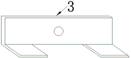
FIG. 3 is a three-dimensional schematic view of a clamp (3) in the circular enclosure with an expanded end and the construction method thereof;
FIG. 4 is a schematic view of a circulating fence with an enlarged end and a long bolt (11) in the construction method of the circulating fence;
FIG. 5 is a schematic view showing the effect of the clamps (2) and (3) fixed to the vertical column (1) in the circular enclosure with the expanded ends and the construction method thereof according to the present invention;
FIG. 6 is a front view of a circular earth square pipe (7) in the circular enclosure with an enlarged end and the construction method thereof of the present invention;
FIG. 7 is a plan view of a circular earth square pipe (7) in the circular enclosure with an enlarged end and the construction method thereof according to the present invention;
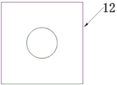
FIG. 8 is a schematic view showing the effect of installing the anti-settling shim plate (12) on the upright post (1) in the circular retaining fence with the expanded end and the construction method thereof according to the present invention;
FIG. 9 is a schematic view of a foundation (6) of a circular fence with an enlarged end and a construction method thereof according to the present invention;
FIG. 10 is a top schematic view of an expanding device (17) in the circulating fence with an expanded end and the construction method thereof according to the present invention;
FIG. 11 is a schematic bottom view of an expanding device (17) in the circulating fence with an expanded end and the construction method thereof according to the present invention;
FIG. 12 is a schematic view of a steel column connection node of an end-expanded circulating fence and an expansion device (17) in the construction method thereof;
FIG. 13 is a schematic view of a circular retaining wall with an enlarged end and an anti-settling shim plate (12) in the construction method of the circular retaining wall;
FIG. 14 is a schematic view of a second connecting member (5) in the circulating fence with an expanded end and the construction method thereof.
In the figure, 1-column; 2-clamping; 3, clamping; 4-a first connector; 5-a second connector; 6-column foundation; 7-round-sky and square-earth tube; 8-the top of the expansion device; 9-steel column connecting nodes of the expansion device; 10-the bottom of the expansion device; 11-long bolt; 12-anti-settling pad plates; 13-anti-settling steel columns; 14-transverse square tubes; 15-fencing panel; 16-round steel pipe; 17-an expansion device; 18-bolt holes; 19-round holes; 20-vertical long steel columns; 21-bolt hole.
Detailed Description
Example (b): as shown in fig. 1-9, the present invention comprises a column 1, a column foundation 6, an anti-settling pad 12, a square tube 7, clamps 2 and 3, a transverse square tube 14, and a surrounding baffle plate 15; the upright post 1 and the upright post foundation 6 are arranged up and down at the same position and are connected into a whole at the ground by a hemispherical tube 7; as shown in fig. 9, the upper half part of the upright post foundation 6 is a round steel pipe 16, and the lower half part is provided with an expansion device 17; as shown in fig. 8, the anti-settling shim plate 12 is sleeved on a round steel pipe 16 of the upper half part of the column foundation 6, and an anti-settling steel column 13 is inserted into a bolt hole 18 of the round steel pipe 16 to fix the anti-settling shim plate 12, so that the anti-settling shim plate can prevent settling and inclination in the construction process and after the enclosure is completed; the expansion device 17 is used for expanding the end part of the expansion device by screwing the nut at the top of the vertical long steel column 20 in the circular steel tube 16 after the anti-settling base plate 12 is installed, and fixing the upright column base in the ground to play a role; as shown in fig. 5, the clamp 3 is fixed on the upright 1 through a long bolt 11 and is used for connecting and fixing a transverse square pipe 14 to form a basic frame of the enclosure; as shown in FIG. 1, the enclosure panel 15 is fixed on the transverse square tube 14 by the first connecting piece 4 and the second connecting piece 5 to form a basic plane of the enclosure, and the basic plane is hung on the clamp 3 to form an integral structure of the enclosure.
As shown in fig. 5, the upright 1 is a square column, wherein bolt holes 21 are formed in the upper portion and the middle-lower portion, and the clamps 2 and 3 are fixed on the upright 1 by long bolts 11.
As shown in fig. 9, the top and the bottom of the circular steel tube 16 of the upper half portion of the column base 6 are both provided with perforated circular steel sheets, and the circular steel tube 16 is provided with bolt holes 18 at a distance of 150mm from the top.
As shown in fig. 9, the top of the expansion device 17 is fixed to the bottom of the circular steel tube 16, the bottom is fixed together, the top and the bottom are connected through two steel columns with equal length, and the bottom is connected with a vertical long steel column 20 with threads at the top end.
As shown in fig. 8, the outer side length of the column 1 is the same as the outer diameter of the round steel tube 16 of the upper half of the column base 6, and both are 48.3 mm.
As shown in fig. 13, the anti-settling mat 12 is a wooden square mat, and a circular hole with the same diameter as the round steel tube 16 is formed in the middle.
As shown in fig. 6 and 7, the square pipe of the square pipe 7 has the same side length and the same diameter as the circular pipe, both the side length and the diameter are 48.3mm, and both ends of the transition part are provided with a square steel sheet and a circular steel sheet with holes.
As shown in fig. 1, the inner side length of the square tube of the pipe 7, the inner diameter of the round steel tube, the outer side length of the column 1 and the outer diameter of the column base 6 are all the same, and are all 48.3 mm.
As shown in fig. 2 and 3, the clamps 2 and 3 are made of angle steel, and respectively act on the two ends of the enclosure and the middle upright post 1, and the clamps 2 and 3 are used in pairs.
As shown in fig. 1, the surrounding baffle plate 15 is a galvanized thin iron plate, and two rows of circular holes 19 are formed at intervals of 200 mm.
Claims (10)
1. The utility model provides a circulated formula that tip is expanded encloses fender which characterized in that: the anti-settling device comprises a stand column (1), a stand column foundation (6), an anti-settling base plate (12), a hemispherical tube (7), clamps (2) and (3), a transverse square tube (14) and a surrounding baffle panel (15); the upright post (1) and the upright post foundation (6) are arranged up and down at the same position and are connected into a whole at the ground by a pipe (7) at the dome; the upper half part of the column foundation (6) is a round steel pipe (16), and the lower half part is provided with an expansion device (17); the anti-settling base plate (12) is sleeved on a round steel pipe (16) on the upper half part of the column foundation (6), and an anti-settling steel column (13) is inserted into a bolt hole (18) in the round steel pipe (16) to fix the anti-settling base plate (12) so as to prevent settling and inclination in the construction process and after the enclosure is completed; after the anti-settling base plate (12) is installed, the end part of the expansion device (17) is expanded by screwing the nut at the top of the vertical long steel column (20) in the circular steel tube (16) so as to fix the upright column foundation in the ground to play a role; the clamp (3) is fixed on the upright post (1) through a long bolt (11) and is used for connecting and fixing a transverse square pipe (14) to form a basic frame of the enclosure; the enclosure panel (15) is fixed on the transverse square pipe (14) by a first connecting piece (4) and a second connecting piece (5) to form a basic plane of the enclosure, and the basic plane is hung on the clamp (3) to form an integral structure of the enclosure.
2. A circulating fence with an enlarged end as claimed in claim 1 wherein: the upright post (1) is a square column, wherein bolt holes (21) are formed in the upper portion and the middle lower portion of the upright post, and the clamps (2) and (3) are fixed on the upright post (1) through long bolts (11).
3. A circulating fence with an enlarged end as claimed in claim 1 wherein: the top and the bottom of the round steel tube (16) of the upper half part of the column foundation (6) are both provided with round steel sheets with holes, and the round steel tube (16) is provided with bolt holes (18) at a distance of 150mm from the top.
4. A circulating fence with an enlarged end as claimed in claim 1 wherein: the top of the expansion device (17) is fixed at the bottom of the round steel pipe (16), the bottoms of the expansion device are fixed together, the top and the bottom are connected through two steel columns with equal length, and the bottom is connected with a vertical long steel column (20) with threads at the top end.
5. A circulating fence with an enlarged end as claimed in claim 1 wherein: the outer side length of the upright post (1) is the same as the outer diameter of the round steel tube (16) at the upper half part of the upright post base (6), and the outer side length and the outer diameter are both 48.3 mm.
6. A circulating fence with an enlarged end as claimed in claim 1 wherein: the anti-settling base plate (12) is a wooden square base plate, and a round hole with the same diameter as the round steel pipe (16) is formed in the middle of the anti-settling base plate.
7. A circulating fence with an enlarged end as claimed in claim 1 wherein: the side length of a square tube of the square tube (7) is the same as the diameter of a round tube, the side length of the square tube is 48.3mm, and both ends of a transition part of the square tube are provided with a square steel sheet and a round steel sheet with holes.
8. A circulating fence with an enlarged end as claimed in claim 1 wherein: the inner side length of the square tube (7), the inner diameter of the round steel tube, the outer side length of the upright post (1) and the outer diameter of the upright post foundation (6) are all the same and are 48.3 mm.
9. A circulating fence with an enlarged end as claimed in claim 1 wherein: the material of anchor clamps (2) (3) is the angle steel, acts on respectively on enclosing the both ends of keeping off and middle stand (1) to anchor clamps (2) and anchor clamps (3) all use in pairs.
10. A circulating fence with an enlarged end as claimed in claim 1 wherein: the enclosure panel (15) is a galvanized thin iron plate, and is provided with an upper row of round holes and a lower row of round holes (19) at intervals of 200 mm.
Priority Applications (1)
| Application Number | Priority Date | Filing Date | Title |
|---|---|---|---|
| CN202110792604.4A CN113445816A (en) | 2021-07-14 | 2021-07-14 | Recyclable enclosure with expanded end and construction method thereof |
Applications Claiming Priority (1)
| Application Number | Priority Date | Filing Date | Title |
|---|---|---|---|
| CN202110792604.4A CN113445816A (en) | 2021-07-14 | 2021-07-14 | Recyclable enclosure with expanded end and construction method thereof |
Publications (1)
| Publication Number | Publication Date |
|---|---|
| CN113445816A true CN113445816A (en) | 2021-09-28 |
Family
ID=77816028
Family Applications (1)
| Application Number | Title | Priority Date | Filing Date |
|---|---|---|---|
| CN202110792604.4A Pending CN113445816A (en) | 2021-07-14 | 2021-07-14 | Recyclable enclosure with expanded end and construction method thereof |
Country Status (1)
| Country | Link |
|---|---|
| CN (1) | CN113445816A (en) |
Citations (9)
| Publication number | Priority date | Publication date | Assignee | Title |
|---|---|---|---|---|
| CN104314362A (en) * | 2014-10-24 | 2015-01-28 | 张玉恒 | All-prefabricated fence |
| CN105696851A (en) * | 2016-04-25 | 2016-06-22 | 北京城建七建设工程有限公司 | Totally-prefabricated assembly type construction barrier and construction method thereof |
| CN205677361U (en) * | 2016-04-25 | 2016-11-09 | 北京城建七建设工程有限公司 | Full prefabricated assembling construction guard fender |
| CN206737563U (en) * | 2017-03-13 | 2017-12-12 | 淮南虎龙钢结构有限公司 | A kind of construction guard fender quickly assembled |
| CN208533466U (en) * | 2018-06-22 | 2019-02-22 | 衡水胜特科技有限公司 | Anti- ship hits facility through hole skirt structure |
| CN109797869A (en) * | 2019-02-01 | 2019-05-24 | 天津大学 | A kind of construction method of rectangular steel-tube concrete column splicing node |
| CN209760969U (en) * | 2019-01-22 | 2019-12-10 | 中国一冶集团有限公司 | Construction enclosure with assembled foundation |
| CN210460179U (en) * | 2019-05-10 | 2020-05-05 | 上海二十冶建设有限公司 | Combined construction enclosure |
| CN111577001A (en) * | 2020-06-09 | 2020-08-25 | 广西宏丰建筑工程有限公司 | Temporary enclosure fixing piece for non-hardened area and construction method thereof |
-
2021
- 2021-07-14 CN CN202110792604.4A patent/CN113445816A/en active Pending
Patent Citations (9)
| Publication number | Priority date | Publication date | Assignee | Title |
|---|---|---|---|---|
| CN104314362A (en) * | 2014-10-24 | 2015-01-28 | 张玉恒 | All-prefabricated fence |
| CN105696851A (en) * | 2016-04-25 | 2016-06-22 | 北京城建七建设工程有限公司 | Totally-prefabricated assembly type construction barrier and construction method thereof |
| CN205677361U (en) * | 2016-04-25 | 2016-11-09 | 北京城建七建设工程有限公司 | Full prefabricated assembling construction guard fender |
| CN206737563U (en) * | 2017-03-13 | 2017-12-12 | 淮南虎龙钢结构有限公司 | A kind of construction guard fender quickly assembled |
| CN208533466U (en) * | 2018-06-22 | 2019-02-22 | 衡水胜特科技有限公司 | Anti- ship hits facility through hole skirt structure |
| CN209760969U (en) * | 2019-01-22 | 2019-12-10 | 中国一冶集团有限公司 | Construction enclosure with assembled foundation |
| CN109797869A (en) * | 2019-02-01 | 2019-05-24 | 天津大学 | A kind of construction method of rectangular steel-tube concrete column splicing node |
| CN210460179U (en) * | 2019-05-10 | 2020-05-05 | 上海二十冶建设有限公司 | Combined construction enclosure |
| CN111577001A (en) * | 2020-06-09 | 2020-08-25 | 广西宏丰建筑工程有限公司 | Temporary enclosure fixing piece for non-hardened area and construction method thereof |
Similar Documents
| Publication | Publication Date | Title |
|---|---|---|
| CN210603852U (en) | Full-assembly type steel structure reaction frame | |
| CN212716623U (en) | Corrugated plate well cementation foundation structure and subway vertical shaft | |
| CN109654968B (en) | Protective safety shed for mine blasting | |
| CN110878555A (en) | Large-span underground space deep foundation pit supporting system and construction method | |
| CN213572924U (en) | Novel overhanging bearing scaffold | |
| CN108204039A (en) | A kind of assembled architecture truss structure | |
| CN113445816A (en) | Recyclable enclosure with expanded end and construction method thereof | |
| CN207905104U (en) | A kind of assembled architecture truss structure | |
| CN202152442U (en) | Assembling type steel tube-vertical post system | |
| CN215442339U (en) | Newly-increased steel structure balcony of existing masonry structure house | |
| CN212077954U (en) | Portable assembled deep basal pit steel sheet case supporting construction that can have enough to meet need | |
| CN213572896U (en) | Pole setting device of pole-holding type formwork support | |
| CN212129154U (en) | Prefabricated assembled steel and concrete combined support's underground structure | |
| CN204000936U (en) | Outer wall of basement single surface formwork system based on fastener type steel pipe earth anchor truss | |
| CN111441364A (en) | Recoverable PC worker method combination steel-pipe pile adds steel pipe shaped steel support system | |
| CN219604160U (en) | Trestle bridge plate template support structure for foundation pit supporting limited space | |
| CN219710912U (en) | Land-saving type construction temporary construction platform | |
| CN214783985U (en) | A excavation supporting for among municipal works foundation ditch | |
| CN210003017U (en) | But adopt prefabricated construction of concrete prefabricated section to enclose fender | |
| CN111206592B (en) | Construction method of prefabricated steel-concrete combined support foundation pit supporting structure | |
| CN211286782U (en) | Aluminum template supporting system | |
| CN217500293U (en) | Prefabricated square pile and photovoltaic support | |
| CN216007965U (en) | Reinforcing bar processing canopy | |
| CN213233522U (en) | Column base connecting device of steel column applied to underground mechanical garage | |
| CN217500229U (en) | Unilateral formwork supporting structure system for pit-in-pit |
Legal Events
| Date | Code | Title | Description |
|---|---|---|---|
| PB01 | Publication | ||
| PB01 | Publication | ||
| SE01 | Entry into force of request for substantive examination | ||
| SE01 | Entry into force of request for substantive examination | ||
| RJ01 | Rejection of invention patent application after publication | ||
| RJ01 | Rejection of invention patent application after publication |
Application publication date: 20210928 |