CN210603852U - Full-assembly type steel structure reaction frame - Google Patents
Full-assembly type steel structure reaction frame Download PDFInfo
- Publication number
- CN210603852U CN210603852U CN201921619123.8U CN201921619123U CN210603852U CN 210603852 U CN210603852 U CN 210603852U CN 201921619123 U CN201921619123 U CN 201921619123U CN 210603852 U CN210603852 U CN 210603852U
- Authority
- CN
- China
- Prior art keywords
- beams
- longitudinal beam
- reaction frame
- fixedly connected
- bottom longitudinal
- Prior art date
- Legal status (The legal status is an assumption and is not a legal conclusion. Google has not performed a legal analysis and makes no representation as to the accuracy of the status listed.)
- Expired - Fee Related
Links
Images


Abstract
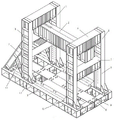
The utility model belongs to the technical field of civil engineering structure, concretely relates to full assembly type steel construction reaction frame, including "worker" style of calligraphy stand, longeron and crossbeam, the crossbeam include a plurality of entablature and a plurality of first bottom end rail, the longeron includes parallel arrangement's three horizontal bottom longeron, and is three bottom end rail department is respectively through first bottom end rail rather than perpendicular fixed connection, two of both sides bottom end rail on fixed two stands respectively, two liang of corresponding settings of stand on two bottom end rails respectively, and two bottom end rails on correspond the setting the stand on two liang of between the tip respectively through entablature fixed connection, two entablature lower fixed surface be provided with rather than vertically well longeron, well longeron cross-section be the box. The reaction frame not only meets the loading test of model test pieces with different sizes, but also meets the multi-direction and multi-node loading, is convenient to carry and move, and meets the loading requirements of indoor and outdoor tests, even inside and outside saving tests.
Description
Technical Field
The utility model belongs to the technical field of civil engineering structure, concretely relates to full assembly type steel construction reaction frame.
Background
The main function of the reaction frame is to provide reaction support for the structure in the structure test, so that the test is ensured to be carried out safely and smoothly. The reaction frame has the advantages of simple structure, concise force transmission, convenient installation, repeated utilization and enough strength, rigidity and stability. With the development of the space structure, the forms and the types of the nodes are more and more. Since the damage of the node is usually directly caused to the damage of the whole structure, various large-scale projects put higher requirements on the bearing capacity of the node. Usually, the counterforce frame only provides vertical or horizontal loading counterforce, and the unicity of the counterforce application direction cannot adapt to the requirement of the modern structural node test.
The existing reaction frame is usually fixed together with a base and a concrete table base by using an earth anchor bolt in order to guarantee the stability of the reaction frame and the accuracy when pulling or pressing various concrete members and large-scale workpieces, the mode can cause the reaction frame to be difficult to disassemble and carry, and the reaction frame needs to be embedded into a channel on the ground of a structure experiment building and does not meet the requirement of the reaction loading of a construction site of a building structure. In addition, the existing reaction frame has high bearing capacity requirement on a foundation at a placing position, and has certain size requirement on a pressure application model test piece due to the fixed size of a channel, and the defects finally influence the development process of the reaction frame.
Patent document No. CN108398250A discloses a combined steel structure reaction frame, which comprises four identical door type reaction frames, an annular beam, a slider and a top combined member, wherein the four identical door type reaction frames use the center of a beam at the top of the door type reaction frame as a circular point, and are arranged in a forty-five degree included angle array, each door type reaction frame comprises an upright post and a beam, the middle part of the beam of each door type reaction frame is disconnected by a certain distance, and the top combined member is embedded in the disconnected part using the circular point as the center; the ring beam is connected with each beam through a steel plate fixed at the bottom of each beam, and the sliding block is arranged on the ring beam. This reaction frame can realize simultaneously in the common loading of the space slant of the three hundred sixty degrees simultaneous vertical thirty degrees to fifty degrees within ranges of a plurality of directions of level, vertical and along the level three hundred sixty degrees, can satisfy the test demand of structure and node basically, but this reaction frame exists to support insecure, needs to be fixed in ground through the rag crab-bolt, and this kind of mode transport is dismantled more difficultly, can not satisfy the building structure job site counter-force loading requirement.
Disclosure of Invention
An object of the utility model is to provide a problem that exists among the prior art provides a full assembled steel construction reaction frame, this reaction frame is applicable to job site model test, no counter-force groove or counter-force floor structure laboratory, does not need the special treatment ground, the full assembly of component, the adjustment reaction frame space of being convenient for had both satisfied not unidimensional model test piece loading test, satisfy multi-direction, the multinode loading again, be convenient for simultaneously transport, remove, satisfy indoor outer province inside and outside test loading demand even.
The technical scheme of the utility model is that:
the utility model provides a full assembled steel construction reaction frame, includes "worker" style of calligraphy stand, longeron and "worker" style of calligraphy crossbeam, the crossbeam include a plurality of entablature and a plurality of first end crossbeam, the longeron includes parallel arrangement's three horizontal bottom longeron, it is three end longeron end department is respectively through first end crossbeam rather than vertical fixed connection, two of both sides end longeron on fix respectively and be provided with two stands, two liang of corresponding settings respectively of stand on two end longerons, and two last corresponding settings of two end longerons the stand on two liang between the tip respectively through entablature fixed connection, two entablature lower fixed surface be provided with rather than vertically well longeron, well longeron include well longeron pterygoid lamina and well longeron web, well longeron pterygoid lamina and well longeron web formation well longeron.
Specifically, two second bottom cross beams are fixedly arranged between the two bottom longitudinal beams, the two second bottom cross beams are respectively arranged corresponding to the stand columns, and the second bottom cross beams are respectively fixedly connected with the bottom longitudinal beams.
The two inclined struts are obliquely arranged on the end parts of the bottom longitudinal beams respectively and are fixedly connected with two adjacent upright columns which are correspondingly arranged respectively; the bottom parts of the two inclined struts are respectively fixedly arranged on the bottom longitudinal beam, and the top parts of the two inclined struts are respectively fixedly connected with the upright post.
Specifically, two stiffening inclined struts are respectively arranged between the inclined struts and the bottom longitudinal beam, one end of each stiffening inclined strut is fixedly connected with the middle part of the corresponding inclined strut, and the other end of each stiffening inclined strut is close to the corresponding upright column and is fixedly connected with the corresponding bottom longitudinal beam.
Specifically, the middle parts of the two upright columns, which are correspondingly arranged on the two bottom longitudinal beams, between each two upright columns are respectively provided with a middle cross beam, and two end parts of the middle cross beam are respectively fixedly connected with the upright columns.
Specifically, the joints of the upright columns and the bottom longitudinal beams are respectively provided with a trapezoidal stiffening plate, each upright column comprises a web plate and two wing plates, and a plurality of stiffening plates are fixedly arranged between the two wing plates.
The cross beam is I-shaped and comprises a web plate and two wing plates, and a plurality of stiffening plates are fixedly arranged between the two wing plates.
Specifically, the bottom longitudinal beam is I-shaped and comprises a web plate and two wing plates, and a plurality of stiffening plates are fixedly arranged between the two wing plates.
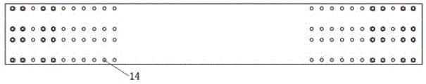
Specifically, a plurality of bolt holes which are arranged at equal intervals are arranged on a wing plate of the bottom longitudinal beam, a plurality of bolt holes are arranged on a web plate of the upright post close to the inclined strut at equal intervals within a range from bottom to top within a range from 0.2m to 2.5m from the bottom, a plurality of bolt holes are arranged on a web plate of the upright post far away from the inclined strut at equal intervals within a range from bottom to top within a range from 0.3m to 2.4m from the bottom, and a plurality of bolt holes are arranged on a web plate of the upright post at equal intervals within a range from bottom to top within a range from 0.5 m; a plurality of bolt holes are respectively arranged at equal intervals from the end part to the 1m position of each of two ends of a wing plate of the middle longitudinal beam, and the upright columns are respectively and fixedly connected with the cross beam, the middle cross beam and the bottom longitudinal beam through high-strength bolts penetrating into the bolt holes; the cross beam and the middle longitudinal beam are respectively fixedly connected through high-strength bolts penetrating into bolt holes; the first bottom cross beam and the bottom longitudinal beam are fixedly connected through high-strength bolts penetrating into bolt holes respectively; the bottom longitudinal beam and the inclined strut are respectively and fixedly connected through high-strength bolts penetrating through bolt holes, the cross beam and the stand are fixedly connected through high-strength bolts penetrating through bolt holes, and the second bottom cross beam is respectively and fixedly connected with the bottom longitudinal beam through high-strength bolts penetrating through bolt holes.
Specifically, the flanges are welded at the connecting positions when the steel beams are connected through the high-strength bolts.
The utility model has the advantages that: the reaction frame comprises upright columns, a middle longitudinal beam, a bottom longitudinal beam, a cross beam, a middle cross beam, a first bottom cross beam, a second bottom cross beam, an inclined strut, a stiffening plate, a high-strength bolt and a flange, wherein the section of the middle longitudinal beam is in a box shape, the section of other steel beams are in an I shape, and adjacent steel beams are connected through the high-strength bolt, so that the component is fully assembled, the reaction frame is convenient to manufacture, install and disassemble, and can meet the loading requirement of an outdoor experiment; and the middle longitudinal beam is arranged on the lower surface of the upper cross beam, and when the reaction frame vertically loads a test piece, the upper cross beam effectively prevents the test piece from centering on the upward reaction force of the longitudinal beam, so that the normal use of the fully-assembled reaction frame is ensured.
The method for arranging the bolt holes at equal intervals can enable the upright post, the middle longitudinal beam and the bottom longitudinal beam to flexibly change the positions of high-strength bolt connection, so that the position of the middle cross beam along the length direction of the upright post beam, the distance between the upright post and the bottom longitudinal beam along the length direction of the bottom longitudinal beam and the loading length of the middle longitudinal beam along the length direction of the middle longitudinal beam are adjusted, the loading test of model test pieces with different sizes is met, and multi-direction multi-node loading is also met. Through the arrangement of the bolt holes, the positions of the stand columns and the inclined struts on the bottom longitudinal beam can be flexibly changed, so that the space of the reaction frame can be adjusted, the loading test of model test pieces with different sizes is met, and the multi-direction and multi-node loading is also met.
The reinforcing plates are welded on two sides of the web plate of each steel beam at intervals, the reinforcing plates are arranged according to the principle that concentrated load positions are encrypted and load positions are not encrypted, the arrangement mode can better utilize materials, and meanwhile, the economy is higher.
The utility model provides a connected mode of reaction frame is convenient for make, installation, dismantlement, practices thrift the cost. The reaction frame is of a self-structural system, is not required to be connected with the ground through an earth anchor bolt, and has no special requirement on the bearing capacity of a foundation, so that the loading requirement of an outdoor experiment is met; the middle longitudinal beam, the cross beam and two sides of the middle cross beam are used for arranging stiffening plates in a way of encrypting the middle area along the beam length direction according to the arrangement requirements of the stiffening plates, so that the safety is high, and the economical efficiency is good; the positions of the upright post, the middle longitudinal beam and the bottom longitudinal beam can be adjusted by a method of pre-arranging bolt holes according to bolt hole arrangement requirements, so that the loading test of model test pieces with different sizes is met, and multi-direction multi-node loading is also met.
Drawings
Fig. 1 is a schematic view of the structure of the present invention;
FIG. 2 is a schematic top view of the structure of FIG. 1;
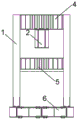
FIG. 3 is a side view of the structure of FIG. 1;
FIG. 4 is a schematic front view of the structure of FIG. 1;
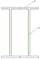
FIG. 5 is a front view of the middle longitudinal beam;
FIG. 6 is a schematic top view of a longitudinal beam;
fig. 7 is a cross-sectional structural diagram of the middle longitudinal beam.
1. The structure comprises upright columns, 2. middle longitudinal beams, 3. bottom longitudinal beams, 4. upper cross beams, 5. middle cross beams, 6. first bottom cross beams, 7. diagonal braces, 8. stiffening plates, 9. high-strength bolts, 10. flanges, 11 second bottom cross beams, 12 trapezoidal stiffening plates, 13 stiffening diagonal braces, 14 bolt holes, 15 middle longitudinal beam webs and 16 middle longitudinal beam wing plates.
Detailed Description
The present invention will be described in detail with reference to the following embodiments and accompanying drawings.
Example 1
As shown in fig. 1-4, the structural schematic diagram of a fully assembled steel structural reaction frame provided in this embodiment is that the reaction frame includes "i" shaped columns, longitudinal beams, and "i" shaped beams, where the beams include a plurality of upper beams 4 and a plurality of first bottom beams 6, the longitudinal beams include two horizontal bottom longitudinal beams 3 arranged in parallel, two ends of the two bottom longitudinal beams 3 are respectively and fixedly connected to the vertical ends of the two bottom longitudinal beams through the first bottom beams 6, two columns 1 are respectively and fixedly arranged on each bottom longitudinal beam 3, the columns 1 on the two bottom longitudinal beams 3 are respectively arranged in pairs and correspondingly, two ends of the columns 1 correspondingly arranged on the two bottom longitudinal beams 3 are respectively and fixedly connected to each other through the upper beams 4, middle longitudinal beams 2 perpendicular to the two upper beams 4 are fixedly arranged on the lower surfaces of the two upper beams 4, the middle longitudinal beams 2 include middle longitudinal beam wing plates 16 and middle longitudinal beam webs 15, the section of the middle longitudinal beam 2 formed by the middle longitudinal beam wing plate 16 and the middle longitudinal beam web plate 15 is box-shaped, as shown in fig. 5, 6 and 7, the structure schematic diagram of the middle longitudinal beam 2 is shown, the middle longitudinal beam 2 is arranged on the lower surface of the upper cross beam 4, and the upper cross beam 4 effectively prevents a test piece from upwards reacting to the middle longitudinal beam 2 when the reaction frame vertically loads the test piece, so that the normal use of the fully-assembled reaction frame is ensured. The two inclined struts 7 are respectively obliquely arranged on the end parts of the bottom longitudinal beams 3 and are respectively and fixedly connected with two adjacent upright posts 1 which are correspondingly arranged; the bottoms of the two inclined struts 7 are respectively fixedly arranged on the bottom longitudinal beam 3, and the tops of the two inclined struts 7 are respectively fixedly connected with the upright post 1. Two bracing 7 and end longeron 3 between be provided with stiffening diagonal 13 respectively, every stiffening diagonal 13 one end and its bracing 7 middle part fixed connection that corresponds, the other end closely adjacent rather than stand 1 that corresponds and with corresponding end longeron 3 fixed connection. The setting of the diagonal bracing 7 further increases the bearing capacity of the reaction frame.
Two second bottom cross beams 11 are fixedly arranged between the two bottom longitudinal beams 3, the two second bottom cross beams 11 are respectively arranged corresponding to the upright posts 1, and the second bottom cross beams 11 are respectively fixedly connected with the bottom longitudinal beams 3. The middle parts between every two upright posts 1 correspondingly arranged on the two bottom longitudinal beams 3 are respectively provided with a middle cross beam 5, and two end parts of the middle cross beam 5 are respectively fixedly connected with the upright posts 1. And flanges 10 are welded at the connecting positions when the high-strength bolts 9 are connected between the steel beams. The cross beam is I-shaped and comprises a web plate and two wing plates, and a plurality of stiffening plates 8 are fixedly arranged between the two wing plates. The bottom longitudinal beam 3 is I-shaped and comprises a web plate and two wing plates, a plurality of stiffening plates 8 are fixedly arranged between the two wing plates, the stiffening plates 8 are arranged according to the principle that concentrated load positions are encrypted and load positions are not encrypted, the arrangement mode can better utilize materials, and meanwhile, the economy is higher.
The vertical column 1 and the bottom longitudinal beam 3 are respectively provided with trapezoidal stiffening plates 12 at the joints, the vertical column 1 comprises a web plate and two wing plates, a plurality of stiffening plates 8 are fixedly arranged between the two wing plates, the stiffening plates 8 are arranged according to the principle that the concentrated load part is encrypted and the load part is smaller is not encrypted, the arrangement mode can better utilize materials, and meanwhile, the economical efficiency is higher.
A plurality of bolt holes 14 which are arranged at equal intervals are arranged on a wing plate of the bottom longitudinal beam 3, a plurality of bolt holes 14 which are arranged at equal intervals in a range from bottom to top from 0.2m to 2.5m from the bottom end are arranged on a web plate of the upright post 1 which is close to the inclined strut 7, a plurality of bolt holes 14 which are arranged at equal intervals in a range from bottom to top from 0.3m to 2.4m from the bottom end are arranged on a web plate of the upright post 1 which is far away from the inclined strut 7, and a plurality of bolt holes 14 are arranged at equal intervals in a range from bottom to top from the web plate of the upright post 1; a plurality of bolt holes 14 are respectively arranged at two ends of a middle longitudinal beam wing plate 16 of the middle longitudinal beam 2 at equal intervals from the end part to the position 1m, and the upright column 1 is fixedly connected with the cross beam 4, the middle cross beam 5 and the bottom longitudinal beam 3 through the bolt holes 14 which are respectively penetrated by high-strength bolts 9; the cross beam 4 and the middle longitudinal beam 2 are fixedly connected through a bolt hole 14 through a high-strength bolt 9; the first bottom cross beam 6 and the bottom longitudinal beam 3 are fixedly connected through a high-strength bolt 9 penetrating into a bolt hole 14; the bottom longitudinal beam 3 and the inclined strut 7 are fixedly connected through high-strength bolts 9 penetrating through bolt holes 14 respectively, and the second bottom cross beam 11 is fixedly connected with the bottom longitudinal beam 3 through high-strength bolts 9 penetrating through the bolt holes 14 respectively. The method for arranging the bolt holes 14 at equal intervals can enable the upright post 1, the middle longitudinal beam 2 and the bottom longitudinal beam 3 to flexibly change the connection positions of the high-strength bolts 9, so that the position of the middle cross beam 5 along the beam length direction of the upright post 1, the distance between the upright post 1 along the beam length direction of the bottom longitudinal beam 3 and the loading length of the middle longitudinal beam 2 along the beam length are adjusted, and not only is the loading test of model test pieces with different sizes met, but also the multi-direction multi-node loading is met. Through the arrangement of the bolt holes 14, the positions of the upright posts 1 and the inclined struts 7 on the bottom longitudinal beams 3 can also be flexibly changed, so that the space of a reaction frame can be adjusted, the loading test of model test pieces with different sizes is met, and the multi-direction and multi-node loading is met.
Finally, it should be noted that the above embodiments are only used for illustrating the technical solutions of the present invention and not for limiting the same; although the present invention has been described in detail with reference to preferred embodiments, it should be understood by those skilled in the art that: the invention can be modified or equivalent substituted for some technical features; without departing from the spirit of the present invention, it should be understood that the scope of the claims is intended to cover all such modifications and variations.
Claims (10)
1. A full-assembly steel structure reaction frame comprises I-shaped columns, longitudinal beams and I-shaped beams, and is characterized in that the beams comprise a plurality of upper cross beams (4) and a plurality of first bottom cross beams (6), each longitudinal beam comprises three horizontal bottom longitudinal beams (3) which are arranged in parallel, the ends of the three bottom longitudinal beams (3) are respectively and fixedly connected with the vertical ends of the three horizontal bottom longitudinal beams through the first bottom cross beams (6), two bottom longitudinal beams (3) on two sides are respectively and fixedly provided with two columns (1), the columns (1) on the two bottom longitudinal beams (3) are respectively arranged in pairs in a corresponding manner, the ends of the two corresponding columns (1) on the two bottom longitudinal beams (3) are respectively and fixedly connected with each other through the upper cross beams (4), the lower surfaces of the two upper cross beams (4) are fixedly provided with middle longitudinal beams (2) which are vertical to the two bottom longitudinal beams, each middle longitudinal beam (2) comprises a middle longitudinal beam wing plate (16) and a middle longitudinal beam web plate, the section of the middle longitudinal beam (2) formed by the middle longitudinal beam wing plate (16) and the middle longitudinal beam web plate (15) is box-shaped.
2. The fully assembled steel structure reaction frame according to claim 1, wherein two second bottom cross beams (11) are fixedly arranged between the two bottom longitudinal beams (3), the two second bottom cross beams (11) are respectively arranged corresponding to the upright posts (1), and the second bottom cross beams (11) are respectively and fixedly connected with the bottom longitudinal beams (3).
3. The fully assembled steel structure reaction frame according to claim 2, further comprising two inclined struts (7), wherein the two inclined struts (7) are respectively obliquely arranged on the end parts of the bottom longitudinal beams (3) and are respectively and fixedly connected with two adjacent corresponding upright columns (1); the bottoms of the two inclined struts (7) are respectively fixedly arranged on the bottom longitudinal beam (3), and the tops of the two inclined struts (7) are respectively fixedly connected with the upright post (1).
4. The fully assembled steel structure reaction frame according to claim 3, wherein stiffening inclined struts (13) are respectively arranged between the two inclined struts (7) and the bottom longitudinal beam (3), one end of each stiffening inclined strut (13) is fixedly connected with the middle part of the corresponding inclined strut (7), and the other end of each stiffening inclined strut is closely adjacent to the corresponding upright post (1) and is fixedly connected with the corresponding bottom longitudinal beam (3).
5. The fully assembled steel structure reaction frame according to claim 4, wherein the middle part between every two upright columns (1) correspondingly arranged on the two bottom longitudinal beams (3) is respectively provided with a middle cross beam (5), and two end parts of the middle cross beam (5) are respectively and fixedly connected with the upright columns (1).
6. The fully assembled steel structure reaction frame according to claim 5, wherein trapezoidal stiffening plates (12) are respectively arranged at the joints of the upright columns (1) and the bottom longitudinal beams (3), each upright column (1) comprises a web plate and two wing plates, and a plurality of stiffening plates (8) are fixedly arranged between the two wing plates.
7. The fully assembled steel structure reaction frame according to claim 6, wherein the cross beam is I-shaped and comprises a web plate and two wing plates, and a plurality of stiffening plates (8) are fixedly arranged between the two wing plates.
8. The fully assembled steel structure reaction frame according to claim 7, wherein the bottom longitudinal beam (3) is I-shaped and comprises a web plate and two wing plates, and a plurality of stiffening plates (8) are fixedly arranged between the two wing plates.
9. The fully assembled steel structure reaction frame according to claim 8, wherein a plurality of bolt holes (14) are arranged on the wing plate of the bottom longitudinal beam (3) at equal intervals, a plurality of bolt holes (14) are arranged on the web plate of the upright post (1) close to the inclined strut (7) at equal intervals within the range of 0.2m to 2.5m from bottom to top from the bottom end, a plurality of bolt holes (14) are arranged on the web plate of the upright post (1) far away from the inclined strut (7) at equal intervals within the range of 0.3m to 2.4m from bottom to top from the bottom end, and a plurality of bolt holes (14) are arranged on the web plate of the upright post (1) at equal intervals within the range of 0.5m from bottom to top; a plurality of bolt holes (14) are respectively arranged at equal intervals from the end part to the 1m position at two ends of a middle longitudinal beam wing plate (16) of the middle longitudinal beam (2), and the upright column (1) is fixedly connected with the upper cross beam (4), the middle cross beam (5) and the bottom longitudinal beam (3) through the bolt holes (14) which are respectively penetrated through high-strength bolts (9); the upper cross beam (4) and the middle longitudinal beam (2) are fixedly connected through a bolt hole (14) through a high-strength bolt (9); the first bottom cross beam (6) and the bottom longitudinal beam (3) are fixedly connected through a bolt hole (14) through a high-strength bolt (9); the bottom longitudinal beam (3) and the inclined strut (7) are fixedly connected through a bolt hole (14) which is penetrated by a high-strength bolt (9), and the second bottom cross beam (11) is fixedly connected with the bottom longitudinal beam (3) through a bolt hole (14) which is penetrated by a high-strength bolt (9).
10. The fully assembled steel structure reaction frame according to claim 9, wherein the vertical column (1) and the upper cross beam (4), the middle cross beam (5) and the bottom longitudinal beam (3) are welded with the flange (10) at the connecting position with the high-strength bolt (9), the first bottom cross beam (6), the bottom longitudinal beam (3) and the high-strength bolt (9) are welded with the flange (10) at the connecting position, and the bottom longitudinal beam (3), the diagonal brace (7) and the high-strength bolt (9) are welded with the flange (10) at the connecting position.
Priority Applications (1)
| Application Number | Priority Date | Filing Date | Title |
|---|---|---|---|
| CN201921619123.8U CN210603852U (en) | 2019-09-26 | 2019-09-26 | Full-assembly type steel structure reaction frame |
Applications Claiming Priority (1)
| Application Number | Priority Date | Filing Date | Title |
|---|---|---|---|
| CN201921619123.8U CN210603852U (en) | 2019-09-26 | 2019-09-26 | Full-assembly type steel structure reaction frame |
Publications (1)
| Publication Number | Publication Date |
|---|---|
| CN210603852U true CN210603852U (en) | 2020-05-22 |
Family
ID=70693413
Family Applications (1)
| Application Number | Title | Priority Date | Filing Date |
|---|---|---|---|
| CN201921619123.8U Expired - Fee Related CN210603852U (en) | 2019-09-26 | 2019-09-26 | Full-assembly type steel structure reaction frame |
Country Status (1)
| Country | Link |
|---|---|
| CN (1) | CN210603852U (en) |
Cited By (3)
| Publication number | Priority date | Publication date | Assignee | Title |
|---|---|---|---|---|
| CN113970431A (en) * | 2021-10-22 | 2022-01-25 | 中国铁道科学研究院集团有限公司标准计量研究所 | Multichannel contact net spare part fatigue test device |
| CN114295334A (en) * | 2021-10-14 | 2022-04-08 | 天津大学 | Fatigue test platform device and analysis method for foot-size orthotropic steel bridge deck slab |
| CN116380440A (en) * | 2023-04-19 | 2023-07-04 | 昆山市建设工程质量检测中心 | Movable reaction frame for performance test of prefabricated staircase structure |
-
2019
- 2019-09-26 CN CN201921619123.8U patent/CN210603852U/en not_active Expired - Fee Related
Cited By (5)
| Publication number | Priority date | Publication date | Assignee | Title |
|---|---|---|---|---|
| CN114295334A (en) * | 2021-10-14 | 2022-04-08 | 天津大学 | Fatigue test platform device and analysis method for foot-size orthotropic steel bridge deck slab |
| CN113970431A (en) * | 2021-10-22 | 2022-01-25 | 中国铁道科学研究院集团有限公司标准计量研究所 | Multichannel contact net spare part fatigue test device |
| CN113970431B (en) * | 2021-10-22 | 2023-02-17 | 中国铁道科学研究院集团有限公司标准计量研究所 | Multichannel contact net spare part fatigue test device |
| CN116380440A (en) * | 2023-04-19 | 2023-07-04 | 昆山市建设工程质量检测中心 | Movable reaction frame for performance test of prefabricated staircase structure |
| CN116380440B (en) * | 2023-04-19 | 2024-01-26 | 昆山市建设工程质量检测中心 | Movable reaction frame for performance test of prefabricated staircase structure |
Similar Documents
| Publication | Publication Date | Title |
|---|---|---|
| CN210603852U (en) | Full-assembly type steel structure reaction frame | |
| CN110306658B (en) | Steel structure assembly system for assembly type building and construction method | |
| CN105780925A (en) | Method for installation construction of truss-hanging combination system | |
| CN108560895B (en) | Adjustable elevator shaft operation platform and erection method thereof | |
| CN103498509A (en) | Steel structure combined column system and connecting method thereof | |
| CN114411970A (en) | Beam column node structure of steel construction assembly type structure | |
| CN102261043B (en) | Assembled steel pipe upright post system | |
| CN204080843U (en) | Movable plank house foundation structure | |
| CN104032829A (en) | Modularized high-rise assembled steel structure pre-stressed eccentric support system | |
| CN110748063B (en) | Assembled steel bar truss floor support plate with support | |
| CN102175475B (en) | Kiloton modular combined adjustable self-reaction table frame device | |
| CN104674949A (en) | Portable shelter | |
| CN207905104U (en) | A kind of assembled architecture truss structure | |
| CN202152442U (en) | Assembling type steel tube-vertical post system | |
| CN102864746A (en) | Bearing frame for bridge construction | |
| CN202831628U (en) | Combined type bailey frame load-bearing shelving for pouring large span concrete beam | |
| CN202049034U (en) | Kiloton modularized combined adjustable self-balancing reaction frame device | |
| CN103758342A (en) | Tool-type top form for buildings | |
| CN214062433U (en) | Temporary supporting structure of assembled steel structure | |
| CN108204039A (en) | A kind of assembled architecture truss structure | |
| CN211690769U (en) | Steel structure supporting node component | |
| CN203225074U (en) | Advertising board of net rack structure | |
| CN113137102A (en) | Assembled type warehouse roof structure and installation method thereof | |
| CN112681518A (en) | Steel construction assembled beam column node connecting device | |
| CN212801953U (en) | Steel construction is assembled atress and is converted bed-jig device |
Legal Events
| Date | Code | Title | Description |
|---|---|---|---|
| GR01 | Patent grant | ||
| GR01 | Patent grant | ||
| CF01 | Termination of patent right due to non-payment of annual fee |
Granted publication date: 20200522 Termination date: 20200926 |
|
| CF01 | Termination of patent right due to non-payment of annual fee |