CN112644757A - Copper coil pipe packing machine - Google Patents
Copper coil pipe packing machine Download PDFInfo
- Publication number
- CN112644757A CN112644757A CN202011593173.0A CN202011593173A CN112644757A CN 112644757 A CN112644757 A CN 112644757A CN 202011593173 A CN202011593173 A CN 202011593173A CN 112644757 A CN112644757 A CN 112644757A
- Authority
- CN
- China
- Prior art keywords
- workpiece
- roller
- conveying
- packaging
- label
- Prior art date
- Legal status (The legal status is an assumption and is not a legal conclusion. Google has not performed a legal analysis and makes no representation as to the accuracy of the status listed.)
- Granted
Links
Images


Classifications
-
- B—PERFORMING OPERATIONS; TRANSPORTING
- B65—CONVEYING; PACKING; STORING; HANDLING THIN OR FILAMENTARY MATERIAL
- B65B—MACHINES, APPARATUS OR DEVICES FOR, OR METHODS OF, PACKAGING ARTICLES OR MATERIALS; UNPACKING
- B65B11/00—Wrapping, e.g. partially or wholly enclosing, articles or quantities of material, in strips, sheets or blanks, of flexible material
- B65B11/04—Wrapping, e.g. partially or wholly enclosing, articles or quantities of material, in strips, sheets or blanks, of flexible material the articles being rotated
- B65B11/045—Wrapping, e.g. partially or wholly enclosing, articles or quantities of material, in strips, sheets or blanks, of flexible material the articles being rotated by rotating platforms supporting the articles
-
- B—PERFORMING OPERATIONS; TRANSPORTING
- B65—CONVEYING; PACKING; STORING; HANDLING THIN OR FILAMENTARY MATERIAL
- B65B—MACHINES, APPARATUS OR DEVICES FOR, OR METHODS OF, PACKAGING ARTICLES OR MATERIALS; UNPACKING
- B65B35/00—Supplying, feeding, arranging or orientating articles to be packaged
- B65B35/10—Feeding, e.g. conveying, single articles
- B65B35/22—Feeding, e.g. conveying, single articles by roller-ways
-
- B—PERFORMING OPERATIONS; TRANSPORTING
- B65—CONVEYING; PACKING; STORING; HANDLING THIN OR FILAMENTARY MATERIAL
- B65B—MACHINES, APPARATUS OR DEVICES FOR, OR METHODS OF, PACKAGING ARTICLES OR MATERIALS; UNPACKING
- B65B35/00—Supplying, feeding, arranging or orientating articles to be packaged
- B65B35/56—Orientating, i.e. changing the attitude of, articles, e.g. of non-uniform cross-section
-
- B—PERFORMING OPERATIONS; TRANSPORTING
- B65—CONVEYING; PACKING; STORING; HANDLING THIN OR FILAMENTARY MATERIAL
- B65C—LABELLING OR TAGGING MACHINES, APPARATUS, OR PROCESSES
- B65C9/00—Details of labelling machines or apparatus
- B65C9/08—Label feeding
- B65C9/18—Label feeding from strips, e.g. from rolls
- B65C9/1803—Label feeding from strips, e.g. from rolls the labels being cut from a strip
-
- B—PERFORMING OPERATIONS; TRANSPORTING
- B65—CONVEYING; PACKING; STORING; HANDLING THIN OR FILAMENTARY MATERIAL
- B65C—LABELLING OR TAGGING MACHINES, APPARATUS, OR PROCESSES
- B65C9/00—Details of labelling machines or apparatus
- B65C9/26—Devices for applying labels
- B65C9/30—Rollers
Abstract
The invention relates to the technical field of coil production and processing, in particular to a copper coil packaging machine which comprises a supporting mechanism, a conveying mechanism, a hoisting mechanism, a packaging mechanism and a labeling mechanism, wherein the supporting mechanism is used for supporting a workpiece and driving the workpiece to rotate, the conveying mechanism is used for conveying the workpiece to the supporting mechanism, the hoisting mechanism is used for hoisting the workpiece, the packaging mechanism is used for winding a packaging tape on the workpiece, the labeling mechanism is used for labeling the workpiece after packaging, the supporting mechanism is arranged on the conveying mechanism, and the labeling mechanism is arranged on one side of the conveying mechanism. The invention not only can package the workpiece, but also can label the workpiece after the packaging is finished, the packaging and the labeling are finished by the same equipment, the equipment conversion is not needed, and the problem that the existing packaging machine can not label the copper coil pipe is solved.
Description
Technical Field
The invention relates to the technical field of coil pipe production and processing, in particular to a copper coil pipe packaging machine.
Background
Copper coil pipe, the copper pipe that spirals into circle dish together promptly, in the actual production, for convenient transportation and deposit, can transport the sale after processing into copper coil pipe with the copper pipe.
In actual production, need pack and beat the mark after copper coil pipe production is accomplished, twine on copper coil pipe with the packing band to transport, avoid copper coil pipe to damage. Still need paste round label paper in copper coil's the outside after the packing is accomplished, adopt packagine machine to pack copper coil at present more, present packagine machine only can pack copper coil, can't accomplish and paste the mark for paste the mark process and need wait for extra going on after the packing is accomplished, seriously influenced copper coil's production efficiency.
Disclosure of Invention
The invention aims to provide a copper coil pipe packing machine to solve the problem that the existing packing machine cannot label a copper coil pipe.
In order to achieve the purpose, the invention provides the following technical scheme:
the copper coil pipe packing machine comprises a supporting mechanism used for supporting a workpiece and driving the workpiece to rotate, a conveying mechanism used for conveying the workpiece to the supporting mechanism, a hoisting mechanism used for hoisting the workpiece, a packing mechanism used for winding a packing belt on the workpiece and a labeling mechanism used for labeling the workpiece, wherein the supporting mechanism is arranged on the conveying mechanism, and the labeling mechanism is arranged on one side of the conveying mechanism.
The principle and the beneficial effect of the scheme are as follows:
the hoisting mechanism is used for hoisting the workpiece to the conveying mechanism or hoisting the workpiece from the conveying mechanism to realize feeding and discharging of the workpiece, and in addition, the hoisting mechanism can also realize automatic stacking and stacking of the workpiece after discharging. The conveying mechanism conveys the workpiece to the supporting mechanism, the packaging mechanism winds the packaging belt on the workpiece, and meanwhile, the supporting mechanism drives the workpiece to rotate, so that the workpiece is packaged; after the workpiece rotates for a circle and a half, namely when the part of the workpiece wound with the packaging tape rotates to the labeling mechanism, a circle of labels can be pasted on the outer side of the workpiece through the labeling mechanism, and the labeling of the workpiece is realized. The scheme can be used for packaging the workpiece, labeling can be performed on the workpiece after the packaging is completed, the packaging and labeling are completed by the same equipment, conversion equipment is not needed, and the processing efficiency is improved.
Furthermore, the supporting mechanism comprises a plurality of transversely arranged supporting rollers, the supporting rollers are connected with a rotating motor, the supporting rollers are further connected with a lifting cylinder for driving the supporting rollers to lift, the supporting rollers form an annular shape in a surrounding mode, the supporting rollers are conical, and the small-diameter ends of the supporting rollers face towards the center of the annular circle.
Has the advantages that: after the supporting roller is lifted, the workpiece can be lifted to support the workpiece; the rotating motor is used for driving the supporting roller to rotate so as to drive the workpiece to rotate, the conical supporting roller is adopted, the small-diameter end of the supporting roller faces inwards, radial movement of the workpiece during rotation can be avoided, and stability of rotation of the workpiece is improved.
Furthermore, at least two centering rollers are arranged above the supporting mechanism, the centering rollers are connected with a centering cylinder used for driving the centering cylinder to lift, a positioning roller used for being connected with the centering rollers is arranged on the conveying mechanism, the centering rollers are vertically arranged, and the roller surfaces of the centering rollers can be in contact with the inner wall of the workpiece.
Has the advantages that: after the workpiece is conveyed to the supporting mechanism, the centering cylinder drives the centering roller to move downwards, and the centering roller is inserted into the workpiece ring and is connected with the positioning roller, so that the workpiece can accurately reach a preset position, namely, the workpiece is centered; in the rotating process of the workpiece, the centering roller is in contact with the inner wall of the workpiece, the workpiece can be centered in real time, the workpiece is prevented from deviating, and the structure is simple.
Furthermore, the labeling mechanism is arranged in a sliding manner and can be close to or far away from the workpiece; the labeller constructs including the fixed subassembly that is used for fixed label free end, the cutter that is used for cutting the label, be used for compressing tightly the compression roller on the work piece outer wall with the label roller that is used for fixed label, fixed subassembly sets up the one side that is close to supporting mechanism at the label roller, and the compression roller setting is in the one side that fixed subassembly is close to supporting mechanism, and the compression roller rotates the setting, and the cutter slides and sets up between fixed subassembly and compression roller, and the cutter is connected with the cutting cylinder.
Has the advantages that: the label is wound on the label roller, the labeling mechanism is driven to move towards the workpiece after the head of the label is fixed on the fixing assembly, the head of the label is pressed on the workpiece by the pressing roller, the workpiece is driven to rotate by the supporting roller, the label can be attached to the outer ring of the workpiece, and the cutter is driven to move towards the workpiece after cutting is finished, so that the label can be cut off, and labeling is completed.
Further, fixed subassembly includes the fixing base, the one end that the label roller was kept away from to the fixing base is rotated and is provided with the fixed roller, the fixing base side is provided with the fixed plate, the one end of fixed plate is tangent with the roll surface of fixed roller, form the passageway that supplies the label to pass between fixed plate and the fixing base, the width of passageway reduces to the other end from the one end that the fixing base is close to the label roller gradually, it is provided with the guide roll to rotate between fixing base and the label roller, it is provided with spacing roller to rotate between fixed roller and the cutter, the roll surface of spacing roller can offset with the outer wall of work piece, the label can the tensioning.
Has the advantages that: the label is threaded from the channel to the fixing roller in a state that the adhesive surface faces outwards, and the free end of the label can be clamped between the fixing plate and the fixing roller due to the fact that the fixing plate is tangent to the fixing roller, and therefore the free end of the label is fixed.
Further, one side that the fixing base was equipped with the fixed plate is provided with the arch, and the arch sets up along the direction of transfer of label, also is provided with the arch on the fixed roll surface, and the fixed plate is seted up towards the one end of fixed roll and is dodged the bellied hole of dodging on the fixed roll.
Has the advantages that: the upper side and the lower side of the label can be bent towards the direction close to the fixed seat by arranging the bulge, so that the contact area between the label pasting surface and the fixed plate is reduced, and the label pasting surface is prevented from being polluted; in addition, the label can be better fixed after being bent, and the fixing effect is improved; the arrangement of the avoiding hole does not influence the tangency of the fixed plate and the fixed roller.
Furthermore, the packaging mechanism comprises a C-shaped rotary table, a conveying assembly and a shearing assembly, wherein the conveying assembly is used for clamping the packaging belt and conveying the packaging belt to the rotary table, the shearing assembly is used for shearing the packaging belt, the rotary table is connected with a driving assembly used for driving the rotary table to rotate, and a plurality of belt rollers are vertically arranged on the disc surface of the rotary table.
Has the advantages that: the conveying assembly clamps the end of the packaging tape and conveys the packaging tape to the rotary table, the rotary table is driven to rotate, the packaging tape is hooked by the tape roller on the rotary table, the packaging tape can be wound on a workpiece along with the rotation of the rotary table, and the packaging tape is cut by the cutting assembly after the packaging is finished.
Furthermore, the packaging mechanism further comprises a pressing belt for pressing the packaging belt, two ends of the pressing belt are fixed on two sides of the rotary table, the pressing belt is tensioned on a belt roller located on the upper half portion of the rotary table, and the tightness of the pressing belt is adjustable.
Has the advantages that: the pressing belt is tensioned on the belt roller at the upper part of the turntable, and can press the packaging belt on the belt roller, so that the packaging belt is stably tensioned on the belt roller, and the packaging belt is prevented from loosening; the height of the connecting rod can be adjusted by rotating the screw rod, so that the compression belt is tensioned or loosened, and the tightness of the compression belt is adjusted.
Further, the conveying assembly comprises conveying double rollers, a limiting table is arranged between the conveying double rollers and the rotary table, a limiting plate is hinged to the limiting table, a channel for the packaging tape to pass through is formed between the limiting plate and the limiting table, and the free end of the limiting plate is in contact with the top of the limiting table; spacing platform one side is provided with the transport clamp that is used for the centre gripping strap, carries to press from both sides and is connected with the centre gripping cylinder and is used for driving its cylinder that opens and shuts, and the centre gripping cylinder is used for driving to carry to press from both sides and is close to or keeps away from the strap, and the centre gripping cylinder is connected with rather than the vertically transport cylinder, carries the cylinder to be used for driving to carry to press from both sides and is close.
Has the advantages that: the packaging belt penetrates through the conveying roller pair, then penetrates through the space between the limiting plate and the limiting table, and is clamped on the limiting table by utilizing the free end of the limiting plate, so that the packaging belt can be limited, and the conveying clamp can conveniently clamp the packaging belt; the clamping cylinder drives the conveying clamp to be close to the packaging belt, the opening and closing cylinder drives the conveying clamp to be closed, the packaging belt can be clamped, then the conveying cylinder drives the conveying clamp to move to the rotary table, and conveying of the packaging belt is completed.
Further, hoisting machine constructs including the mounting bracket, and mounting bracket top slidable mounting has the balladeur train, and slidable mounting has the centre gripping subassembly that is used for hoisting the work piece on the balladeur train, and the slip direction of centre gripping subassembly is perpendicular with the slip direction of balladeur train, and the centre gripping subassembly is connected with the lifting unit who is used for driving its lift.
Has the advantages that: the clamping assembly is used for being connected with a workpiece, the lifting assembly is used for driving the clamping assembly to lift, the clamping assembly moves on the mounting frame through the sliding frame, the clamping assembly moves along the sliding frame, the workpiece can be transported, and the workpiece can be loaded and unloaded. Still can drive the work piece and remove on two directions through the position of adjusting balladeur train and centre gripping subassembly during in-service use, cooperation lift assembly drives the work piece and goes up and down, realizes the automatic pile up neatly and the group pile up of work piece, has saved the labour, has improved machining efficiency.
Drawings
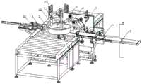
FIG. 1 is a schematic structural diagram according to a first embodiment of the present invention;
FIG. 2 is a schematic view of a portion of the structure of FIG. 1;
FIG. 3 is an enlarged view of portion A of FIG. 2;
FIG. 4 is an enlarged view of portion B of FIG. 2;
fig. 5 is a schematic structural view of a labeling mechanism according to an embodiment of the present invention;
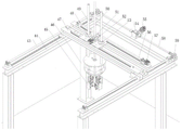
FIG. 6 is a schematic structural view of a hoisting mechanism in the first embodiment of the present invention;
FIG. 7 is a schematic view of a part of a hoisting mechanism according to a first embodiment of the present invention;
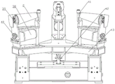
FIG. 8 is a schematic view of the clamping assembly of FIG. 1;
fig. 9 is a schematic structural diagram of a supporting mechanism according to a second embodiment of the invention.
Detailed Description
The following is further detailed by way of specific embodiments:
reference numerals in the drawings of the specification include: the automatic labeling machine comprises a conveying roller way 1, a supporting roller 2, a workpiece 3, a fixing rod 4, a rotating wheel 5, a rotating disc 6, a belt roller 7, a screw rod 8, a mounting frame 9, a connecting rod 10, a driving wheel 11, a limiting plate 12, a conveying double-roller 13, a conveying cylinder 14, an inserting rod 15, an opening and closing cylinder 16, a conveying clamp 17, a clamping cylinder 18, a movable cutter 19, a limiting table 20, a labeling mechanism 21, a centering roller 22, a centering cylinder 23, a pressing roller 24, a cutter 25, a fixing roller 26, a cutting cylinder 27, a pressing cylinder 28, a mounting plate 29, a labeling cylinder 30, a limiting roller 31, a bulge 32, a fixing plate 33, a fixing seat 34, a guide roller 35, a label roller 36, a bracket 37, a rotating motor 38, a driven wheel 39, a driving wheel 40, a positioning roller 41, a lifting cylinder 42, a first screw rod 43, a cross beam 44, a clamping assembly 45, an upright column 46, a, The device comprises a sliding plate 53, a first bevel gear set 54, a driving motor 55, a second screw rod 56, a sliding motor 57, a rotating shaft 58, a second bevel gear set 59, a connecting plate 60, a connecting seat 61, a second connecting rod 62, a first connecting rod 63, a vertical plate 64, a hanging bracket 65, a guide block 66 and a clamping jaw 67.
Example one
As shown in fig. 1 and 2, the copper coil pipe packing machine comprises a supporting mechanism for supporting a workpiece 3 and driving the workpiece 3 to rotate, a conveying mechanism for conveying the workpiece 3 to the supporting mechanism, a hoisting mechanism for hoisting the workpiece 3, a packing mechanism for winding a packing tape around the workpiece 3, and a labeling mechanism 21 for labeling the workpiece 3, wherein the supporting mechanism is installed on the conveying mechanism, and the labeling mechanism 21 is installed on one side of the conveying mechanism.
Conveying mechanism adopts rollgang 1, and supporting mechanism includes three backing roll 2 that transversely set up, and it has the breach that is used for holding backing roll 2 to open on the rollgang 1. The three supporting rollers 2 are all in a conical column shape, the three supporting rollers 2 enclose into an annular shape, the small-diameter ends of the three supporting rollers 2 face the circle center of the annular shape, and the intervals between the three supporting rollers 2 are the same. The three supporting rollers 2 are connected with a rotating motor (not shown in the drawing of the embodiment), and the supporting rollers 2 are further connected with a lifting cylinder for driving the lifting cylinders to lift.
As shown in figure 1, a vertical plate is installed on the right side of the conveying roller way 1, a centering frame is installed at the top of the left side of the vertical plate, three vertical rods are installed on the centering frame, a centering roller 22 is sleeved on each three vertical rod in a rotating mode, and a centering cylinder 23 used for driving the three centering roller 22 to ascend and descend is connected to the top of each three centering roller. The three centering rollers 22 are insertable into the loop of the workpiece 3, and the roller surfaces of the three centering rollers 22 are each contactable with the inner wall of the workpiece 3. Three positioning rollers (not shown in the drawing of the embodiment) for connecting with the centering roller 22 are vertically arranged on the conveying roller way, and the centering roller 22 can be inserted onto the positioning rollers after descending.
As shown in fig. 2, the wrapping mechanism includes a fixing lever 4 for fixing the wrapping band, a C-shaped turn table 6, a feeding assembly for holding the wrapping band and feeding the wrapping band to the turn table 6, and a cutting assembly for cutting the wrapping band. The rotary table 6 is connected with a driving component for driving the rotary table to rotate, the driving component comprises a driving wheel 11, the driving wheel 11 is rotatably arranged at the outer edge of the rotary table 6 and forms a friction rotating pair with the rotary table 6, a driving motor (not shown in the figure) is arranged behind the driving wheel 11, and a belt is tensioned between the driving motor and the driving wheel 11. A plurality of belt rollers 7 are vertically arranged on the surface of the rotary table 6 through bolts, the belt rollers 7 are uniformly distributed on the rotary table 6, a plurality of rotating wheels 5 are rotatably arranged on the outer edge of the rotary table 6, the rotating wheels 5 are uniformly distributed on the periphery of the rotary table 6, and each rotating wheel 5 and the rotary table 6 form a friction rotating pair.
The packaging mechanism further comprises a pressing belt (not shown in the figure) for pressing the packaging belt, a mounting frame 9 is installed on the right side of the rotary table 6, two vertical screw rods 8 are connected to the mounting frame 9 in a threaded mode, a connecting rod 10 is connected between the bottom ends of the two screw rods 8, and guide roller pairs are installed below the connecting rod 10. The left end of the compression belt is fixedly sleeved on the fixed rod 4, and the right end of the compression belt penetrates through the guide pair roller and then is fixedly sleeved on the connecting rod 10, so that the compression belt is tensioned on the belt roller 7 positioned on the upper half part of the rotary table 6. The height of the right end of the compression belt can be adjusted by rotating the screw rod 8, so that the tightness of the compression belt can be adjusted.
As can be seen from fig. 2, 3 and 4, the conveying assembly includes a conveying pair roller 13, a limiting table 20 is installed between the conveying pair roller 13 and the rotating disc 6, a limiting plate 12 is hinged on the limiting table 20, a channel for the packaging tape to pass through is formed between the limiting plate 12 and the limiting table 20, and the free end of the limiting plate 12 contacts with the top of the limiting table 20. The conveying clamp 17 for clamping the packaging belt is installed on one side of the limiting table 20, the conveying clamp 17 is connected with a clamping cylinder 18 and an opening and closing cylinder 16 for driving the clamping cylinder to open and close, the clamping cylinder 18 is used for driving the conveying clamp 17 to be close to or far away from the packaging belt, the clamping cylinder 18 is connected with a conveying cylinder 14 perpendicular to the clamping cylinder 18, and the conveying cylinder 14 is used for driving the conveying clamp 17 to be close to or far away from the conveying roller way 1.
A shearing mechanism for shearing the packaging tape is arranged between the limiting table 20 and the rotary table 6, the shearing mechanism comprises a fixed cutter (not shown in the figure) and a movable cutter 19 which is used for shearing (with scissors) the packaging tape in a matching way with the fixed cutter, the movable cutter 19 is arranged below the fixed cutter, and the movable cutter 19 is connected with a shearing cylinder (not shown in the figure) for driving the movable cutter to lift.
As shown in fig. 5, a support 37 is transversely installed on the right side of the roller conveyor 1 through a bolt, an installation plate 29 is slidably installed on the support 37, a labeling cylinder 30 is installed on the support 37, and a piston rod of the labeling cylinder 30 is connected with the installation plate 29. Install vertical label roller 36 through the bolt rotation on the mounting panel 29, install vertical guide roll 35 through the bolt rotation on the left side of label roller 36, fixing base 34 is installed through the bolt in guide roll 35 left side, and fixing base 34 inclines to set up. One side of the fixing seat 34 close to the conveying roller way 1 is fixed with a fixing plate 33 through a bolt, a channel for a label to pass through is formed between the fixing plate 33 and the fixing seat 34, one side of the fixing seat 34 close to the conveying roller way 1 is rotatably provided with a vertical fixing roller 26, and one end of the fixing plate 33 close to the conveying roller way 1 is tangent to the roller surface of the fixing roller 26. The fixing seat 34 outwards protrudes towards the middle of one side of the conveying roller way 1 to form a strip-shaped protrusion 32, the protrusion 32 is arranged along the length direction of the fixing seat 34, an annular protrusion 32 is formed on the roller surface of the fixing roller 26, and the two protrusions 32 are on the same horizontal line. An avoiding hole for avoiding the protrusion 32 on the fixed roller 26 is formed at one end of the fixed plate 33 tangent to the fixed roller 26, and the protrusion 32 on the fixed roller 26 protrudes from the avoiding hole.
The cutter 25 is installed on the left side of the fixed roller 26, the cutter 25 is connected with a cutting cylinder 27 which drives the cutter 25 to move towards the conveying roller way 1, a vertical limiting roller 31 is installed between the cutter 25 and the fixed roller 26 in a rotating mode through a bolt, and the roller surface of the limiting roller 31 can be abutted against the outer wall of the workpiece 3. The side of the cutting knife 25 far away from the limiting roller 31 is rotatably provided with a vertical pressing roller 24, the pressing roller 24 can be tightly propped against the outer wall of the workpiece 3, the pressing roller 24 is connected with a pressing cylinder 28, and the pressing cylinder 28 is arranged on a support 37.
As shown in fig. 6, 7 and 8, the hoisting mechanism comprises a mounting frame 9, the mounting frame 9 comprises two beams 44 arranged in parallel, the right ends of the two beams 44 are connected, and the bottoms of the two ends of the two beams 44 are respectively fixed with an upright column 46 through bolts. All rotate on two crossbeams 44 and install first lead screw 43, two first lead screws 43 all set up along crossbeam 44's axial, all rotate on two first lead screws 43 and are connected with first nut, are connected with carriage 47 between two crossbeams 44, and carriage 47's both ends rotate with two first nuts respectively and are connected.
The mounting bracket 9 is provided with a driving mechanism for driving the two first lead screws 43 to rotate, the driving mechanism includes a driving motor 55, the driving motor 55 is connected with a first bevel gear set 54, the first bevel gear set 54 includes a first driving bevel gear and two first driven bevel gears (not shown in the figure), the two first driven bevel gears are engaged with two sides of the first driving bevel gear, and the first driving bevel gear is in key connection with an output shaft of the driving motor 55. Two rotating shafts 58 are installed on two sides of the driving motor 55, and two first driven bevel gear keys are connected on the two rotating shafts 58. The outer ends of the two rotating shafts 58 are connected with the two first screw rods 43 through a second bevel gear set 59, the second bevel gear set 59 comprises a second driving bevel gear and a second driven bevel gear, the second driving bevel gear is connected to the rotating shafts 58 in a key mode, and the second driven bevel gear is connected to the first screw rods 43 in a key mode.
The sliding plate 53 is slidably mounted on the sliding frame 47, the second lead screw 56 is rotatably mounted on the sliding frame 47, the right end of the second lead screw 56 is connected with the sliding motor 57, the second lead screw 56 is arranged along the length direction of the sliding frame 47, the second nut is rotatably connected on the second lead screw 56, and the second nut is rotatably connected with the sliding plate 53.
The sliding plate 53 is connected with a vertical guide rod 49 in a sliding mode, the guide rod 49 penetrates through the sliding plate 53, the sliding plate 53 is connected with a vertical threaded rod 50 in a sliding mode, the threaded rod 50 penetrates through the sliding plate 53, a worm wheel 51 is connected to the threaded rod 50 in a threaded mode, the worm wheel 51 is rotatably installed on the sliding plate 53, the right side of the worm wheel 51 is meshed with a worm 52, the worm 52 is connected with a lifting motor 48, and the lifting motor 48 is installed on the sliding plate.
The clamping assembly 45 comprises a vertically arranged hanging bracket 65, a connecting disc 60 is connected to the upper side of the hanging bracket 65 through a bolt, the bottom end of the hanging bracket 65 is fixedly connected with the connecting disc 60, and the bottom end of the threaded rod 50 is rotatably connected to the connecting disc 60. The hanger 65 is slidably mounted with a connecting seat 61, a cylinder (not shown) is mounted below the connecting seat 61, and a piston rod of the cylinder is fixedly connected with the bottom of the connecting seat 61.
Four clamping jaws 67 are installed to gallows 65 periphery, and four clamping jaws 67 equipartitions are around gallows 65. A vertical plate 64 is installed on the inner side of each clamping jaw 67, the bottom end of the vertical plate 64 is hinged to the bottom of the clamping jaw 67, a first connecting rod 63 is hinged between the top and the middle of the vertical plate 64 and the hanger 65, a second connecting rod 62 is hinged between the vertical plate 64 and the connecting seat 61, and the hinge points of the first connecting rod 63 and the second connecting rod 62 on the top are the same as those of the vertical plate 64. Guide blocks 66 are mounted on two sides of each vertical plate 64, and the guide blocks 66 are connected to the clamping jaws 67 through bolts.
The specific implementation process is as follows:
according to the position of the workpiece 3, the driving motor 55 is started, the driving motor 55 drives the two first screw rods 43 to rotate through the first bevel gear set 54, the rotating shaft 58 and the second bevel gear set 59, and the two first screw rods 43 drive the two first nuts to rotate, so that the carriage 47 is driven to move along the cross beam 44. Meanwhile, the sliding motor 57 is started to drive the second lead screw 56 to rotate, the second lead screw 56 drives the second nut to rotate, and the sliding plate 53 is driven by the second nut to slide on the sliding frame 47. The gripping assembly 45 is moved over the workpiece 3 by adjusting the position of the carriage 47 and the position of the gripping assembly 45 on the carriage 47.
After the clamping component 45 reaches the upper part of the workpiece 3, the lifting motor 48 is started, the lifting motor 48 drives the worm wheel 51 to rotate through the worm 52, and the worm wheel 51 drives the screw rod 8 to rotate, so that the clamping component 45 is driven to move downwards, and the four clamping jaws 67 extend into the workpiece 3. At the moment, the piston rod of the air cylinder extends out, the connecting seat 61 is jacked up, the first connecting rod 63 and the second connecting rod 62 are separated, and the four clamping jaws 67 are folded, so that the workpiece 3 can be conveniently placed in.
After the four clamping jaws 67 are placed in the workpiece 3, the piston rod of the cylinder is retracted, the connecting seat 61 moves downwards, the first connecting rod 63 and the second connecting rod 62 are closed, the clamping jaws 67 are pushed outwards, the four clamping jaws 67 are separated, and the four clamping jaws 67 are tightly pressed on the inner wall of the workpiece 3, so that the workpiece 3 is clamped. After clamping, the workpiece 3 can be lifted through the reverse rotation of the lifting motor 48, and after lifting, the workpiece 3 is transported to the conveying roller way 1 through the driving sliding plate 53 and the sliding frame 47, so that the feeding of the workpiece 3 is realized.
The work piece 3 is conveyed to the three supporting rollers 2 by the conveying roller way 1, and at the moment, the three supporting rollers 2 are positioned below the roller surface of the conveying roller way 1, so that the conveying of the work piece 3 is not influenced. The lifting cylinder drives the three supporting rollers 2 to ascend and lift the workpiece 3. The centering cylinder 23 drives the three centering rollers 22 to move down, and the three centering rollers 22 are connected with the positioning rollers, thereby centering the workpiece 3.
The packaging tape is wound and sleeved on the inserting rod 15, the end part of the packaging tape is pulled out, the end part of the packaging tape sequentially passes through a channel formed between the conveying double rollers 13 and between the limiting plate 12 and the limiting table 20 and between the movable cutter 19 and the fixed cutter (at the moment, the movable cutter 19 is separated from the fixed cutter, and the packaging tape is not contacted with the fixed cutter), reaches the driving wheel 11, the conveying clamp 17 is driven to move to the driving wheel 11 by utilizing the conveying cylinder 14, the opening and closing cylinder 16 is started to drive the conveying clamp 17 to be opened, meanwhile, the clamping cylinder 18 drives the conveying clamp 17 to be close to the driving wheel 11, and the opening and closing cylinder 16 drives the conveying clamp 17 to be closed to. The clamp rear feed cylinder 14 drives the feed clamp 17 to the left to the position shown in fig. 2, where the wrapping band is stretched over the band roller 7 in the lower part of the turntable 6.
The driving motor is started to drive the driving wheel 11 to rotate clockwise through the driving belt, so as to drive the rotary table 6 to rotate anticlockwise, the belt roller 7 at the lower part of the rotary table 6 rotates upwards to hook the packaging belt from the bottom and drive the packaging belt to rotate anticlockwise, the upper half part of the rotary table 6 is inserted into the ring of the workpiece 3 and then rotates to the upper part of the workpiece 3, and therefore the packaging belt is wound on the workpiece 3. The belt is loosened after being wound for two circles, the rotary table 6 continues to rotate, meanwhile, the three supporting rollers 2 rotate towards one direction, the workpiece 3 is driven to rotate anticlockwise, the whole workpiece 3 can be wound with the packaging belt gradually, and the packaging of the workpiece 3 is achieved. During the rotation of the workpiece 3, the centering rollers 22 can contact the inner wall of the workpiece 3, thereby guiding and centering the workpiece 3 and preventing the workpiece 3 from shifting during the rotation.
The label roll is sleeved on the label roller 36, the label roll is fixed, the end part of the label is pulled out, the label passes through a channel formed between the fixed plate 33 and the fixed seat 34 in a state that the adhering surface faces to the conveying roller way 1, and is pulled to the pressing roller 24, and the label is tensioned on the guide roller 35 and the limiting roller 31. Since the fixed plate 33 is tangent to the fixed roller 26 and the fixed seat 34 are provided with the projections 32, the label can be clamped between the fixed plate 33 and the fixed roller 26.
When the part of the workpiece 3 wound with the packaging tape rotates to the labeling mechanism 21, the labeling cylinder 30 is started to push the mounting plate 29 leftwards, so that the fixed roller 26 is abutted against the outer wall of the workpiece 3, the end part of the label is contacted with the outer wall of the workpiece 3 at the moment, the pressing cylinder 28 is started to push the pressing roller 24 to move leftwards, and the pressing roller 24 presses the end part of the label on the outer wall of the workpiece 3. Along with the rotation of work piece 3, the label pastes on the outer wall of work piece 3 gradually, realizes the subsides mark of work piece 3.
After one circle of label is pasted, the labeling cylinder 30 drives the mounting plate 29 to retract, the limiting roller 31 is separated from the workpiece 3, the pressing roller 24 is still pressed on the workpiece 3, and a section of label is torn between the pressing roller 24 and the limiting roller 31 at the moment, so that the label is convenient to cut; the cutting cylinder 27 drives the cutting knife 25 to move leftwards, the label is cut off between the pressing roller 24 and the limiting roller 31, the workpiece 3 continues to rotate, and the tail of the label is pressed on the workpiece 3 by the pressing roller 24. And then the supporting roller 2 is lowered, the workpiece 3 is placed on the conveying roller way 1, the conveying roller way 1 is started to convey the workpiece 3 away, and then the workpiece 3 is hoisted from the conveying roller way 1 by using a hoisting mechanism, so that the workpiece 3 is discharged. The next workpiece 3 is conveyed to the support rollers 2 and so on, and the packing of all the workpieces 3 is realized. During actual application, automatic stacking and group stacking of workpieces can be realized through the hoisting mechanism, labor force is saved, and machining efficiency is improved.
Example two
As shown in fig. 9, the difference between the first embodiment and the second embodiment is that a support frame is installed below the rollgang 1, three support rollers 2 are all installed on the support frame, a lifting cylinder 42 is installed below the support frame, and a piston rod of the lifting cylinder 42 is connected with the bottom of the support frame. Three rotating electrical machines 38 are installed on the supporting frame, the three rotating electrical machines 38 are respectively located below the three supporting rolls 2, and transmission assemblies are connected between the three rotating electrical machines 38 and the three supporting rolls 2. In this embodiment, the transmission assembly includes a driving wheel 40 and a driven wheel 39, a transmission belt (not shown in the figure) is tensioned on the driving wheel 40 and the driven wheel 39, the driving wheel 40 is connected with an output shaft key of the rotating motor 38, and the driven wheel 39 is coaxially connected with the large diameter end of the supporting roller 2. In this embodiment, the driving pulley 40 and the driven pulley 39 both use sprockets, and the transmission belt uses a chain.
Compare and directly be connected rotating electrical machines 38 and backing roll 2, the inside space of rollgang 1 has rationally been utilized to this embodiment, has reduced the area of whole device.
The foregoing is merely an example of the present invention and common general knowledge of known specific structures and features of the embodiments is not described herein in any greater detail. It should be noted that, for those skilled in the art, without departing from the structure of the present invention, several changes and modifications can be made, which should also be regarded as the protection scope of the present invention, and these will not affect the effect of the implementation of the present invention and the practicability of the patent. The scope of the claims of the present application shall be determined by the contents of the claims, and the description of the embodiments and the like in the specification shall be used to explain the contents of the claims.
Claims (10)
1. Copper coil pipe packagine machine, its characterized in that: the labeling machine comprises a supporting mechanism for supporting a workpiece and driving the workpiece to rotate, a conveying mechanism for conveying the workpiece to the supporting mechanism, a hoisting mechanism for hoisting the workpiece, a packaging mechanism for winding a packaging tape on the workpiece and a labeling mechanism for labeling the workpiece, wherein the supporting mechanism is arranged on the conveying mechanism, and the labeling mechanism is arranged on one side of the conveying mechanism.
2. The copper coil packaging machine of claim 1, wherein: the supporting mechanism comprises a plurality of transversely arranged supporting rollers, the supporting rollers are connected with a rotating motor, the supporting rollers are further connected with a lifting cylinder for driving the supporting rollers to lift, the supporting rollers are surrounded into an annular shape, the supporting rollers are conical, and the small-diameter ends of the supporting rollers face the center of the annular circle.
3. The copper coil packaging machine of claim 2, wherein: at least two centering rollers are arranged above the supporting mechanism, the centering rollers are connected with a centering cylinder used for driving the centering cylinder to lift, a positioning roller used for being connected with the centering rollers is arranged on the conveying mechanism, the centering rollers are vertically arranged, and the roller surfaces of the centering rollers can be in contact with the inner wall of the workpiece.
4. The copper coil packaging machine of claim 3, wherein: the labeling mechanism is arranged in a sliding manner and can be close to or far away from the workpiece; the labeller constructs including the fixed subassembly that is used for fixed label free end, the cutter that is used for cutting the label, be used for compressing tightly the compression roller on the work piece outer wall with the label roller that is used for fixed label, fixed subassembly sets up the one side that is close to supporting mechanism at the label roller, and the compression roller setting is in the one side that fixed subassembly is close to supporting mechanism, and the compression roller rotates the setting, and the cutter slides and sets up between fixed subassembly and compression roller, and the cutter is connected with the cutting cylinder.
5. The copper coil packaging machine of claim 4, wherein: the fixed subassembly includes the fixing base, and the one end that the label roller was kept away from to the fixing base is rotated and is provided with the fixed roll, and the fixing base side is provided with the fixed plate, and the one end of fixed plate is tangent with the roll surface of fixed roll, forms the passageway that supplies the label to pass between fixed plate and the fixing base, and the width of passageway reduces from the one end that the fixing base is close to the label roller to the other end gradually.
6. The copper coil packaging machine of claim 5, wherein: one side that the fixing base was equipped with the fixed plate is provided with the arch, and the arch sets up along the direction of transfer of label, also is provided with the arch on the fixed roll surface, and the fixed plate is seted up towards the one end of fixed roll and is dodged the bellied hole of dodging on the fixed roll.
7. The copper coil packaging machine of claim 1, wherein: the packaging mechanism comprises a C-shaped rotary table, a conveying assembly and a shearing assembly, wherein the conveying assembly is used for clamping a packaging belt and conveying the packaging belt to the rotary table, the shearing assembly is used for shearing the packaging belt, the rotary table is connected with a driving assembly used for driving the rotary table to rotate, and a plurality of belt rollers are vertically arranged on the disc surface of the rotary table.
8. The copper coil packaging machine of claim 7, wherein: the packaging mechanism further comprises a pressing belt used for pressing the packaging belt, two ends of the pressing belt are fixed on two sides of the rotary table, the pressing belt is tensioned on a belt roller located on the upper half portion of the rotary table, and the tightness of the pressing belt is adjustable.
9. The copper coil packaging machine of claim 8, wherein: the conveying assembly comprises a conveying pair roller, a limiting table is arranged between the conveying pair roller and the rotary table, a limiting plate is hinged to the limiting table, a channel for the packaging tape to pass through is formed between the limiting plate and the limiting table, and the free end of the limiting plate is in contact with the top of the limiting table; spacing platform one side is provided with the transport clamp that is used for the centre gripping strap, carries to press from both sides and is connected with the centre gripping cylinder and is used for driving its cylinder that opens and shuts, and the centre gripping cylinder is used for driving to carry to press from both sides and is close to or keeps away from the strap, and the centre gripping cylinder is connected with rather than the vertically transport cylinder, carries the cylinder to be used for driving to carry to press from both sides and is close.
10. The copper coil packaging machine of claim 1, wherein: the hoisting mechanism comprises a mounting frame, a sliding frame is slidably mounted at the top of the mounting frame, a clamping assembly used for hoisting a workpiece is slidably mounted on the sliding frame, the sliding direction of the clamping assembly is perpendicular to that of the sliding frame, and the clamping assembly is connected with a lifting assembly used for driving the lifting assembly to lift.
Priority Applications (1)
| Application Number | Priority Date | Filing Date | Title |
|---|---|---|---|
| CN202011593173.0A CN112644757B (en) | 2020-12-29 | 2020-12-29 | Copper coil pipe packing machine |
Applications Claiming Priority (1)
| Application Number | Priority Date | Filing Date | Title |
|---|---|---|---|
| CN202011593173.0A CN112644757B (en) | 2020-12-29 | 2020-12-29 | Copper coil pipe packing machine |
Publications (2)
| Publication Number | Publication Date |
|---|---|
| CN112644757A true CN112644757A (en) | 2021-04-13 |
| CN112644757B CN112644757B (en) | 2022-08-05 |
Family
ID=75363749
Family Applications (1)
| Application Number | Title | Priority Date | Filing Date |
|---|---|---|---|
| CN202011593173.0A Active CN112644757B (en) | 2020-12-29 | 2020-12-29 | Copper coil pipe packing machine |
Country Status (1)
| Country | Link |
|---|---|
| CN (1) | CN112644757B (en) |
Cited By (2)
| Publication number | Priority date | Publication date | Assignee | Title |
|---|---|---|---|---|
| CN116119076A (en) * | 2023-04-19 | 2023-05-16 | 常州市行佳高科硬质合金有限公司 | Packaging production line for tungsten-titanium alloy and working method thereof |
| CN117048913A (en) * | 2023-10-12 | 2023-11-14 | 潍坊顺福昌橡塑有限公司 | Tire packaging control system |
Citations (5)
| Publication number | Priority date | Publication date | Assignee | Title |
|---|---|---|---|---|
| JPH11342910A (en) * | 1998-06-01 | 1999-12-14 | Fuji Photo Film Co Ltd | Method and device for packaging cylindrical article |
| CN106628436A (en) * | 2016-11-14 | 2017-05-10 | 江苏新永良线缆机械有限公司 | Full-automatic cable disc forming and belting machine |
| CN108394594A (en) * | 2018-05-04 | 2018-08-14 | 上海阑途信息技术有限公司 | A kind of tire baling press and assembly line |
| CN109878835A (en) * | 2019-03-28 | 2019-06-14 | 东莞万旗机械设备有限公司 | The automation equipment of wire rod packaging |
| CN109878791A (en) * | 2019-03-28 | 2019-06-14 | 东莞万旗机械设备有限公司 | Wire rod packing device |
-
2020
- 2020-12-29 CN CN202011593173.0A patent/CN112644757B/en active Active
Patent Citations (5)
| Publication number | Priority date | Publication date | Assignee | Title |
|---|---|---|---|---|
| JPH11342910A (en) * | 1998-06-01 | 1999-12-14 | Fuji Photo Film Co Ltd | Method and device for packaging cylindrical article |
| CN106628436A (en) * | 2016-11-14 | 2017-05-10 | 江苏新永良线缆机械有限公司 | Full-automatic cable disc forming and belting machine |
| CN108394594A (en) * | 2018-05-04 | 2018-08-14 | 上海阑途信息技术有限公司 | A kind of tire baling press and assembly line |
| CN109878835A (en) * | 2019-03-28 | 2019-06-14 | 东莞万旗机械设备有限公司 | The automation equipment of wire rod packaging |
| CN109878791A (en) * | 2019-03-28 | 2019-06-14 | 东莞万旗机械设备有限公司 | Wire rod packing device |
Cited By (3)
| Publication number | Priority date | Publication date | Assignee | Title |
|---|---|---|---|---|
| CN116119076A (en) * | 2023-04-19 | 2023-05-16 | 常州市行佳高科硬质合金有限公司 | Packaging production line for tungsten-titanium alloy and working method thereof |
| CN116119076B (en) * | 2023-04-19 | 2023-06-23 | 常州市行佳高科硬质合金有限公司 | Packaging production line for tungsten-titanium alloy and working method thereof |
| CN117048913A (en) * | 2023-10-12 | 2023-11-14 | 潍坊顺福昌橡塑有限公司 | Tire packaging control system |
Also Published As
| Publication number | Publication date |
|---|---|
| CN112644757B (en) | 2022-08-05 |
Similar Documents
| Publication | Publication Date | Title |
|---|---|---|
| CN112644757B (en) | Copper coil pipe packing machine | |
| CN211001995U (en) | Winding and packing device | |
| US4461136A (en) | Method and apparatus for enveloping a plurality of items in a stretchable film | |
| CN113200164B (en) | Full-automatic cylinder packaging cover placing, positioning and sealing device | |
| CN111498483B (en) | Automatic conveying and stacking equipment for rice in packaging bags | |
| CN112357186A (en) | Automatic packaging production equipment for outer film of packaging box and production process thereof | |
| CN112429295A (en) | Automatic adhesive tape packaging method for FOSB (oriented strand bundle) assembly line | |
| CN218617456U (en) | Carton packing machine | |
| CN110902577B (en) | Plate arranging device for placing bagged fertilizer | |
| CN104290977B (en) | Labeling device and automatic labeling machine | |
| CN216540574U (en) | Pull ring punching machine feeding device for manufacturing pop can cover | |
| CN115971559A (en) | Pipe fitting cutting device | |
| CN215972257U (en) | Tire clamping device for tire packaging | |
| CN214356865U (en) | Automatic adhesive tape wrapping device for wafer packaging box assembly line | |
| CN211594622U (en) | Automatic packaging production line for stainless steel mesh | |
| CN212174042U (en) | Paper packaging production line | |
| CN108454929B (en) | Material roll packing device of strip mill | |
| CN113772147A (en) | Tire packing method | |
| CN112455759A (en) | Automatic adhesive tape wrapping device for wafer packaging box assembly line | |
| CN220199731U (en) | Film roll packaging machine | |
| CN218806811U (en) | E-commerce goods pre-packaging equipment | |
| CN220315444U (en) | Intelligent integrated packaging system | |
| CN215972255U (en) | Tire rotating device for tire packaging | |
| CN220350785U (en) | Auxiliary device for protective frame of washing machine | |
| CN216762255U (en) | LCD display glass cover plate binding machine |
Legal Events
| Date | Code | Title | Description |
|---|---|---|---|
| PB01 | Publication | ||
| PB01 | Publication | ||
| SE01 | Entry into force of request for substantive examination | ||
| SE01 | Entry into force of request for substantive examination | ||
| GR01 | Patent grant | ||
| GR01 | Patent grant |