CN111937649A - Zigzag film greenhouse for overwintering production in Yangtze river basin area - Google Patents
Zigzag film greenhouse for overwintering production in Yangtze river basin area Download PDFInfo
- Publication number
- CN111937649A CN111937649A CN202010881757.1A CN202010881757A CN111937649A CN 111937649 A CN111937649 A CN 111937649A CN 202010881757 A CN202010881757 A CN 202010881757A CN 111937649 A CN111937649 A CN 111937649A
- Authority
- CN
- China
- Prior art keywords
- greenhouse
- arch
- ventilation
- heat preservation
- north
- Prior art date
- Legal status (The legal status is an assumption and is not a legal conclusion. Google has not performed a legal analysis and makes no representation as to the accuracy of the status listed.)
- Pending
Links
Images


Classifications
-
- A—HUMAN NECESSITIES
- A01—AGRICULTURE; FORESTRY; ANIMAL HUSBANDRY; HUNTING; TRAPPING; FISHING
- A01G—HORTICULTURE; CULTIVATION OF VEGETABLES, FLOWERS, RICE, FRUIT, VINES, HOPS OR SEAWEED; FORESTRY; WATERING
- A01G9/00—Cultivation in receptacles, forcing-frames or greenhouses; Edging for beds, lawn or the like
- A01G9/14—Greenhouses
- A01G9/16—Dismountable or portable greenhouses ; Greenhouses with sliding roofs
-
- A—HUMAN NECESSITIES
- A01—AGRICULTURE; FORESTRY; ANIMAL HUSBANDRY; HUNTING; TRAPPING; FISHING
- A01G—HORTICULTURE; CULTIVATION OF VEGETABLES, FLOWERS, RICE, FRUIT, VINES, HOPS OR SEAWEED; FORESTRY; WATERING
- A01G9/00—Cultivation in receptacles, forcing-frames or greenhouses; Edging for beds, lawn or the like
- A01G9/22—Shades or blinds for greenhouses, or the like
- A01G9/227—Shades or blinds for greenhouses, or the like rolled up during non-use
-
- A—HUMAN NECESSITIES
- A01—AGRICULTURE; FORESTRY; ANIMAL HUSBANDRY; HUNTING; TRAPPING; FISHING
- A01G—HORTICULTURE; CULTIVATION OF VEGETABLES, FLOWERS, RICE, FRUIT, VINES, HOPS OR SEAWEED; FORESTRY; WATERING
- A01G9/00—Cultivation in receptacles, forcing-frames or greenhouses; Edging for beds, lawn or the like
- A01G9/24—Devices or systems for heating, ventilating, regulating temperature, illuminating, or watering, in greenhouses, forcing-frames, or the like
- A01G9/241—Arrangement of opening or closing systems for windows and ventilation panels
-
- Y—GENERAL TAGGING OF NEW TECHNOLOGICAL DEVELOPMENTS; GENERAL TAGGING OF CROSS-SECTIONAL TECHNOLOGIES SPANNING OVER SEVERAL SECTIONS OF THE IPC; TECHNICAL SUBJECTS COVERED BY FORMER USPC CROSS-REFERENCE ART COLLECTIONS [XRACs] AND DIGESTS
- Y02—TECHNOLOGIES OR APPLICATIONS FOR MITIGATION OR ADAPTATION AGAINST CLIMATE CHANGE
- Y02A—TECHNOLOGIES FOR ADAPTATION TO CLIMATE CHANGE
- Y02A40/00—Adaptation technologies in agriculture, forestry, livestock or agroalimentary production
- Y02A40/10—Adaptation technologies in agriculture, forestry, livestock or agroalimentary production in agriculture
- Y02A40/25—Greenhouse technology, e.g. cooling systems therefor
Landscapes
- Life Sciences & Earth Sciences (AREA)
- Environmental Sciences (AREA)
- Greenhouses (AREA)
Abstract
The invention discloses a zigzag film greenhouse for overwintering production in Yangtze river basin areas, which comprises a greenhouse framework, a ventilation system, a curtain system and a heat preservation system, wherein the greenhouse framework is provided with a plurality of heating plates; the greenhouse framework comprises a main upright post, an inner upright post and a greenhouse arch frame which is supported by the main upright post and the inner upright post together; the main upright columns on the east and west sides are connected at the shoulders of the greenhouse through cross braces, and the main upright columns on the north and south sides are connected at the shoulders of the greenhouse through cross section crosspieces; the greenhouse arch frame comprises a main arch and an auxiliary arch, and the main arch and the auxiliary arch are connected in a north-south manner through arch bar pull rods; the ventilation system comprises a bottom ventilation opening, a side ventilation opening and a top ventilation opening, the top ventilation opening is provided with a ventilation window of the rail type windowing system, and the natural ventilation of the greenhouse can be utilized to obtain a good cooling effect in summer high temperature of the Yangtze river basin. The plastic film greenhouse is also provided with an inner sun-shading heat-preservation curtain system, an outer sun-shading system and a heat-preservation quilt system, can realize heat preservation in winter and temperature reduction in summer, and can also be used for overwintering cultivation.
Description
Technical Field
The invention relates to a greenhouse, in particular to a zigzag film greenhouse for overwintering production in Yangtze river basin areas over summer.
Background
After 30 years of development of modern facility gardening in China, facility types, production modes and technical systems with different regional characteristics are basically formed. In facility cultivation types in China, the sunlight greenhouse is widely applied to northern areas in China, energy consumption of vegetables in the northern areas in winter is greatly reduced, but the sunlight greenhouse is not suitable for being developed in the southern areas with little sunlight due to the limitation of conditions such as climate and the like. The novel multi-span plastic film greenhouse and the plastic greenhouse commonly used in the Yangtze river basin area at present have the advantages of simple structure, convenient construction and the like, but the structure is unstable, and the natural ventilation cooling capacity and the heat preservation capacity of the greenhouse are poor. The Yangtze river basin region mostly belongs to subtropical monsoon climate, high temperature and raininess in summer, cold and dry in winter, the highest temperature in summer can reach about 40 ℃, and the lowest temperature in winter can reach about minus 4 ℃. After the ventilation opening of the multi-span plastic film greenhouse top of the traditional dome-shaped roof is opened, the defects of easy water seepage in the greenhouse, easy film clamping, short service life and the like are overcome. The traditional greenhouse type in the place aims to achieve the purposes of cooling in summer and preserving heat in winter, mechanical cooling and heating equipment is used more, and the use cost and the energy consumption of the greenhouse are increased. The Yangtze river basin area is developed in economy, and the traffic is convenient, and agricultural products such as melon and fruit vegetables sell the way unobstructed, consequently, designs one kind and is applicable to the Yangtze river basin area, and low input high output, and the novel greenhouse that all can cultivate production in the four seasons, is the problem that awaits a urgent need to solve.
Disclosure of Invention
The invention aims to solve the technical problems of natural ventilation cooling and winter heat preservation by utilizing a greenhouse in summer aiming at the technical defects of a novel multi-span plastic film greenhouse and a plastic greenhouse used in the current Yangtze river basin area, and provides a zigzag film greenhouse for overwintering production over summer in the Yangtze river basin area, so that the input-output ratio is maximized, the daily use cost and the energy consumption of the greenhouse are reduced, and the requirements of agricultural mechanization are met better.
The purpose of the invention is realized by the following technical scheme:
a zigzag film greenhouse for overwintering production in Yangtze river basin areas comprises a greenhouse framework 51, a ventilation system 52, a curtain system 53 and a heat preservation system 54;
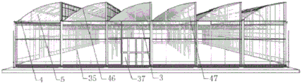
the greenhouse framework 51 comprises main upright posts 1 fixed by upright post foundations 39, and the main upright posts 1 of each span of the greenhouse are connected through trusses 3 in the greenhouse in the east-west direction; the main upright posts 1 on the east and west sides are connected in the south and north direction at the shoulder parts of the greenhouse through the cross braces 55, and the main upright posts 1 on the south and north sides are connected in the east and west direction at the shoulder parts of the greenhouse through the cross section crosspieces 32 so as to fix the whole greenhouse; an inner upright post 47 is arranged right above each truss 3 of the greenhouse and supports a greenhouse arch 46 together with the main upright post 1, and the main upright post 1 and the inner upright post 47 are connected in a north-south manner at the shoulder part of the greenhouse by a roof longitudinal beam 33; the greenhouse arch 46 is vertical to the ground to form the shoulder of the greenhouse, and comprises main arches 4 which are formed by arranging arch rods 86 between adjacent upright columns in the east-west direction to form the greenhouse, and auxiliary arches 5 which are formed by uniformly arranging 3 arch rods 86 between adjacent main arches 4 in the north-south direction at intervals of 1 meter; the span of the greenhouse is 8.00m, the total span is 3, the span is 24.00m, the span of each roof is 4.00m when each roof spans two roofs, the main arch 4 and the auxiliary arch 5 of each roof of the greenhouse are connected in the south-north direction through arch bar pull rods 19, and the roofs are connected through gutter 8 in the east-west direction; on the east and west sides of the greenhouse, the side auxiliary upright posts 6 are uniformly arranged between the adjacent main upright posts 1 at intervals of 1 meter, the top side auxiliary upright posts 7 are uniformly arranged between the east shoulder cross brace 55 and the ceiling longitudinal beam 33 of the greenhouse, the adjacent main upright posts 1 at intervals of 1 meter, the roof gutter 8 and the roof longitudinal beam 34, and the top side auxiliary upright posts 7 are uniformly arranged between the adjacent inner upright posts 47 at intervals of 1 meter; at the north and south sides of the greenhouse, greenhouse main arches at the north and south ends of a greenhouse arch frame 46 are supported by gable wind-resistant columns 35, and the gable wind-resistant columns 35 at the same side are connected east and west through cross-section crosspieces 32; diagonal rods are arranged between the main arches 4 and the main upright posts 1 on the east side of the greenhouse and between the main arches 4 and the inner upright posts 47 in the interior of the greenhouse to form main arch diagonal braces 20 of the greenhouse; arranging shear ribs 14 on east and west sides of arches between a second bay and a ninth bay of the greenhouse, and arranging the shear ribs 14 between adjacent spans in the greenhouse between the second bay and the ninth bay; sliding doors 37 are respectively installed on the west side and the south side of the greenhouse.
The ventilation system 52 includes bottom vents 57 around the greenhouse, side vents 58 at the side walls of the arch, and top vents 59 at the top of each roof. Bottom ventilation openings 57 are respectively arranged on the periphery of the lower portion of the greenhouse arch 46, three clamping grooves 62 are respectively arranged on the periphery of the greenhouse, the first clamping groove 621 is arranged above the dado 31 and is 20.00cm away from the ground, the distance between the clamping groove 622 and the clamping groove 621 is 45.00cm, the distance between the clamping groove 623 and the clamping groove 622 is 180.00cm, the windowing width is 180.00cm, and the windowing length is consistent with the length of one side of the greenhouse where the bottom ventilation openings 57 are located; each bottom vent 57 is provided with a set of electric film rolling and windowing system 41, the electric film rolling and windowing system 41 of the bottom vent comprises a film rolling machine 27, a film rolling rod 60, a film rolling pipe 61 and a handle 42, the stroke of the electric film rolling machine 27 is 190.00cm, the switch of the film rolling machine 27 is opened, the film rolling machine 27 can run on the film rolling rod 60 along with the film rolling pipe 61, and the opening and closing of the bottom vent can be controlled manually/electrically.
The side ventilation openings 58 are longitudinally arranged in the south-north direction and are six rows from east to west, the side ventilation openings 58 are opened at the position of 80.00cm at the upper end of the gutter 8, a clamping groove 624 is arranged in the south-north direction, the distance between the clamping groove 625 and the clamping groove 624 is 80.00cm, the windowing width is 80.00cm, the windowing length is consistent with the length of the greenhouse, each side ventilation opening is also provided with a set of electric film rolling windowing system 412, the stroke of the film rolling machine 272 is 90.00cm, and the opening and closing of the side ventilation openings 58 can be electrically controlled;
furthermore, top ventilation openings 59 are respectively arranged at the top ends of all roofs of the greenhouse, the top ventilation openings 59 adopt a rail type windowing system 16, the upper ends of ventilation windows 63 of the rail type windowing system are hinged to the top of the greenhouse arch frame, and the top ventilation openings 59 are covered when the roof is completely closed; the width of the single top ventilation opening 59 is 1.20m, the length is 39.00m, and the difference between the width and the end points of the greenhouse at the north and south is 0.50 m; the top ventilation opening 59 comprises a ventilation window frame 96, a plastic film 2 covered on the ventilation window frame 96), a white 30-mesh insect-proof net 23 covered on the inner side of the plastic film 24 and a rail type windowing system 16; the rail type windowing system 16 comprises a top windowing speed reducing motor 63, a connecting iron plate 97, a rotary longitudinal rod 98, a gear 99 and a gear type longitudinal rod 100, wherein the top end of the connecting iron plate 97 is fixed on the auxiliary arch 5 of the greenhouse, the lower part of the connecting iron plate 97 is provided with a mounting hole, the rotary longitudinal rod 98 penetrates through the mounting hole of the connecting iron plate 97 in the north-south direction and can rotate in the mounting hole, and the gears 99 are arranged on the rotary longitudinal rod 98 at equal intervals; the top end of the gear type vertical rod 100 is fixed with the ventilating window frame 96, the gear of the gear type vertical rod 100 is meshed with the gear 99, the rotating vertical rod 98 is driven by the window jacking speed reducing motor 63 to drive the gear type vertical rod 100 to move upwards to jack the ventilating window, and automatic ventilation at a fixed distance is realized.
The curtain system 53 comprises an inner sun-shading heat-preservation curtain system 65 and an outer sun-shading system 66; the inner sun-shading heat-preservation curtain system 65 comprises an inner sun-shading heat-preservation curtain 101, an inner sun-shading heat-preservation curtain motor 68, a gear type longitudinal rod 100, a coupler 69, a supporting roller 70, a longitudinal push rod 71, a rotary cross rod 72, a curtain supporting line 102 and a curtain pressing line 103, wherein the inner sun-shading heat-preservation curtain motor 68 is installed at the central position of the inner sun-shading heat-preservation curtain system 65 and is positioned below a truss 3 at the joint of a fifth bay and a sixth bay, the inner sun-shading heat-preservation curtain motor 68 drives the rotary cross rod 72 to drive the gear type longitudinal rod 100 and the longitudinal push rod 71 to move from north to south or from south to north through the coupler 69, and the inner sun-shading heat-preservation curtain; the electric control cabinet 67 of the greenhouse is provided with a switch of an inner sunshade heat preservation curtain motor 68, and the inner sunshade heat preservation curtain system 65 can be opened and closed under the instruction of an operator or a computer control system.
The outer sunshade system 53 comprises an outer sunshade framework system 73 and an outer sunshade control system 44, wherein the outer sunshade framework system 73 comprises outer sunshade columns 15, outer sunshade longitudinal beams 12 and outer sunshade transverse beams 13, one side of the lower ends of the outer sunshade columns 15 is rigidly connected with one side of a shed roof longitudinal beam 33 through a connecting piece through bolts, the outer sunshade transverse beams 13 are arranged in the east-west direction to enable the outer sunshade columns 15 to be connected in an east-west direction, and the outer sunshade longitudinal beams 12 are arranged in the north-south direction to enable the outer sunshade columns 15 to be connected in a north-south direction; the supporting rollers 702 are respectively arranged at the middle part and the lower parts of the two ends of the outer shading crossbeam 13, and the outer shading speed reducing motor 74 can also realize the electric control of the opening and closing of the outer shading net 25 through the shaft coupling 692, the gear type vertical rod 1002, the longitudinal push rod 712 and the rotating cross rod 722.
The heat preservation system 54 comprises a retractable heat preservation quilt 76 fixed at the top end of each roof of the greenhouse and a non-retractable side window heat preservation quilt 77 fixed at the side window of the greenhouse arch frame; the top end of the heat preservation quilt 76 is fixed in a heat preservation quilt connecting hole 78, and the winding and unwinding of the heat preservation quilt 76 are electrically controlled by a driving shaft 79, a heat preservation quilt speed reducing motor 80, a vertical rod 81 and a ground hinged support 82; the size of the side window heat preservation quilt 77 is consistent with that of a side window of a greenhouse arch frame, hooks 84 are uniformly distributed on one side of the side window heat preservation quilt every other meter, hook holes 83 are reserved at the joint of a roof longitudinal beam 33 and a top side auxiliary upright post 7 of the greenhouse, the weather is cold in winter, the side window heat preservation quilt 77 is manually installed and then manually disassembled after the weather is warmed in spring in the next year, and the influence on the illumination of crops in the greenhouse is found to be small through computer software simulation; the two kinds of heat preservation quilt include middle part felt layer, and the felt layer both sides all set gradually expanded plastics, PE rain-proof membrane from inside to outside, and the quality is light, and thermal insulation performance is good.
The plastic film greenhouse is a 1-seat 3-span greenhouse which is arranged in the north-south direction, the span is 8.00m, the total span is 3 spans 24.00m, each span is double roofs, the sawtooth type is provided, the span of each roof is 4.00m, the bay is 4.00m, the total 10 bays are 40.00m, the shoulder height is 4.00m, the top height is 5.80m, the external sunshade height is 6.50m, and the total area is 960.00m2。
Compared with the prior art, the invention has the beneficial effects that:
1. four bottom ventilation openings are arranged on the periphery of the greenhouse, the window opening width of a single bottom ventilation opening is 1.80m, and the length of the window opening is consistent with that of the greenhouse where the bottom ventilation openings are located; side ventilation openings are arranged on side windows of the greenhouse arch frame, the window opening width of each side ventilation opening is 0.80m, and the length of each side ventilation opening is consistent with the length of the greenhouse; each bottom vent and each side vent are provided with a set of electric film rolling system; a top vent is arranged at the top end of each roof of the greenhouse and is provided with a rail type window opening system, the window opening width of a single top vent is 1.20m, and the length of the single top vent is 39.00 m; all the ventilation openings can be electrically controlled to be opened and closed; in summer high-temperature seasons of Yangtze river basin, natural ventilation of the greenhouse is utilized, the cooling effect in the greenhouse is obvious, external mechanical ventilation is not needed, the operation cost of the greenhouse is saved, and the energy consumption is reduced.
2. The greenhouse framework structure is assembled: the arch bar connecting piece is installed on the shed roof longitudinal beam through the bolt, and the greenhouse arch frame is inserted into the inner upright post and the shed roof longitudinal beam through the connecting piece, so that the installation is convenient, the structure is stable, the greenhouse construction speed is high, the time and the labor are saved, the construction and the maintenance are convenient, and the daily use cost and the maintenance cost are low; the greenhouse skeleton structure can be detached and can be moved to different places for reinstallation and utilization.
3. The greenhouse framework is made of hot-dip galvanized steel pipes and steel plates, so that the corrosion resistance is improved, and the service life is prolonged.
4. The invention adopts the ventilating window of the rail type window opening system, can normally ventilate in rainy days, can not generate water seepage phenomenon in a greenhouse and has long service life. The problems that the existing multi-span film greenhouse top is ventilated, water can seep in the greenhouse after the greenhouse is opened in rainy days, the film clamping phenomenon occurs and the like are solved.
5. The greenhouse has the advantages of less rod pieces and high height inside, high plant crops can be planted inside, the land utilization efficiency is improved, meanwhile, the greenhouse is suitable for mechanical operation, and the labor intensity is reduced.
6. The heat preservation quilts are arranged above each roof of the greenhouse and at the side windows of the arch frame, the inner sunshade heat preservation curtain is arranged inside the greenhouse, the outer sunshade net is arranged above the arch frame, and the bottom ventilation opening, the side ventilation openings and the top ventilation opening are matched, so that the defects of high temperature and high humidity in the common multi-span plastic film greenhouse and the plastic greenhouse in the Yangtze river basin area in summer can be greatly improved, and meanwhile, the overwintering production can be carried out in winter.
Drawings
FIG. 1 is a schematic diagram of the southwest side of a zigzag film greenhouse of the present invention.
FIG. 2 is a schematic southeast side view of the zigzag film greenhouse of the present invention.
FIG. 3 is a schematic view of the northwest side of the zigzag film greenhouse of the present invention.
FIG. 4 is a schematic view of the northeast side of the zigzag film greenhouse of the present invention.
FIG. 5 is an east view of the frame of the zigzag film greenhouse of the present invention.
FIG. 6 is a south view of the skeleton of the zigzag film greenhouse of the present invention.
FIG. 7 is a western view of the skeleton of the zigzag type thin film greenhouse of the present invention.
FIG. 8 is the north view of the frame of the zigzag film greenhouse of the present invention.
FIG. 9 is a schematic view showing the inside of the frame of the zigzag type thin film greenhouse of the present invention.
FIG. 10 is a schematic view of the inside of the arch bar of the zigzag film greenhouse of the present invention.
FIG. 11 is a bottom vent schematic view of the zigzag film greenhouse of the present invention.
FIG. 12 is a schematic side vent view of a zigzag film greenhouse of the present invention.
FIG. 13 is a schematic view of the northwest side of the top vent of the zigzag film greenhouse of the present invention.
FIG. 14 is a top view of the top ventilation opening of the zigzag film greenhouse of the present invention.
FIG. 15 is the inside view of the inner sun-shading heat-insulating curtain of the zigzag film greenhouse of the present invention.
FIG. 16 is a detailed view of the inner sun-shading heat-insulating curtain of the zigzag film greenhouse of the present invention.
FIG. 17 is a schematic view of the northwest side of the outer sun shade of the zigzag film greenhouse of the present invention.
FIG. 18 is a detailed view of the external sunshade of the zigzag film greenhouse of the present invention.
FIG. 19 is a schematic view of the northeast side of the heat-insulating quilt of the zigzag film greenhouse of the present invention.
FIG. 20 is an east view of the zigzag film greenhouse of the present invention.
FIG. 21 is a south view of a zigzag film greenhouse of the present invention.
FIG. 22 is a western view of the zigzag type thin film greenhouse of the present invention.
FIG. 23 is a north view of the zigzag type thin film greenhouse of the present invention.
FIG. 24 is a top view of the zigzag type thin film greenhouse of the present invention.
Description of reference numerals: 1-main upright post, 2-auxiliary upright post, 3-truss, 4-main arch, 5-auxiliary arch, 6-side auxiliary upright post, 7-top side auxiliary upright post, 8-gutter, 9-gutter end, 10-gutter bracket, 11-water falling bucket, 12-outer sunshade longitudinal beam, 13-outer sunshade beam, 14-shear bar, 15-outer sunshade upright post, 18-longitudinal support cross bar, 19-arch bar pull bar, 20-main arch diagonal support, 23-insect-proof net, 24-plastic film, 25-outer sunshade net, 27-bottom vent film rolling machine, 272-side vent film rolling machine, 29-drain pipe, 31-wall skirt, 32-section crosspiece, 33-top longitudinal beam, 35-gable wind-resistant post, 37-sliding door, 39-main upright post foundation, 40-water dispersion slope, 46-arch frame, 47-inner upright post, 51-greenhouse framework, 52-ventilation system, 53-curtain system, 54-heat preservation system, 55-cross brace, 57-bottom ventilation opening, 58-side ventilation opening, 59-top ventilation opening, 60-bottom ventilation opening film rolling rod, 602-side ventilation opening film rolling rod, 61-bottom ventilation opening film rolling pipe, 612-side ventilation opening film rolling pipe, 621-bottom ventilation opening lower clamping groove, 622-bottom ventilation opening middle clamping groove, 623-bottom ventilation opening upper clamping groove, 624-side ventilation opening lower clamping groove, 625-side ventilation opening upper clamping groove, 64-top ventilation opening speed reducing motor, 65-inner sun-shading curtain heat preservation system, 66-outer sun-shading system and 68-inner sun-shading curtain heat preservation motor, 69-inner sunshade thermal insulation screen coupler, 692-outer sunshade coupler, 70-inner sunshade thermal insulation screen supporting roller, 702-outer sunshade supporting roller, 71-inner sunshade thermal insulation screen longitudinal push rod, 712-outer sunshade longitudinal push rod, 72-inner sunshade thermal insulation screen rotary cross rod, 722-outer sunshade rotary cross rod, 73-outer sunshade framework system, 74-outer sunshade motor, 75-thermal insulation quilt system, 76-thermal insulation quilt, 77-side window thermal insulation quilt, 79-drive shaft, 80-thermal insulation quilt speed reduction motor, 81-vertical rod, 82-ground hinge base, 83-hook hole, 84-hook, 89-clip, 90-door frame, 94-pressed film line, 96-ventilation window frame, 97-connecting iron plate, 98-rotary longitudinal rod, 99-gear, 100-top vent gear type longitudinal rod, 1002-inner sun-shading heat preservation curtain gear type longitudinal rod, 1003-outer sun-shading gear type longitudinal rod, 101-inner sun-shading heat preservation curtain, 104-inner sun-shading heat preservation curtain cross rod and 105-outer sun-shading cross rod.
Detailed Description
The technical solution of the present invention is further described with reference to the accompanying drawings and specific embodiments.
As shown in fig. 1-10 and 20-24, the main uprights 1 are divided into four rows, the row-to-row spacing is 8.00m, the span of the greenhouse is 8.00m, 3 spans are provided, the distance between the east end and the west end of each main upright 1 is 8.00 × 3 — 24.00m, 11 main uprights 1 in each row are 4.00m apart (the distance between adjacent main uprights 1) and 10 spaces apart, the distance between the north end and the south end of each main upright 1 is 4.00 × 10 — 40.00m, and the main uprights 1 are all fixed on the upright bases 39; the inner upright columns 47 are divided into 3 rows, the distance between each row and each column is 8.00m, the inner upright columns are respectively arranged in the middle of each span of the greenhouse and are positioned right above the truss 3, and the upper ends of the inner upright columns are connected with the shed roof longitudinal beams 33 through bolts; 9 inner columns 47 are arranged in each row, and the interval between every two adjacent inner columns 47 is 4.00 m; the upper end and the lower end of the inner upright post 47 are respectively provided with an arch bar connecting piece 86, the arch bar connecting piece 86 at the upper end is fixed on the shed roof longitudinal beam 33 through a bolt, the arch bar connecting piece 86 at the lower end is welded on the inner upright post 47, and the inner upright post 47 is inserted and installed with the adjacent main arch 4 through the arch bar connecting piece 86; the other side of the arch bar connecting piece 86 at the lower end of the inner upright 47 is connected with the main arch inclined strut 20 through a bolt.
The side and side auxiliary uprights 6 are arranged on the east and west sides of the greenhouse, the distance between the adjacent side and side auxiliary uprights 6 is 1.00m, three side and side auxiliary uprights 6 are uniformly arranged between the adjacent main uprights 1, the spacing of the greenhouse is 4.00m, the number of the spacing is 10, and 30 side auxiliary uprights 6 are arranged on the east side of the greenhouse; the sliding doors 37 are arranged on the west side of the greenhouse, the size of each sliding door 37 is 2.40m x 2.40m, the door frames 90 are arranged on the periphery of each sliding door 37, the side auxiliary upright posts 6 are not arranged in the west side second opening of the greenhouse, the west side has 27 side auxiliary upright posts 6, the upper ends of the side auxiliary upright posts 6 are welded with the greenhouse cross-brace 55, the lower ends of the side auxiliary upright posts are embedded in the wall skirt 31, and the side auxiliary upright posts 6 have the size of ^ 32.00 x 2.00 x 4000.00 mm; two gable wind-resistant columns 35 are uniformly arranged between adjacent main upright columns 1 at the north and south ends of the greenhouse, the distance between the adjacent gable wind-resistant columns 35 is 1.30m, the greenhouse has 3 spans, 12 gable wind-resistant columns 35 are respectively arranged on the north and south sides of the greenhouse at every span of double roofs, a sliding door 37 is also arranged at the midspan position of the south side of the greenhouse, and one gable wind-resistant column 35 is arranged on a door frame 90; the upper end of the gable wind-resistant column 35 is welded with the main arch 4, the lower end of the gable wind-resistant column is embedded into the dado 31, and the size of the gable wind-resistant column 35 is 48 x 2.0 x 5000mm and 48 x 2.0 x 5800 mm; the top side auxiliary upright posts 7 are arranged between the shoulders of the greenhouse and the roof of the greenhouse and are arranged in six rows from east to west, the distance between the rows is 4.00m, three top side auxiliary upright posts 7 are uniformly distributed between the adjacent upright posts 88 in each row, the number of the rows is 10, 30 top side auxiliary upright posts 7 are arranged in each row, and the distance between the adjacent top side auxiliary upright posts 7 is 1.00 m; on the east side of the greenhouse, the upper end of the top side auxiliary upright post 7 is welded with a roof longitudinal beam 33, and the lower end is welded with a cross brace 55 of the greenhouse; the upper ends of the left 5 rows of top side auxiliary upright posts 7 are connected with one side of the roof longitudinal beam 33 by bolts, and the lower ends are connected with one side of the gutter by bolts.
The gutter 8 is arranged in 6 rows in the north-south direction, the distance between the rows is 4.00m, the gutter 8 on the west side of the greenhouse is arranged on the cross brace 55 on the west side, the rest gutters are all arranged between the arch bars 87 and the upright posts 88, and the distance between the adjacent gutters is 4.00 m; the side of the gutter 8 connected with the upright post 88 is vertical to the ground, the side of the gutter 8 connected with the arch bar 87 has a slope with an inclination angle of 50 degrees with the ground, and the side is connected with the main arch 4 and the auxiliary arch 5 through clips 89; the length of each gutter 8 is 4.00m, 10 gutter rows are connected by bolts through connecting pieces, and a special gutter adhesive is used for preventing the water leakage and water seepage at the connecting part of the gutter; a gutter bracket 10 is arranged at each upright post 88 and is positioned below the gutter 8 to play a role of supporting the gutter 8, and the side surface of the gutter bracket is connected with the upright post 88 through a bolt; the north and south ends of each gutter 8 are respectively provided with a gutter end 9 which is connected with the gutter 8 through a connecting piece and a gutter bracket 8 by bolts, one end of each gutter end 9 is provided with a water falling hopper 11, a drain pipe 29 is fixed on the main upright post 1 by a clamp 89, and the upper end of each gutter is connected below the water falling hopper 11 by bolts; the gutter 8 is made of cold-bending galvanized steel plates and is 2.00mm thick, the greenhouse gutter 8 is constructed according to a bidirectional gradient, the gradient is 2.5 per mill, and the gutter design not only meets the drainage requirement of large rainfall, but also considers the convenience of operation workers in installation and maintenance.
The main upright posts 1 are all arranged on an upright post foundation 39, the upright post foundation 39 is of a concrete structure, the concrete is more than C20, and the specifications of the upright post foundation 39 are as follows: the +0.000 to-0.500 position is 500 multiplied by 700 multiplied by 600mm in length multiplied by width multiplied by height, the bottom is a plain concrete cushion layer with the thickness of 50.00mm, the inside is a point type independent structure, and the main upright post 1 of the greenhouse is connected with the upright post foundation 39 through bolts; the method comprises the following steps of building a dado 31 around a greenhouse by taking the plane of an upright post foundation 39 of the greenhouse as a reference plane, wherein the height of the dado 31 is 200.00mm, and the brick size of the dado 31 is 240.00mm multiplied by 115.00mm multiplied by 53.00 mm; c20 water dispersing slopes 40 with the width of 50.00mm and the thickness of 50.00mm are built around the greenhouse; a drainage ditch 91 is dug around the water-spreading slope 40.
The roof and the surrounding covering materials of the greenhouse are all made of PEP3 co-extruded long-life non-drip films, the heat insulation performance is good, the diffuse reflectivity of the films is high, indoor plants are uniformly illuminated, the thickness is 0.15mm, and the initial light transmittance of the films is more than or equal to 85%; the plastic film 24 is covered by installing clamping grooves 62 on the periphery of the greenhouse and the roof, and the clamping grooves 62 are connected with the main upright posts 1, the auxiliary upright posts 2 and the roof longitudinal beams 33 on the periphery of the greenhouse through self-drilling screws; three clamping grooves 62 are respectively arranged on the periphery of the greenhouse, a first clamping groove 621 is arranged above the dado 31 and is 20.00cm away from the ground, the distance between the clamping groove 622 and the clamping groove 621 is 45.00cm, the distance between the clamping groove 623 and the clamping groove 622 is 180.00cm, the windowing width is 180.00cm, and the windowing length is consistent with the greenhouse length; the plastic film 24 is pressed in the clamping groove 62 through a clamping spring 92, and a 'scissors' -shaped film pressing line 94 is arranged on the outer side of the plastic film 24 between the adjacent main uprights 1 and connected through an 'M' -shaped spring 93; the film covering of the top side surface of the greenhouse is that a clamping groove 626 is arranged at the lower end of the gutter 8, a clamping groove 624 is arranged at the position 80.00cm away from the upper end of the gutter 8, the windowing width is 80.00cm, a clamping groove 625 is arranged at the position 160.00cm away from the upper end of the gutter 8, the distance between the clamping groove 625 and the clamping groove 624 is 80.00cm, and the windowing length is consistent with the greenhouse length; the film covering of the greenhouse top tooth opening is that a clamping groove 62 is arranged at the connecting part of the greenhouse top longitudinal beam 33 and the arch frame 10 with the gutter 8, and a clamp spring 92 is arranged between the north and south adjacent arch rods of the arch frame 10 for increasing the stability of the film covering.
As shown in fig. 11, the zigzag-shaped film greenhouse for overwintering production in the Yangtze river basin area has the main advantages that the natural ventilation cooling effect of the greenhouse in summer is better; bottom ventilation openings 57 are formed in the periphery of the greenhouse, the bottom ventilation openings 57 are located between two upper clamping grooves 622 and two clamping grooves 623 of three clamping grooves 62 in the periphery of the greenhouse, the lower end clamping groove 622 is 65.00cm away from the ground, the upper end clamping groove 623 is 245.00cm away from the ground, the windowing width is 180.00cm, and the windowing length is consistent with the length of one side of the greenhouse where the ventilation openings are located; a white 30-mesh insect-proof net 23 is arranged between the clamping groove 622 and the clamping groove 623 in the bottom ventilation opening 57, and the insect-proof net 23 is used for preventing pests from entering the greenhouse when the bottom ventilation opening 57 is opened and preventing beneficial pests from leaving the greenhouse; each bottom vent 57 is provided with an electric film rolling and windowing system, the film rolling rods 60 are arranged on the outer sides of four corner dado 31 of the greenhouse, the film rolling machine 27 is positioned on the film rolling rods 60, one end of the film rolling machine 27 is connected with the film rolling pipe 61, the film rolling pipe 61 is positioned between the plastic film 24 and the film pressing line 94, the stroke of the film rolling machine 27 is 1.90m, the switch of the film rolling machine 27 is opened, the film rolling machine 27 can run on the film rolling rods 60 along with the film rolling pipe 61, and the bottom vents 57 can be manually/electrically controlled to be opened and closed.
As shown in fig. 12, the side ventilation openings 58 are located at the side windows of the greenhouse arch, are arranged in the north-south direction, and are arranged in 6 rows from east to west, the distance between the rows and the columns is 4.00m, the side ventilation openings 58 are opened at the upper end of the gutter 8 by 80.00cm, a clamping groove 624 is arranged in the north-south direction, a clamping groove 625 is arranged in the north-south direction at the position 80.00cm above the clamping groove 624, the windowing width is 80.00cm, and the windowing length is consistent with the greenhouse length; a white 30-mesh insect-proof net 23 is arranged between the clamping grooves 624 and 625; each top side vent 58 is also provided with a set of electric film rolling and windowing system, a film rolling rod 602 is arranged between the end 8 of the gutter on the north surface of the greenhouse and the outer sunshade beam 13, the joint is welded, in order to better increase the stability of the electric film rolling and windowing system of the top side vent 58, a pull rod 95 is arranged at the upper end of each film rolling rod 602 and connected with the lower end of the outer sunshade upright post 15 through a bolt, and the distance between the joint of the pull rod 95 and the film rolling rod 602 and the outer sunshade beam 13 is 40.00 cm; the film rolling machine 272 is located on the film rolling rod 602, one end of the film rolling machine 272 is connected with the film rolling pipe 612, the film rolling pipe 612 is located between the plastic film 24 and the film pressing line 94, the stroke of the film rolling machine 272 is 1.00m, the switch of the film rolling machine 272 is opened in the electric control cabinet 67, the film rolling machine 272 can run on the film rolling rod 602 along with the film rolling pipe 612, and the opening and closing of the side vent can be controlled electrically.
As shown in fig. 13-14, the top ventilation opening 59 is located above each roof arch of the greenhouse, the greenhouse has three spans, each span has two roofs with 6 roofs, 6 top ventilation openings 59 are provided, the width of each top ventilation opening 59 is 1.20m, the length of each top ventilation opening 59 is 39.00m, and the difference between the end points of the single top ventilation opening and the end points of the single top ventilation opening is 0.50 m; the top ventilation opening 59 comprises a ventilation window frame 96, a plastic film 24 covered on the ventilation window frame, a white 30-mesh insect-proof net 23 covered on the inner side of the plastic film 24 and a rail type windowing system 16; the rail type windowing system 16 comprises a top windowing speed reducing motor 63, a connecting iron plate 97, a rotary vertical rod 98, a gear 99 and a gear type vertical rod 100; the top end of the connecting iron plate 97 is fixed on the arch bar 86 of the greenhouse through welding, the lower part of the connecting iron plate is provided with a round hole, the north and south of the rotating longitudinal bar 98 longitudinally penetrate through the round hole at the lower part of the connecting iron plate 97 and can rotate in the round hole, the connecting iron plates 97 are uniformly distributed towards the two ends by taking the top-opening window gear motor 63 as the center, the distance between the adjacent connecting iron plates 97 is 2.00m, and each top ventilation opening 59 has 19 connecting iron plates 97 in total; the gears 99 and the gear type vertical rods 100 are fixed on the rotary vertical rod 98 at equal intervals, the adjacent distance is 4.00m, and the top air vents 59 are ten gears 99 and gear type vertical rods 100 in total; the top end of a gear type longitudinal rod 100 is welded and fixed with the lower end of a ventilation window frame 96, a gear of the gear type longitudinal rod 100 is meshed with a gear 99, a window jacking speed reducing motor 63 is arranged below an auxiliary arch 5 positioned in the middle of the greenhouse, a switch of the window jacking speed reducing motor 63 is opened in an electric control cabinet 67, a rotary longitudinal rod 98 is driven by the window jacking speed reducing motor 63, the gear 99 on the rotary longitudinal rod 98 rotates to drive the gear type longitudinal rod 100 to move upwards to jack up the ventilation window, and the opening and closing of the electric distance control top ventilation opening 59 can be realized; the upper end of the louver frame 96 of the top vent 59 is hinged to the arch 46 of the greenhouse and covers the top vent 59 when fully closed.
The rail-mounted windowing system 16 further comprises a gear-type longitudinal rod 100 limiting device, wherein the limiting device comprises fixing plates located on two sides of the gear 99, the fixing plates do not rotate along with the rotating longitudinal rod 98, the lower parts of the fixing plates are connected through bolts or limiting plates to form limiting channels, and the gear-type longitudinal rod 100 penetrates through the limiting channels and ensures that gear teeth on the surface of the gear-type longitudinal rod 100 are meshed with the gear 99.
As shown in fig. 15-16, the inner sunshade thermal insulation screen system 65 includes an inner sunshade thermal insulation screen speed reduction motor 68, an inner sunshade thermal insulation screen cross bar 104, an inner sunshade thermal insulation screen 101, a gear type longitudinal bar 1002, a coupling 69, a support roller 70, a longitudinal push rod 71, a rotary cross bar 72, a curtain supporting line 102, and a curtain pressing line 103; the supporting rollers 70 of the internal sun-shading heat-preservation curtain system 65 are longitudinally arranged in north and south directions and are 7 rows, the distance between the rows is 4.00m, the 7 rows are 7, 8 rollers are arranged in each row, the total number is 56, and the rollers are respectively positioned at the two sides and the middle position of the truss 3; the longitudinal push rods 71 longitudinally penetrate through the supporting roller 70 in the north-south direction, the length of each longitudinal push rod 71 is 4.00m, the adjacent longitudinal push rods 71 are welded, and a gear type longitudinal rod 1002 with the length of 4.00m replaces one longitudinal push rod 71 to be respectively connected with the longitudinal push rods 71 on the north-south side through bolts at the sixth bay; a coupling 69 is arranged below the truss 3 between the fifth bay and the sixth bay to replace a support roller 70, a square hole in the north-south direction is formed in the upper part of the coupling 69, a gear type longitudinal rod 1002 longitudinally penetrates through the square hole in the north-south direction and is meshed with a gear in the coupling, a round hole in the east-west transverse direction is formed in the lower end of the coupling 69, a rotary cross rod 72 transversely penetrates through the round hole in the east-west transverse direction of the coupling 69 and can drive the gear in the coupling 69 to rotate in the round hole under the truss 3 between the fifth bay and the sixth bay; one end of an inner sunshade heat-preservation curtain 101 of each compartment of the greenhouse is fixed on a truss 3 on the north side of the compartment, one end of the inner sunshade heat-preservation curtain 101 of the most north compartment is fixed on the inner side of a cross section crosspiece 32 on the north side of the greenhouse, the other end of the inner sunshade heat-preservation curtain 101 of each compartment of the greenhouse is fixed on an inner sunshade heat-preservation curtain cross rod 104, the inner sunshade heat-preservation curtain cross rod 104 is fixed on a longitudinal push rod 71 through a connecting piece, curtain supporting lines 102 are arranged in the south-north direction below the inner sunshade heat-preservation curtain 101, and curtain pressing lines 103 are arranged in the south-north direction above the inner sunshade heat-preservation curtain 101; an inner sun-shading heat-preservation curtain speed reducing motor 68 is arranged in the middle of the rotary cross rod 72, a switch of the inner sun-shading heat-preservation curtain speed reducing motor 68 is opened in the electric control cabinet 67, the rotary cross rod 72 is driven by the inner sun-shading heat-preservation curtain speed reducing motor 68, the rotary cross rod 72 drives gears in each coupler 69 to rotate, the gear type longitudinal rod 1002 is driven to move from north to south to open the inner sun-shading heat-preservation curtain 101, the inner sun-shading heat-preservation curtain 101 is moved from south to north to close, and the inner sun-shading heat-preservation curtain can be opened and closed under electric control.
As shown in fig. 17-18, the outer sunshade system 53 comprises an outer sunshade skeleton system 73 and an outer sunshade control system 44, wherein the outer sunshade skeleton system 73 comprises an outer sunshade upright post 15, an outer sunshade longitudinal beam 12 and an outer sunshade transverse beam 13; the outer sun-shading upright posts 15 are arranged in 6 rows from east to west, each row of 11 outer sun-shading upright posts 15 are provided, the distance between every two adjacent outer sun-shading upright posts 15 is 4.00m, one side of the lower end of each outer sun-shading upright post 15 is rigidly connected with one side of a ceiling longitudinal beam 33 through a connecting piece by a bolt, an outer sun-shading cross beam 13 is arranged in the east-west direction to enable the outer sun-shading upright posts 15 to realize east-west connection, and an outer sun-shading longitudinal beam 12 is arranged in the north-south direction to enable the outer sun-shading upright posts 15; the outer sunshade control system 44 comprises an outer sunshade speed-reducing motor 74, an outer sunshade cross bar 105, an outer sunshade net 25, a gear type vertical bar 1003, a shaft coupling 692, a supporting roller 702, a longitudinal push rod 712, a rotating cross bar 722, a curtain supporting line 1022 and a curtain pressing line 1032; the supporting rollers 702 of the external sunshade system 53 are longitudinally arranged in north and south directions, and are 7 rows, the distance between the rows is 4.00m, the 7 rows are 7, 8 are arranged in each row, and 56 are arranged in total and are respectively positioned at the two sides and below the middle position of the external sunshade beam 13; the longitudinal push rods 712 longitudinally penetrate through the supporting roller 702 in the north-south direction, a single longitudinal push rod 712 is 4.00m long, adjacent longitudinal push rods 712 are welded, and a gear type longitudinal rod 1003 with the length of 4.00m is arranged above the sixth bay to replace one longitudinal push rod 712 to be respectively connected with the longitudinal push rods 712 on the north-south sides through bolts; a coupling 692 is arranged below the outer sun-shading beam 13 between the fifth compartment and the sixth compartment to replace the support roller 702, a square hole in the north-south direction is formed in the upper part of the coupling 692, the gear-type vertical rod 1003 longitudinally passes through the square hole in the north-south direction and is meshed with a gear in the coupling, a round hole in the east-west transverse direction is formed in the lower end of the coupling 692, a rotary cross rod 722 is further arranged below the outer sun-shading beam 13 between the fifth compartment and the sixth compartment, the round hole transversely passes through the round hole in the east-west direction of the coupling 692, and the gear in the coupling 692 can be driven to rotate in the round hole; one end of an outer sunshade net 25 of each compartment of the greenhouse is fixed on an outer sunshade beam 13 on the north side of the compartment, the other end of the outer sunshade net 25 of each compartment of the greenhouse is fixed on an outer sunshade cross rod 105, the outer sunshade cross rod 105 is fixed on a longitudinal push rod 712 through a connecting piece, a curtain supporting line 1022 is arranged in the north-south direction below the outer sunshade net 25, and a curtain pressing line 1032 is arranged in the north-south direction above the outer sunshade net 25; the outer shading speed reducing motor 74 is arranged in the middle of the rotary cross rod 722, the switch of the outer shading speed reducing motor 74 is opened in the electric control cabinet 67, the rotary cross rod 722 is driven by the outer shading speed reducing motor 74, the rotary cross rod 722 drives the gears in each coupler 692 to rotate, the gear type longitudinal rod 1003 is driven to move from north to south to open the outer shading net 25, the gear type longitudinal rod moves from south to north to close the outer shading net 25, and the outer shading net 25 can be electrically controlled to be opened and closed.
As shown in FIG. 19, the insulation system 54 includes an insulation quilt 76 laid over each roof arch 46 of the greenhouse and a side window insulation quilt 77 for manual installation of side windows of the greenhouse arches; the top end of the heat preservation quilt 76 is fixed in the heat preservation quilt connecting hole 78, and the winding and unwinding of the heat preservation quilt 76 are electrically controlled by a driving shaft 79, a heat preservation quilt speed reducing motor 80, a vertical rod 81 and a ground hinged support 82; the ground hinged support 82 of the heat preservation quilt is fixed on the outer side of the north dado 31 of the greenhouse, the upright stanchion 81 is composed of a thin pole at the lower end and a thick pole at the upper end and fixed on the ground hinged support 82, the heat preservation quilt can freely stretch and retract along with the rolling and unrolling of the heat preservation quilt, the upper end of the upright stanchion 81 is connected with the heat preservation quilt speed reducing motor 80 and the driving shaft 79, the heat preservation quilt speed reducing motor 80 drives the driving shaft 79 to rotate, the upright stanchion 81 connected on the ground hinged support 82 also rotates along with the rotation, the heat preservation quilt 76 is opened by rotating from east to; a manual/automatic change-over switch is arranged in an electric control cabinet 67 of the greenhouse, and the heat-preservation driven gear motor 80 can be switched on and off under the instruction of an operator or a computer control system; the size of the side window heat preservation quilt 77 is consistent with that of the side wall of the top end of the greenhouse, hooks 84 are uniformly distributed on one side of the side window heat preservation quilt 77 every other meter, and hook holes 83 are uniformly distributed on one side of the greenhouse roof longitudinal beam 33 in the north-south longitudinal direction at intervals of one meter; in winter, in cold seasons, the side window heat preservation quilt is manually installed by operators and is dismounted after the weather is warmed up in spring of the next year by 77; after the side window heat preservation quilt 77 is installed, the change of illumination in the greenhouse in the daytime is simulated by computer software, and the side window heat preservation quilt 77 is vertical to the ground, so that the influence on the illumination in the greenhouse is small after the side window heat preservation quilt is installed; the two kinds of heat preservation quilt include middle part felt layer, and the felt layer both sides all set gradually expanded plastics, PE rain-proof membrane from inside to outside, and the quality is light, and thermal insulation performance is good.
The upright post foundation 39 is a point-type independent foundation, and the bottom of the main upright post 1 is fixed on a bolt of the upright post foundation 39 by adopting a nut; the main upright post 1, the inner upright post 47 and the cross brace 55 are all rectangular pipes of □ 120 mm multiplied by 60 mm multiplied by 3.0 mm; the section crosspiece 32 is a rectangular tube of □ 50 mm multiplied by 30 mm multiplied by 2.0mm multiplied by 7900 mm; the main arch 4 is a round tube material with the diameter of 48 multiplied by 2.0 multiplied by 4500 mm; the auxiliary arch is a circular tube material with the diameter of ^ 32 multiplied by 2.0 multiplied by 4500 mm; the side face auxiliary upright post 6 is a circular tube material with the diameter of 32 multiplied by 2.0 multiplied by 4500 mm; the auxiliary upright post on the top side surface is a circular tube material with the diameter of 32 multiplied by 2.0 multiplied by 1800 mm; the shed roof longitudinal beam 33 is a pipe with the diameter of [100 multiplied by 30 multiplied by 2.0 multiplied by 4000 mm; the gable wind-resistant column 35 is a round pipe with the diameter of 48 multiplied by 2.0 multiplied by 5000mm and the diameter of 48 multiplied by 2.0 multiplied by 5800mm, and the main arch diagonal 20 is a round pipe with the diameter of 32 multiplied by 2.0 multiplied by 2500 mm; the arch bar pull rod 19 is a circular pipe with the diameter of ^ 32 multiplied by 2.0 multiplied by 4000 mm; the truss 3 adopts □ 60X 40X 2.0mm (double) rectangular pipes; the gutter 8 is made of cold-bending galvanized steel plates and is 2.0mm thick; the greenhouse gutter is designed according to a bidirectional slope, the slope is 2.5 per mill, and a special gutter adhesive is used for connecting the gutter and the gutter; the gutter design not only meets the drainage requirement of large rainfall, but also considers the convenience of installation and maintenance work of operators; the roof and the surrounding covering materials of the greenhouse are all PEP3 co-extruded long-life non-drip membranes, the heat preservation performance is good, the diffuse reflection rate of the membranes is high, indoor plants are uniformly illuminated, and the thickness is 0.15 mm. The initial light transmittance of the film is more than or equal to 85 percent.
The steel structure materials of the zigzag film plastic greenhouse are all high-quality carbon steel meeting the national standard; all steel parts are subjected to hot galvanizing treatment, factory production and field assembly according to the technical requirements of GB/T13912 and 2002 metal coating steel product hot galvanizing layers; the connecting fixing piece is mainly processed by hot galvanizing through M8, M10 and M12 hexagon head bolts which accord with GB5782 standard (8.8 grade is adopted) and corresponding hexagon nuts which accord with GB6170 standard.
The construction sequence of the embodiment is as follows: land preparation, drainage ditch digging, upright post foundation 39 pre-buried, main upright post 1 installation, truss 3 installation, inner upright post 47 installation, main arch 4 installation, outer sunshade upright post 15 installation, inner sunshade support roller 70 installation, gutter 8 installation, top side auxiliary upright post 7 installation, side auxiliary upright post 6 installation, gable wind-resistant post 35 installation, outer sunshade longitudinal beam 12 installation, outer sunshade cross beam 13 installation, shear ribs 14 installation, support roller 702 installation on the outer sunshade cross beam 13, section crosspiece 32 installation, gutter connection piece installation, auxiliary arch 5 installation, arch bar pull rod 19, main arch diagonal brace 20, longitudinal support cross rod 18 installation, inner sunshade thermal insulation curtain system 65 installation, greenhouse clamping groove 62 installation, outer sunshade net 25 installation, outer sunshade control system 44 installation, plastic film covering 24 installation, insect-proof net 23 installation, top ventilation opening 59 installation, rail type window opening system 16 installation, film rolling machine 27 installation and drainage pipe 29 installation, and (3) installing a shed roof heat preservation quilt 76, installing a sliding door 37 and a wall building skirt 31, and installing a heat preservation quilt ground hinged support 82.
The foregoing has been a detailed description of specific embodiments of the invention, and is not intended to be limiting. The invention can design the zigzag thin-film greenhouse with various specifications according to different geographical and meteorological conditions and specific requirements of users, and any simple modification of the above embodiment according to the technical essence of the invention still belongs to the technical scheme of the invention.
Claims (11)
1. A zigzag film greenhouse for overwintering production in Yangtze river basin areas is characterized by comprising a greenhouse framework, a ventilation system, a curtain system and a heat preservation system;
the greenhouse framework (51) comprises a main upright post (1), an auxiliary upright post (2), an inner upright post (47) and an arch frame (46); the main upright columns at the east and west sides are connected at the shoulders of the greenhouse through cross braces (55), and the main upright columns at the north and south sides are connected at the shoulders of the greenhouse through cross section crosspieces (32); the main upright post (1) and the inner upright post (47) are connected in the north and south at the top of the greenhouse through a roof longitudinal beam (33); adjacent main columns (1) in the east-west direction are connected through trusses (3), and an inner column (47) is arranged above the middle of each truss (3); the arch frame (46) is divided into a main arch (4) and an auxiliary arch (5), arch rods are arranged between adjacent upright columns in the east-west direction to form the main arch (4) of the greenhouse, and 3 arch rods are uniformly arranged between adjacent main arches (4) in the north-south direction at intervals of 1 meter to form the auxiliary arch (5) of the greenhouse; the greenhouse main arch (4) and the auxiliary arch (5) are connected in the north and south directions through arch rod pull rods (19);
the ventilation system (52) comprises bottom ventilation openings (57) arranged on the periphery of the greenhouse, side ventilation openings (58) arranged at the side windows of the arch frame, each bottom ventilation opening (57) and each side ventilation opening (58) of the greenhouse are respectively provided with a set of electric film rolling system, the top end of each roof of the greenhouse is respectively provided with a top ventilation opening (59), and each top ventilation opening (59) is provided with a ventilation window (63) of the rail type windowing system;
the curtain system (53) comprises an inner sun-shading heat-preservation curtain system (65) and an outer sun-shading system (66); a longitudinal push rod (71) of the inner sun-shading heat-preservation curtain (65) longitudinally penetrates through a support roller (70) positioned below the truss (3) in the north-south direction, a speed reduction motor drives a rotary cross rod (72) to rotate, a gear type longitudinal rod (100) is driven to move in the north-south direction through a coupler (69), and the inner sun-shading heat-preservation curtain (101) is opened or closed; the outer sun-shading system (66) comprises an outer sun-shading framework system (73) and an outer sun-shading control system (74), one side of the lower end of an outer sun-shading upright post (15) is rigidly connected with one side of a shed roof longitudinal beam (33) through a connecting piece by using a bolt, an outer sun-shading cross beam (13) is arranged in the east-west direction to enable the outer sun-shading upright post (15) to realize east-west connection, an outer sun-shading longitudinal beam (12) is arranged in the north-south direction to enable the outer sun-shading upright post (15) to realize north-south connection, and the outer sun-shading control system (74) and the inner sun-shading heat;
the heat preservation system (54) comprises a heat preservation quilt (76) which is arranged at the top end of each roof of the greenhouse and can be rolled and unreeled under the electric control, and a side window heat preservation quilt (77) which is arranged at the side window of the greenhouse arch frame and can be manually installed; the top end of the heat preservation quilt (76) which can be rolled and released is fixed in a heat preservation quilt connecting hole (78), and the rolling and releasing of the heat preservation quilt is electrically controlled by a driving shaft (79), a heat preservation quilt speed reducing motor (80), a vertical rod (81) and a ground hinged support (82); the size of the side window heat preservation quilt (77) is consistent with that of a side window of a greenhouse arch frame, the side window heat preservation quilt is cold in winter, and the side window heat preservation quilt (77) is manually installed and then manually detached after the weather is warmed in spring of the next year.
2. The plastic film greenhouse of claim 1, wherein the greenhouse is a 1-seat 3-span greenhouse arranged in a north-south direction and having a span of 8.00m and a total of 24.00m, each span of double roofs and having a zigzag shape, each roof span of 4.00m, each bay of 10 bays of 40.00m, a shoulder height of 4.00m, a roof height of 5.80m, an external sunshade height of 6.50m, and a total greenhouse area of 960.00m2。
3. The plastic film greenhouse of claim 1, wherein bottom ventilation openings (57) are respectively arranged around the greenhouse, the bottom ventilation openings (57) are positioned between the clamping grooves (622) and the clamping grooves (623) around the greenhouse, the clamping grooves (622) at the lower end are 65.00cm away from the ground, the clamping grooves (623) at the upper end are 245.00cm away from the ground, the windowing width is 180.00cm, and the windowing length is consistent with the length of one side of the greenhouse where the ventilation openings are positioned; a white 30-mesh insect-proof net (23) is arranged between the clamping groove (622) and the clamping groove (623) in the bottom ventilation opening (57); each bottom vent (57) is provided with a set of electric film rolling and windowing system (41), the electric film rolling and windowing system (41) of the bottom vent comprises a film rolling machine (27), a film rolling rod (60), a film rolling pipe (61) and a handle (42), the stroke of the electric film rolling machine (27) is 190.00cm, the opening and closing of the film rolling machine (27) are started, the film rolling machine (27) can run on the film rolling rod (60) along with the film rolling pipe (61), and the opening and closing of the bottom vent (57) can be controlled manually/electrically.
4. The plastic film greenhouse as claimed in claim 1, wherein the side windows of the greenhouse arch are provided with side ventilation openings (58), the side ventilation openings (58) are longitudinally arranged in six rows from east to west, the side ventilation openings (58) are opened at the upper end of the gutter (8) by 80.00cm, the window width is 80.00cm, and the window length is consistent with the greenhouse length; a white 30-mesh insect-proof net (23) is arranged between the clamping groove (624) and the clamping groove (625); each side vent (58) is also provided with a set of electric film rolling and windowing system (412), the electric film rolling and windowing system (412) of the side vent comprises a film rolling machine (272), a film rolling rod (602) and a film rolling pipe (612), the stroke of the film rolling machine (272) is 90.00cm, the opening and closing of the film rolling machine (272) are started, the film rolling machine (272) can run on the film rolling rod (602) along with the film rolling pipe (612), and the opening and closing of the side vent (58) can be controlled electrically.
5. The plastic film greenhouse of claim 1, wherein the top end of each roof of the greenhouse is provided with a top ventilation opening (59), and the top ventilation openings (59) are provided with ventilation windows (63) of a rail type window opening system; the upper end of a ventilation window (63) of the rail type windowing system is hinged to the top of the greenhouse arch frame and covers a top ventilation opening (59) when the greenhouse arch frame is completely closed; the width of a single top vent (59) is 1.20m, the length is 39.00m, and the difference between the width and the end points of the greenhouse at the north and south is 0.50 m; the top ventilation opening (59) comprises a ventilation window frame (96), a plastic film (24) covered on the ventilation window frame (96), a white 30-mesh insect-proof net (23) covered on the inner side of the plastic film (24), and a rail type windowing system (16); the rail type windowing system (16) comprises a top windowing speed reducing motor (63), a connecting iron plate (97), a rotating longitudinal rod (98), a gear (99) and a gear type longitudinal rod (100), wherein the top end of the connecting iron plate (97) is fixed on an auxiliary greenhouse arch (5), the lower part of the connecting iron plate is provided with a mounting hole, the rotating longitudinal rod (98) penetrates through the mounting hole of the connecting iron plate (97) in the north-south direction and can rotate in the mounting hole, and the gear (99) is equidistantly arranged on the rotating longitudinal rod (98); the top end of the gear type longitudinal rod (100) is fixed with the ventilation window frame (96), the gear of the gear type longitudinal rod (100) is meshed with the gear (99), the rotating longitudinal rod (98) is driven by the speed reducing motor to drive the gear type longitudinal rod (100) to move upwards to jack the ventilation window, and automatic ventilation at a fixed distance is realized.
6. The plastic film greenhouse of claim 1, wherein an electrically controllable roll-off quilt (76) is laid on top of each roof of the greenhouse, and a side window quilt (77) is manually installed at the arch side window position in winter cold season; the top end of the heat preservation quilt (76) is fixed in a heat preservation quilt connecting hole (78), and the winding and unwinding of the heat preservation quilt is electrically controlled by a driving shaft (79), a heat preservation quilt speed reducing motor (80), an upright rod (81) and a ground hinged support (82); the size of the side window heat preservation quilt (77) is consistent with that of a side window of a greenhouse arch frame, hooks (84) are uniformly distributed on one side of the side window heat preservation quilt (77), and hook holes (83) are uniformly distributed on one side of a shed roof longitudinal beam (33) of the greenhouse; in winter, in cold seasons, the side window heat preservation quilt (77) is manually installed by operators and then is detached after the weather is warmed in the spring of the next year.
7. The plastic film greenhouse of claim 1, wherein the arch bars of each roof of the greenhouse are connected with each other through a gutter (8), the main arch (4) and the auxiliary arch (5) are connected with the gutter (8) through clips (89), the gutter (8) is made of cold-bent galvanized steel plates and is 2.00mm thick, the greenhouse gutter (8) is designed according to a bidirectional gradient, and the gradient is 2.5 per thousand.
8. The plastic film greenhouse as claimed in claim 1, wherein the inner columns (47) are divided into 3 rows, the distance between the rows is 8.00m, the inner columns are respectively arranged in the middle of each span of the greenhouse and are positioned right above the truss (3), and the upper ends of the inner columns are connected with the ceiling longitudinal beams (33) through bolts; 9 inner columns (47) in each row, wherein the interval between adjacent inner columns (47) is 4.00 m; the upper end and the lower end of the inner upright post (47) are respectively provided with an arch bar connecting piece (86), the arch bar connecting piece (86) at the upper end is fixed on the roof longitudinal beam (33) through a bolt, the arch bar connecting piece (86) at the lower end is welded on the inner upright post (47), and the inner upright post (47) is inserted into the adjacent main arch (4) through the arch bar connecting piece (86); the other side of the arch bar connecting piece (86) at the lower end of the inner upright post (47) is connected with the main arch inclined strut (20) through a bolt.
9. The plastic film greenhouse of claim 1, wherein the outer sunshade frame system (73) comprises outer sunshade columns (15), outer sunshade longitudinal beams (12), outer sunshade transverse beams (13); the outer sunshade columns (15) are arranged in 6 rows from east to west, 11 outer sunshade columns (15) are arranged in each row, the distance between every two adjacent outer sunshade columns (15) is 4.00m, one side of the lower ends of the outer sunshade columns (15) is rigidly connected with one side of a shed roof longitudinal beam (33) through a connecting piece through bolts, an outer sunshade transverse beam (13) is arranged in the east and west direction to enable the outer sunshade columns (15) to be connected in an east-west direction, and an outer sunshade longitudinal beam (12) is arranged in the north-south direction to enable the outer sunshade columns (15) to be connected in the north-south direction.
10. The plastic film greenhouse of claim 1, wherein the roof and surrounding covering materials of the greenhouse are all PEP3 co-extruded long-life non-drip films, the heat preservation performance is good, the diffuse reflectance of the films is high, indoor plants are uniformly illuminated, the thickness is 0.15mm, and the initial light transmittance of the films is more than or equal to 85%.
11. The plastic greenhouse of claim 1, wherein the heat-insulating quilt comprises a middle felt layer, and foamed plastic and PE rain-proof films are sequentially arranged on both sides of the felt layer from inside to outside.
Priority Applications (1)
| Application Number | Priority Date | Filing Date | Title |
|---|---|---|---|
| CN202010881757.1A CN111937649A (en) | 2020-08-27 | 2020-08-27 | Zigzag film greenhouse for overwintering production in Yangtze river basin area |
Applications Claiming Priority (1)
| Application Number | Priority Date | Filing Date | Title |
|---|---|---|---|
| CN202010881757.1A CN111937649A (en) | 2020-08-27 | 2020-08-27 | Zigzag film greenhouse for overwintering production in Yangtze river basin area |
Publications (1)
| Publication Number | Publication Date |
|---|---|
| CN111937649A true CN111937649A (en) | 2020-11-17 |
Family
ID=73366842
Family Applications (1)
| Application Number | Title | Priority Date | Filing Date |
|---|---|---|---|
| CN202010881757.1A Pending CN111937649A (en) | 2020-08-27 | 2020-08-27 | Zigzag film greenhouse for overwintering production in Yangtze river basin area |
Country Status (1)
| Country | Link |
|---|---|
| CN (1) | CN111937649A (en) |
-
2020
- 2020-08-27 CN CN202010881757.1A patent/CN111937649A/en active Pending
Similar Documents
| Publication | Publication Date | Title |
|---|---|---|
| CN205249952U (en) | Have lian dong greenhouse roof of daylighting, heat preservation, ventilation, sunshade function concurrently | |
| CN106962067A (en) | A kind of company's Donges luminous energy greenhouse for Yangtze river basin whole year production | |
| CN105453951A (en) | Multi-span greenhouse roof with functions of lighting, heat preservation, ventilation and sunshading | |
| CN106034833A (en) | Intelligent glass greenhouse | |
| CN104620903B (en) | Large span aeration type heliogreenhouse | |
| CN204733681U (en) | Eccentric formula large -span hunch canopy is planted to four seasons | |
| CN106034837A (en) | Multi-span film greenhouse | |
| CN1167321C (en) | Sunlight greenhouse | |
| CN206024654U (en) | Glasshouse big -arch shelter | |
| CN113079895A (en) | Assembled sunlight greenhouse of high-efficient daylighting | |
| CN210580237U (en) | Large-span greenhouse | |
| CN213961008U (en) | Zigzag film greenhouse for overwintering production in Yangtze river basin area | |
| CN109952888B (en) | Large-span film plastic greenhouse for annual production in Yangtze river basin area | |
| CN111937649A (en) | Zigzag film greenhouse for overwintering production in Yangtze river basin area | |
| CN106069362A (en) | A kind of view glasshouse booth | |
| CN205962043U (en) | Intelligent glass greenhouse | |
| CN215269711U (en) | Assembled sunlight greenhouse of high-efficient daylighting | |
| CN102763577B (en) | Dual-purpose demountable sunlight greenhouse used in winter and summer | |
| CN206354089U (en) | A kind of full light brooder of double-layer heat insulation | |
| CN209931039U (en) | Long-span film plastic greenhouse for year-round production in Yangtze river basin region | |
| CN202197614U (en) | Cooling and heating combined supply horticulture facility of new energy greenhouse combination garden | |
| CN203942874U (en) | Three season temperature canopy | |
| CN209403158U (en) | A kind of semi-underground energy-saving glass greenhouse | |
| NO160016B (en) | PROCEDURE AND DEVICE FOR REDUCING HEAT CONSUMPTION IN A BUILDING OR LIKE. | |
| CN205962041U (en) | View glasshouse big -arch shelter |
Legal Events
| Date | Code | Title | Description |
|---|---|---|---|
| PB01 | Publication | ||
| PB01 | Publication | ||
| SE01 | Entry into force of request for substantive examination | ||
| SE01 | Entry into force of request for substantive examination |