CN111758977B - Vegetable cleaning device for vegetable production - Google Patents
Vegetable cleaning device for vegetable production Download PDFInfo
- Publication number
- CN111758977B CN111758977B CN202010652992.1A CN202010652992A CN111758977B CN 111758977 B CN111758977 B CN 111758977B CN 202010652992 A CN202010652992 A CN 202010652992A CN 111758977 B CN111758977 B CN 111758977B
- Authority
- CN
- China
- Prior art keywords
- rinsing
- vegetable
- tank
- connecting rod
- sub
- Prior art date
- Legal status (The legal status is an assumption and is not a legal conclusion. Google has not performed a legal analysis and makes no representation as to the accuracy of the status listed.)
- Active
Links
- 235000013311 vegetables Nutrition 0.000 title claims abstract description 69
- 238000004140 cleaning Methods 0.000 title claims abstract description 29
- 238000004519 manufacturing process Methods 0.000 title claims abstract description 20
- 230000007246 mechanism Effects 0.000 claims abstract description 29
- XLYOFNOQVPJJNP-UHFFFAOYSA-N water Substances O XLYOFNOQVPJJNP-UHFFFAOYSA-N 0.000 claims abstract description 29
- 239000010865 sewage Substances 0.000 claims abstract description 13
- 238000005406 washing Methods 0.000 claims abstract description 11
- 239000007921 spray Substances 0.000 claims abstract description 10
- 238000007599 discharging Methods 0.000 claims abstract description 8
- 238000005507 spraying Methods 0.000 claims abstract description 7
- 238000004064 recycling Methods 0.000 claims abstract description 3
- 238000011010 flushing procedure Methods 0.000 claims description 9
- 206010004542 Bezoar Diseases 0.000 claims description 2
- 239000000463 material Substances 0.000 description 10
- 230000000694 effects Effects 0.000 description 5
- 239000002893 slag Substances 0.000 description 5
- 230000009286 beneficial effect Effects 0.000 description 3
- 210000004209 hair Anatomy 0.000 description 3
- 238000000926 separation method Methods 0.000 description 3
- 239000002689 soil Substances 0.000 description 3
- 238000009825 accumulation Methods 0.000 description 2
- 230000009471 action Effects 0.000 description 2
- 239000012535 impurity Substances 0.000 description 2
- 238000000034 method Methods 0.000 description 2
- 230000004048 modification Effects 0.000 description 2
- 238000012986 modification Methods 0.000 description 2
- 230000007306 turnover Effects 0.000 description 2
- 241000233866 Fungi Species 0.000 description 1
- 230000005540 biological transmission Effects 0.000 description 1
- 125000004122 cyclic group Chemical group 0.000 description 1
- 238000010586 diagram Methods 0.000 description 1
- 235000005911 diet Nutrition 0.000 description 1
- 230000037213 diet Effects 0.000 description 1
- 235000018927 edible plant Nutrition 0.000 description 1
- 235000013305 food Nutrition 0.000 description 1
- -1 gravels Substances 0.000 description 1
- 230000006872 improvement Effects 0.000 description 1
- 229910052500 inorganic mineral Inorganic materials 0.000 description 1
- 239000011707 mineral Substances 0.000 description 1
- 235000015097 nutrients Nutrition 0.000 description 1
- 230000008569 process Effects 0.000 description 1
- 239000004576 sand Substances 0.000 description 1
- 238000004904 shortening Methods 0.000 description 1
- 235000013343 vitamin Nutrition 0.000 description 1
- 229940088594 vitamin Drugs 0.000 description 1
- 229930003231 vitamin Natural products 0.000 description 1
- 239000011782 vitamin Substances 0.000 description 1
- 210000002268 wool Anatomy 0.000 description 1
Images


Classifications
-
- A—HUMAN NECESSITIES
- A23—FOODS OR FOODSTUFFS; TREATMENT THEREOF, NOT COVERED BY OTHER CLASSES
- A23N—MACHINES OR APPARATUS FOR TREATING HARVESTED FRUIT, VEGETABLES OR FLOWER BULBS IN BULK, NOT OTHERWISE PROVIDED FOR; PEELING VEGETABLES OR FRUIT IN BULK; APPARATUS FOR PREPARING ANIMAL FEEDING- STUFFS
- A23N12/00—Machines for cleaning, blanching, drying or roasting fruits or vegetables, e.g. coffee, cocoa, nuts
- A23N12/06—Machines for cleaning, blanching, drying or roasting fruits or vegetables, e.g. coffee, cocoa, nuts for washing or blanching, combined with subsequent drying
-
- Y—GENERAL TAGGING OF NEW TECHNOLOGICAL DEVELOPMENTS; GENERAL TAGGING OF CROSS-SECTIONAL TECHNOLOGIES SPANNING OVER SEVERAL SECTIONS OF THE IPC; TECHNICAL SUBJECTS COVERED BY FORMER USPC CROSS-REFERENCE ART COLLECTIONS [XRACs] AND DIGESTS
- Y02—TECHNOLOGIES OR APPLICATIONS FOR MITIGATION OR ADAPTATION AGAINST CLIMATE CHANGE
- Y02A—TECHNOLOGIES FOR ADAPTATION TO CLIMATE CHANGE
- Y02A40/00—Adaptation technologies in agriculture, forestry, livestock or agroalimentary production
- Y02A40/90—Adaptation technologies in agriculture, forestry, livestock or agroalimentary production in food processing or handling, e.g. food conservation
Abstract
The invention provides a vegetable cleaning device for vegetable production, which comprises a rinsing pool and a rinsing pool, and also comprises: a rinse tank disposed within the rinse tank; the rotating mechanism is arranged at the bottom of the rinsing box and is used for driving the rinsing box to rotate; the linear driving assembly is used for driving the rinsing box to reciprocate between the feeding station and the discharging station; the box turning mechanism is used for turning over the rinsing box to realize vegetable blanking; the conveying belt is obliquely arranged in the washing tank; the spraying frame is arranged above the conveying belt in parallel, and a plurality of spray heads are arranged at the bottom of the spraying frame; sewage treatment equipment for treating sewage to realize water recycling. The vegetable cleaning device for vegetable production provided by the invention can replace manual work to complete the cleaning work of vegetables, the labor intensity is reduced, and the working efficiency is higher.
Description
Technical Field
The invention relates to the technical field of vegetable production and processing, in particular to a vegetable cleaning device for vegetable production.
Background
The vegetables are edible plants or fungi, contain various nutrients such as vitamins and minerals necessary for human bodies, and are one of essential foods in daily diet of people.
During the production process of vegetables, the picked vegetables need to be cleaned to remove impurities such as gravels, soil and the like attached to the surfaces of the vegetables. The cleaning mode that often adopts in present vegetable production is that the manual work is put into the clear water with vegetables and is rinsed, and the manual work is again taken out vegetables from the aquatic after the rinsing is accomplished, and intensity of labour is great, and cleaning efficiency is lower, is difficult to adapt to the vegetables production and processing of modernization.
Disclosure of Invention
The invention aims to provide a vegetable cleaning device for vegetable production, which solves the problems of high labor intensity, low cleaning efficiency and difficulty in adapting to modern vegetable production and processing due to manual vegetable cleaning in a transmission manner.
In order to solve the technical problems, the invention provides the following technical scheme: a vegetable cleaning device for vegetable production comprises a rinsing pool and a rinsing pool, and further comprises:
a rinse tank disposed within the rinse tank;
the rotating mechanism is arranged at the bottom of the rinsing box and is used for driving the rinsing box to rotate;
the linear driving assembly is used for driving the rinsing box to reciprocate between the feeding station and the discharging station;
the box turning mechanism is used for turning over the rinsing box to realize vegetable blanking;
the conveying belt is obliquely arranged in the washing tank;
the spraying frame is arranged above the conveying belt in parallel, and a plurality of spray heads are arranged at the bottom of the spraying frame;
sewage treatment equipment for treating sewage to realize water recycling.
Furthermore, the rotating mechanism comprises an upper disc body, a lower disc body and a waterproof motor, the upper disc body is rotatably arranged on the lower disc body, the waterproof motor is fixedly arranged on the lower disc body, and the waterproof motor can drive the upper disc body to rotate relative to the lower disc body.
Still further, the box turnover mechanism comprises:
the base is fixedly arranged on the sliding block of the linear driving assembly;
the lower end of the first connecting rod is pivoted on the base through a first pivoting seat, and the upper end of the first connecting rod is pivoted on a second pivoting seat at the bottom of the lower tray body;
the lower end of the second connecting rod is pivoted on the base through a third pivoting seat, the third pivoting seat is positioned on the left side of the first pivoting seat, and the second connecting rod is arranged in parallel relative to the first connecting rod;
the third connecting rod is pivoted between the upper end of the first connecting rod and the upper end of the second connecting rod;
the lower end of the multi-stage telescopic rod is pivoted on the base through a fourth pivoting seat, the fourth pivoting seat is positioned on the left side of the third pivoting seat, the upper end of the multi-stage telescopic rod is pivoted on a fifth pivoting seat at the bottom of the lower tray body, and the fifth pivoting seat is positioned on the left side of the second pivoting seat;
the baffle is fixedly arranged on the right end part of the base and can resist the right side of the first connecting rod to limit the rotating range of the first connecting rod.
Furthermore, the box overturning mechanism further comprises a first magnetic block and a second magnetic block, the first magnetic block is fixedly arranged on the third connecting rod and can be adsorbed on the lower plate body, the second magnetic block is fixedly arranged on the baffle, and the second magnetic block can be adsorbed on the first connecting rod.
Still further, the bottom of the rinsing pond is provided with a first slope, and the linear driving assembly is arranged on the first slope.
Furthermore, the rinsing box comprises a bottom plate and a plurality of sub-boxes, the sub-boxes are arranged on the bottom plate at intervals, a channel is formed between every two adjacent sub-boxes, and a plurality of leakage holes are formed in the side walls of the sub-boxes.
Furthermore, the bottom of the side wall of the sub-box is provided with a slag discharge hole.
Furthermore, a plurality of cleaning hair balls are hung on the inner wall of the sub-box.
Furthermore, the rinsing box also comprises a pressure plate, the bottom of the pressure plate is provided with a plurality of wedges which are correspondingly matched with the sub-boxes one by one, and the wedges can be inserted into the corresponding sub-boxes.
Further, still include the waterlogging caused by excessive rainfall case, the waterlogging caused by excessive rainfall case hangs in the wash tank, and the waterlogging caused by excessive rainfall case is located the below of the unloading end of conveyer belt.
According to the technical scheme, the invention has the following beneficial effects:
the vegetable cleaning device for vegetable production can replace manual work to complete the cleaning work of vegetables, reduces the labor intensity of workers and has higher working efficiency.
The invention is described in further detail below with reference to the figures and the detailed description.
Drawings
In order to more clearly illustrate the embodiments of the present invention or the technical solutions in the prior art, the drawings used in the description of the embodiments or the prior art will be briefly described below, it is obvious that the drawings in the following description are only embodiments of the present invention, and for those skilled in the art, other drawings can be obtained according to the provided drawings without creative efforts.
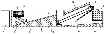
FIG. 1 is a schematic structural diagram of the present invention.
FIG. 2 is a schematic view of the structure of the rinse tank of the present invention.
Fig. 3 is a schematic view of the structure of the rinsing bath of the present invention.
Fig. 4 is an enlarged schematic view of a portion a in fig. 2.
Fig. 5 is a perspective view of a rinse tank of the present invention.
Fig. 6 is a schematic view of the internal structure of the rinsing tank of the present invention.
Fig. 7 is a schematic structural view of a draining tank of the present invention.
Description of reference numerals: the device comprises a rinsing pool 1, a slope I11, a water inlet 12, a water outlet I13, a flushing pool 2, a slope II 21, a water outlet II 22, a discharge port 23, a material separating plate 24, a water baffle 25, a material stacking port 26, a feeding channel 27, a linear driving assembly 3, a sliding block 31, a rinsing tank 4, a bottom plate 41, a sub-tank 42, a leakage hole 421, a slag discharge hole 422, a channel 43, a pressure plate 44, a water through hole 441, a wedge block 442, a cleaning wool ball 45, a rotating mechanism 5, an upper tray body 51, a lower tray body 52, a waterproof motor 53, a box turning mechanism 6, a base 61, a first connecting rod 62, a second connecting rod 63, a third connecting rod 64, a second pivot seat 65, a multi-stage telescopic rod 66, a baffle 67, a first magnetic block 68, a second magnetic block 69, sewage treatment equipment 7, a conveying belt 8, a water draining hole I81, a water draining tank 9, a hanging plate 91, a water draining hole II 92, a spraying frame 10 and a spray head 101.
Detailed Description
The embodiments of the invention will be described in detail below with reference to the drawings, but the invention can be implemented in many different ways as defined and covered by the claims.
The invention is further explained with reference to fig. 1 to 7, and as shown in fig. 1, the vegetable cleaning device for vegetable production comprises a rinsing pool 1, a washing pool 2, a linear driving component 3, a rinsing tank 4, a rotating mechanism 5, a tank turning mechanism 6, a sewage treatment device 7, a conveying mechanism, a draining tank 9 and a spray rack 10, wherein the washing pool 2 is arranged at the right side of the rinsing pool 1, the rinsing tank 4 is arranged in the rinsing pool 1, the rotating mechanism 5 is arranged at the bottom of the rinsing tank 4, the rotating mechanism 5 is used for driving the rinsing tank 4 to rotate, the linear driving component 3 is arranged in the rinsing pool 1, the linear driving component 3 is used for driving the rinsing tank 4 to reciprocate between a feeding station and a discharging station, the feeding station is arranged at the left side of the rinsing pool 1, the discharging station is arranged at the right side of the rinsing pool 1, the tank turning mechanism 6 is arranged in the rinsing pool 1, the tank turning mechanism 6 is used for turning over the rinsing tank 4 to discharge vegetables, conveying mechanism includes driving motor, driving pulley, driven pulleys and conveyer belt 8, 8 covers of conveyer belt are established on driving pulley and driven pulleys, driving motor's output shaft and driving pulley are connected, 8 slopes of conveyer belt set up in rinsing bath 2, and the height that highly is higher than the left end of the right-hand member of conveyer belt 8, be provided with a plurality of waterlogging caused by excessive rainfall hole 81 on the conveyer belt 8, draining box 9 hangs in rinsing bath 2, and draining box 9 is located the below of the unloading end of conveyer belt 8, be provided with a plurality of waterlogging caused by excessive rainfall hole two 92 on the draining box 9, spray rack 10 parallel arrangement is in the top of conveyer belt 8, the bottom of spray rack 10 is provided with a plurality of shower nozzle 101, sewage treatment device 7 is used for handling sewage in order to realize the cyclic utilization of water.
As shown in fig. 2, a slope I11 is arranged at the bottom of a rinsing pool 1, the right end of the slope I11 is higher than the left end of the slope I11, a water inlet 12 of the rinsing pool 1 is arranged at the right side of the rinsing pool 1 and close to the right end of the slope I11, a water outlet I13 of the rinsing pool 1 is arranged at the bottom of the left side of the rinsing pool 1 and close to the left end of the slope I11, a linear driving assembly 3 comprises a rodless cylinder which is fixedly arranged on the slope I11, the arrangement of the slope I11 is convenient for discharging sewage in the rinsing pool 1, and the height of the rinsing tank 4 can be increased in the process that the linear driving assembly 3 drives the rinsing tank 4 to move from a feeding station to a discharging station, so that the rinsing tank 4 is separated from water.
As shown in fig. 2 and 4, the rotating mechanism 5 comprises an upper tray body 51, a lower tray body 52 and a waterproof motor 53, the upper tray body 51 is rotatably arranged on the lower tray body 52, the waterproof motor 53 is fixedly arranged on the lower tray body 52, the waterproof motor 53 can drive the upper tray body 51 to rotate relative to the lower tray body 52, the rinsing tank 4 is detachably arranged on the top of the upper tray body 51, the rotating mechanism 5 drives the rinsing tank 4 to rapidly rotate in the rinsing tank 1, so that the speed of water flow on the surface of vegetables can be increased, the cleaning effect is improved, and meanwhile, the centrifugal washing machine is beneficial to throwing heavier impurities such as gravels out of the rinsing tank 4 under the action of centrifugal force.
As shown in fig. 2 and 4, the box turning mechanism 6 includes a base 61, a pair of first connecting rods 62, a pair of second connecting rods 63, a pair of third connecting rods 64, a multi-stage telescopic rod 66, a baffle 67, a first magnetic block 68 and a second magnetic block 69, the base 61 is fixedly mounted on the slider 31 of the rodless cylinder, the lower ends of the pair of first connecting rods 62 are respectively pivoted on the base 61 through the corresponding first pivoting seats, the upper ends of the pair of first connecting rods 62 are respectively pivoted on the corresponding second pivoting seats 65 at the bottom of the lower plate 52, the lower ends of the pair of second connecting rods 63 are respectively pivoted on the base 61 through the corresponding pair of third pivoting seats, the third pivoting seats are located at the left side of the corresponding first pivoting seats, the second connecting rods 63 are arranged in parallel to the corresponding first connecting rods 62, the pair of third connecting rods 64 are respectively pivoted between the upper ends of the corresponding first connecting rods 62 and the upper ends of the corresponding second connecting rods 63, the lower ends of the multi-stage telescopic rod 66 are pivoted on the base 61 through the fourth pivoting seats, the fourth pivot seat is positioned at the left side of the third pivot seat, the upper end of the multi-stage telescopic rod 66 is pivoted on a fifth pivot seat at the bottom of the lower tray body 52, the fifth pivot seat is positioned at the left side of the second pivot seat 65, the baffle plate 67 is fixedly arranged at the right end part of the base 61, the baffle plate 67 can be abutted against the right sides of the pair of first connecting rods 62 to limit the rotating range of the pair of first connecting rods 62, the first magnetic block 68 is fixedly arranged at the top of the left ends of the pair of third connecting rods 64, the first magnetic block 68 can be adsorbed on the lower tray body 52, the second magnetic block 69 is fixedly arranged on the baffle plate 67, the second magnetic block 69 can be adsorbed on the first connecting rods 62, when the rinsing box 4 needs to be turned over, the multi-stage telescopic rod 66 extends, because the first magnetic block 68 adsorbs and fixes the lower tray body 52 on the third connecting rod 64, the multi-stage telescopic rod 66 extends to enable the first connecting rods 62 and the second connecting rods 63 to rotate, and further drive the height of the rinsing box 4 to rise, until the first connecting rod 62 abuts against the baffle plate 67, the second magnet 69 adsorbs and fixes the first connecting rod 62 on the baffle plate 67, then the rinsing tank 4 rotates with the second pivot seat 65 as a pivot against the magnetic force of the first magnet 68 along with the continuous extension of the multi-stage telescopic rod 66, so that the rinsing tank 4 is turned over, when the rinsing tank 4 is reset, the multi-stage telescopic rod 66 is shortened, and because the second magnet 69 adsorbs and fixes the first connecting rod 62 on the baffle plate 67, the multi-stage telescopic rod 66 is shortened, so that the rinsing tank 4 reversely rotates with the second pivot seat 65 as a pivot until the lower tray body 52 is adsorbed and fixed on the third connecting rod 64 again by the first magnet 68, and then along with the continuous shortening of the multi-stage telescopic rod 66, the first connecting rod 62 and the second connecting rod 63 reversely rotate to drive the rinsing tank 4 to move downwards.
As shown in fig. 5 and 6, the rinsing tank 4 comprises a bottom plate 41 and five sub-tanks 42, the five sub-tanks 42 are arranged on the bottom plate 41 at intervals, a channel 43 is formed between every two adjacent sub-tanks 42, a plurality of leakage holes 421 are formed in the side walls of the sub-tanks 42, the leakage holes 421 and the channel 43 are arranged to facilitate water flow to enter the sub-tanks 42 to wash vegetables, the cleaning effect is improved, the vegetable accumulation in the rinsing tank 4 can be reduced due to the arrangement of the sub-tanks 42, and the problem that the vegetables cannot be cleaned due to the accumulation of the vegetables is avoided.
Further, the number of sub-boxes 42 may be set to two, three, four, six, seven, etc., as actually required.
Preferably, the bottom of the side wall of the sub-tank 42 is provided with a slag discharge hole 422, the bottom of the slag discharge hole 422 is flush with the bottom plate 41, the arrangement of the slag discharge hole 422 is beneficial to flushing soil and sand deposited at the bottom of the sub-tank 42 out of the sub-tank 42, and the cleaning effect is improved.
Preferably, hang on the inner wall of subbox 42 and be equipped with a plurality of washing hair bulb 45, wash hair bulb 45 and be globular brush, rotate the in-process at rinsing case 4, wash hair bulb 45 and can scrub the surface of vegetables at the random activity of subbox 42, promote the cleaning performance.
Preferably, the rinsing tank 4 further comprises a pressure plate 44, five wedges 442 correspondingly matched with the five sub-tanks 42 one by one are arranged at the bottom of the pressure plate 44, the five wedges 442 can be respectively inserted into the corresponding sub-tanks 42, and when vegetables which easily float on water are cleaned, the pressure plate 44 is buckled above the rinsing tank 4, so that the vegetables can be prevented from floating out of the rinsing tank 4 under the action of buoyancy.
Preferably, five groups of water through holes 441 are formed in the pressure plate 44, and the five groups of water through holes 441 are respectively communicated with the five sub-tanks 42.
As shown in fig. 3 and 7, a second slope 21 is arranged at the bottom of the flushing tank 2, the right end of the second slope 21 is higher than the left end so as to facilitate the outflow of sewage from a second drainage outlet 22 at the bottom of the left side of the flushing tank 2, a material separation plate 24 is arranged in the flushing tank 2, a material stacking port 26 is formed between the material separation plate 24 and the left side wall of the flushing tank 2, a material loading channel 27 is formed between the lower end of the material separation plate 24 and the upper side of the conveying belt 8, the material loading channel 27 is arranged to prevent a large amount of vegetables from being stacked on the conveying belt 8, the draining tank 9 is hung on the flushing tank 2 through a pair of hanging plates 91 arranged at the top of the draining tank, and a material discharging port 23 facilitating the loading and unloading of the draining tank 9 is arranged on the right side wall of the flushing tank 2.
Preferably, in order to prevent water from splashing on the draining tank 9, a water baffle 25 is obliquely arranged below the conveying belt 8, and the height of the right end of the water baffle 25 is higher than that of the left end.
As shown in figure 1, in use, a worker pours vegetables into a rinsing tank 4 from a loading station of a rinsing tank 1, then a waterproof motor 53 of a rotating mechanism 5 is started, the waterproof motor 53 drives the rinsing tank 4 to rotate rapidly in the rinsing tank 1, water flow is accelerated to wash the surfaces of the vegetables, soil, gravels and vegetable surfaces attached to the surfaces of the vegetables are stripped, meanwhile, a linear driving assembly 3 drives the rinsing tank 4 to move slowly from the loading station to a blanking station, clean water continuously enters the rinsing tank 1 from a water inlet 12 of the rinsing tank 1 during cleaning, sewage generated by cleaning is continuously discharged from a water outlet 13 of the rinsing tank 1, the rinsing effect is ensured, after rinsing is completed, the rinsing tank 4 is located at the blanking station, then a multi-stage telescopic rod 66 of a box turning mechanism 6 is extended to drive the rinsing tank 4 to turn over, so that the vegetables are slowly poured into a stockpile opening 26 of a rinsing tank 2, rinsing case 4 resets afterwards and returns the material loading station and carry out the washing of next batch vegetables, saves time, and the vegetables that pile up in windrow mouth 26 pass through the below of spray rack 10 gradually slowly under the transport of conveyer belt 8, and shower nozzle 101 on the spray rack 10 sprays the clear water constantly and erodees the vegetables surface, makes vegetables surface cleaning, and later, vegetables cross the upper end of conveyer belt 8 and fall into in waterlogging caused by excessive rainfall box 9, treat that vegetables accomplish after the waterlogging caused by excessive rainfall operation, the abluent vegetables are unloaded from discharge opening 23 along with waterlogging caused by excessive rainfall box 9.
This vegetables belt cleaning device is used in vegetables production can replace artifical completion to the cleaning work of vegetables, has reduced workman's intensity of labour, and work efficiency is higher.
The above is only a preferred embodiment of the present invention, and is not intended to limit the present invention, and various modifications and changes will occur to those skilled in the art. Any modification, equivalent replacement, or improvement made within the spirit and principle of the present invention should be included in the protection scope of the present invention.
Claims (5)
1. A vegetable cleaning device for vegetable production comprises a rinsing tank (1) and a rinsing tank (2), and is characterized by further comprising:
the rinsing tank (4) is arranged in the rinsing pool (1), the rinsing tank (4) comprises a bottom plate (41), a plurality of sub-tanks (42) and a pressure plate (44), the sub-tanks (42) are arranged on the bottom plate (41) at intervals, a channel (43) is formed between every two adjacent sub-tanks (42), a plurality of leakage holes (421) are formed in the side walls of the sub-tanks (42), a plurality of cleaning hair balls (45) are hung on the inner walls of the sub-tanks (42), a plurality of wedge blocks (442) which are matched with the sub-tanks (42) in a one-to-one correspondence mode are arranged at the bottom of the pressure plate (44), and the wedge blocks (442) can be inserted into the corresponding sub-tanks (42);
the rotating mechanism (5), the rotating mechanism (5) is installed at the bottom of the rinsing tank (4) and is used for driving the rinsing tank (4) to rotate;
the linear driving assembly (3) is used for driving the rinsing box (4) to reciprocate between the feeding station and the discharging station;
a box overturning mechanism (6), wherein the box overturning mechanism (6) is used for overturning the rinsing box (4) to realize vegetable blanking, and the box overturning mechanism (6) comprises:
the base (61), the said base (61) is fixed on the slide block (31) of the said linear drive assembly (3);
the lower end of the first connecting rod (62) is pivoted on the base (61) through a first pivoting seat, and the upper end of the first connecting rod (62) is pivoted on a second pivoting seat (65) at the bottom of the lower disc body (52) of the rotating mechanism (5);
the lower end of the second connecting rod (63) is pivoted on the base (61) through a third pivoting seat, the third pivoting seat is positioned on the left side of the first pivoting seat, and the second connecting rod (63) is arranged in parallel relative to the first connecting rod (62);
a third link (64), the third link (64) being pivotally connected between an upper end of the first link (62) and an upper end of the second link (63);
the lower end of the multi-stage telescopic rod (66) is pivoted on the base (61) through a fourth pivoting seat, the fourth pivoting seat is positioned on the left side of the third pivoting seat, the upper end of the multi-stage telescopic rod (66) is pivoted on a fifth pivoting seat at the bottom of the lower tray body (52), and the fifth pivoting seat is positioned on the left side of the second pivoting seat (65);
the baffle (67) is fixedly arranged on the right end part of the base (61), and the baffle (67) can abut against the right side of the first connecting rod (62) to limit the rotating range of the first connecting rod (62);
the first magnetic block (68) is fixedly arranged on the third connecting rod (64), the first magnetic block (68) can be adsorbed on the lower tray body (52), the second magnetic block (69) is fixedly arranged on the baffle plate (67), and the second magnetic block (69) can be adsorbed on the first connecting rod (62);
the conveying belt (8), the conveying belt (8) is obliquely arranged in the flushing tank (2);
the spraying frame (10) is arranged above the conveying belt (8) in parallel, and a plurality of spray heads (101) are arranged at the bottom of the spraying frame (10);
the sewage treatment equipment (7) is used for treating sewage to realize the recycling of water.
2. The vegetable cleaning device for vegetable production as defined in claim 1, wherein the rotating mechanism (5) comprises an upper tray body (51), a lower tray body (52) and a waterproof motor (53), the upper tray body (51) is rotatably arranged on the lower tray body (52), the waterproof motor (53) is fixedly arranged on the lower tray body (52), and the waterproof motor (53) can drive the upper tray body (51) to rotate relative to the lower tray body (52).
3. Vegetable washing device for vegetable production according to claim 1, characterized in that the bottom of the rinsing tank (1) is provided with a first ramp (11), the linear drive assembly (3) being arranged on the first ramp (11).
4. The vegetable washing device for vegetable production as claimed in claim 1, wherein a bottom of a side wall of the sub-tank (42) is provided with a residue discharge hole (422).
5. Vegetable washing device for vegetable production according to claim 1, characterized in that it further comprises a draining tank (9), said draining tank (9) being suspended inside said washing basin (2), and said draining tank (9) being located below the blanking end of said conveyor belt (8).
Priority Applications (1)
| Application Number | Priority Date | Filing Date | Title |
|---|---|---|---|
| CN202010652992.1A CN111758977B (en) | 2020-07-08 | 2020-07-08 | Vegetable cleaning device for vegetable production |
Applications Claiming Priority (1)
| Application Number | Priority Date | Filing Date | Title |
|---|---|---|---|
| CN202010652992.1A CN111758977B (en) | 2020-07-08 | 2020-07-08 | Vegetable cleaning device for vegetable production |
Publications (2)
| Publication Number | Publication Date |
|---|---|
| CN111758977A CN111758977A (en) | 2020-10-13 |
| CN111758977B true CN111758977B (en) | 2022-04-26 |
Family
ID=72726144
Family Applications (1)
| Application Number | Title | Priority Date | Filing Date |
|---|---|---|---|
| CN202010652992.1A Active CN111758977B (en) | 2020-07-08 | 2020-07-08 | Vegetable cleaning device for vegetable production |
Country Status (1)
| Country | Link |
|---|---|
| CN (1) | CN111758977B (en) |
Families Citing this family (2)
| Publication number | Priority date | Publication date | Assignee | Title |
|---|---|---|---|---|
| CN115956683B (en) * | 2023-03-16 | 2023-05-16 | 辽宁东麟科技有限公司 | Cleaning screening machine for agricultural product processing |
| CN117481360B (en) * | 2024-01-03 | 2024-04-16 | 江苏森德有机农业发展有限公司 | Vegetable processing device with spray cleaning structure |
Citations (5)
| Publication number | Priority date | Publication date | Assignee | Title |
|---|---|---|---|---|
| JPH1057033A (en) * | 1996-08-16 | 1998-03-03 | Mitsubishi Heavy Ind Ltd | Apparatus for cleaning, arranging and transporting agricultural product |
| JP2002085036A (en) * | 2000-09-07 | 2002-03-26 | Matsushita Refrig Co Ltd | Cleaning machine |
| CN108393285A (en) * | 2018-03-06 | 2018-08-14 | 中铁局集团有限公司 | A kind of block pulp folder cleaning machine |
| CN108903020A (en) * | 2018-07-20 | 2018-11-30 | 芜湖碧水谣医疗设备科技有限公司 | A kind of belt all automatic vegetables cleaning machine |
| CN210339147U (en) * | 2019-05-13 | 2020-04-17 | 江苏绿博生物科技有限公司 | Feeding tipping bucket mechanism |
Family Cites Families (2)
| Publication number | Priority date | Publication date | Assignee | Title |
|---|---|---|---|---|
| CN209346044U (en) * | 2018-09-14 | 2019-09-06 | 民乐县福园菌业有限公司 | A kind of mushroom cleaning draining device |
| CN210471963U (en) * | 2019-06-18 | 2020-05-08 | 北京稻香村食品有限责任公司 | Simple vegetable washing machine |
-
2020
- 2020-07-08 CN CN202010652992.1A patent/CN111758977B/en active Active
Patent Citations (5)
| Publication number | Priority date | Publication date | Assignee | Title |
|---|---|---|---|---|
| JPH1057033A (en) * | 1996-08-16 | 1998-03-03 | Mitsubishi Heavy Ind Ltd | Apparatus for cleaning, arranging and transporting agricultural product |
| JP2002085036A (en) * | 2000-09-07 | 2002-03-26 | Matsushita Refrig Co Ltd | Cleaning machine |
| CN108393285A (en) * | 2018-03-06 | 2018-08-14 | 中铁局集团有限公司 | A kind of block pulp folder cleaning machine |
| CN108903020A (en) * | 2018-07-20 | 2018-11-30 | 芜湖碧水谣医疗设备科技有限公司 | A kind of belt all automatic vegetables cleaning machine |
| CN210339147U (en) * | 2019-05-13 | 2020-04-17 | 江苏绿博生物科技有限公司 | Feeding tipping bucket mechanism |
Also Published As
| Publication number | Publication date |
|---|---|
| CN111758977A (en) | 2020-10-13 |
Similar Documents
| Publication | Publication Date | Title |
|---|---|---|
| CN111758977B (en) | Vegetable cleaning device for vegetable production | |
| CN203538317U (en) | Vegetable and fruit cleaning machine | |
| CN103494311A (en) | Vegetable and fruit cleaning machine | |
| CN111764361B (en) | Comprehensive cleaning method for pump station forebay | |
| CN210782846U (en) | Vegetable cleaning device | |
| KR20200120117A (en) | A Water saving bulb washer | |
| CN209693996U (en) | A kind of exclusion device of fruit-vegetable cleaner | |
| CN205512215U (en) | Sheller is washd to bean sprouts | |
| KR200200067Y1 (en) | Bean sprouts washer | |
| CN211379565U (en) | Bamboo shoot shell cleaning device | |
| CN109393517B (en) | Artichoke belt cleaning device that accessible floats salvage volume of twin-buds hierarchical | |
| CN108887703B (en) | Mushroom cleaning equipment | |
| CN211153714U (en) | Mushroom cleaning device | |
| CN214431618U (en) | Hot pepper belt cleaning device | |
| CN2495121Y (en) | Machine for removing hair or impurities for raw material of soft food | |
| JP2000050796A (en) | Apparatus for washing fresh tea leaf | |
| CN210538769U (en) | Cleaning device for effectively protecting tuber peel | |
| KR100436106B1 (en) | Bean sprouts washer | |
| CN112741342A (en) | Intelligent stain detection gradient cleaning equipment for fruits and vegetables | |
| CN113319021A (en) | High-efficient separator that washs of trichosanthes seed | |
| KR200230280Y1 (en) | Bean sprouts washer | |
| CN210120877U (en) | Aquatic products raw materials belt cleaning device | |
| CN201515681U (en) | Fruits and vegetables cleaning machine | |
| CN213549578U (en) | Apple cleaning machine | |
| CN208480570U (en) | A kind of lycium ruthenicum, the quick impurity elimination cleaning device of fructus hippophae |
Legal Events
| Date | Code | Title | Description |
|---|---|---|---|
| PB01 | Publication | ||
| PB01 | Publication | ||
| SE01 | Entry into force of request for substantive examination | ||
| SE01 | Entry into force of request for substantive examination | ||
| GR01 | Patent grant | ||
| GR01 | Patent grant |