CN111576403B - Pile splicing structure and bearing platform anchoring structure using PHC tubular pile - Google Patents
Pile splicing structure and bearing platform anchoring structure using PHC tubular pile Download PDFInfo
- Publication number
- CN111576403B CN111576403B CN202010429498.9A CN202010429498A CN111576403B CN 111576403 B CN111576403 B CN 111576403B CN 202010429498 A CN202010429498 A CN 202010429498A CN 111576403 B CN111576403 B CN 111576403B
- Authority
- CN
- China
- Prior art keywords
- steel
- pile
- steel sleeve
- sleeve
- end plate
- Prior art date
- Legal status (The legal status is an assumption and is not a legal conclusion. Google has not performed a legal analysis and makes no representation as to the accuracy of the status listed.)
- Active
Links
- 238000004873 anchoring Methods 0.000 title claims abstract description 17
- 229910000831 Steel Inorganic materials 0.000 claims abstract description 165
- 239000010959 steel Substances 0.000 claims abstract description 165
- 239000011440 grout Substances 0.000 claims abstract description 22
- 238000003466 welding Methods 0.000 claims abstract description 13
- 230000000149 penetrating effect Effects 0.000 claims abstract description 4
- 239000004567 concrete Substances 0.000 claims description 20
- 238000004891 communication Methods 0.000 claims description 17
- 239000000463 material Substances 0.000 claims description 17
- 238000009826 distribution Methods 0.000 claims description 3
- 238000010276 construction Methods 0.000 abstract description 11
- 239000011372 high-strength concrete Substances 0.000 abstract description 6
- 230000007547 defect Effects 0.000 abstract description 3
- 230000000694 effects Effects 0.000 abstract description 2
- 238000009417 prefabrication Methods 0.000 abstract description 2
- 230000033764 rhythmic process Effects 0.000 abstract description 2
- 238000000034 method Methods 0.000 description 8
- 210000001503 joint Anatomy 0.000 description 7
- 230000002787 reinforcement Effects 0.000 description 6
- 238000004519 manufacturing process Methods 0.000 description 5
- 238000009434 installation Methods 0.000 description 3
- 239000002002 slurry Substances 0.000 description 3
- 239000000243 solution Substances 0.000 description 3
- CURLTUGMZLYLDI-UHFFFAOYSA-N Carbon dioxide Chemical compound O=C=O CURLTUGMZLYLDI-UHFFFAOYSA-N 0.000 description 2
- 229910001294 Reinforcing steel Inorganic materials 0.000 description 2
- 238000005452 bending Methods 0.000 description 2
- 238000002347 injection Methods 0.000 description 2
- 239000007924 injection Substances 0.000 description 2
- 238000006467 substitution reaction Methods 0.000 description 2
- 230000009286 beneficial effect Effects 0.000 description 1
- 229910002092 carbon dioxide Inorganic materials 0.000 description 1
- 239000001569 carbon dioxide Substances 0.000 description 1
- 230000007797 corrosion Effects 0.000 description 1
- 238000005260 corrosion Methods 0.000 description 1
- 238000010586 diagram Methods 0.000 description 1
- 230000009189 diving Effects 0.000 description 1
- 238000010891 electric arc Methods 0.000 description 1
- 238000011065 in-situ storage Methods 0.000 description 1
- 238000003754 machining Methods 0.000 description 1
- 239000011150 reinforced concrete Substances 0.000 description 1
Images

Classifications
-
- E—FIXED CONSTRUCTIONS
- E02—HYDRAULIC ENGINEERING; FOUNDATIONS; SOIL SHIFTING
- E02D—FOUNDATIONS; EXCAVATIONS; EMBANKMENTS; UNDERGROUND OR UNDERWATER STRUCTURES
- E02D5/00—Bulkheads, piles, or other structural elements specially adapted to foundation engineering
- E02D5/22—Piles
- E02D5/52—Piles composed of separable parts, e.g. telescopic tubes ; Piles composed of segments
- E02D5/523—Piles composed of separable parts, e.g. telescopic tubes ; Piles composed of segments composed of segments
- E02D5/526—Connection means between pile segments
-
- E—FIXED CONSTRUCTIONS
- E02—HYDRAULIC ENGINEERING; FOUNDATIONS; SOIL SHIFTING
- E02D—FOUNDATIONS; EXCAVATIONS; EMBANKMENTS; UNDERGROUND OR UNDERWATER STRUCTURES
- E02D27/00—Foundations as substructures
- E02D27/10—Deep foundations
- E02D27/12—Pile foundations
- E02D27/14—Pile framings, i.e. piles assembled to form the substructure
-
- E—FIXED CONSTRUCTIONS
- E02—HYDRAULIC ENGINEERING; FOUNDATIONS; SOIL SHIFTING
- E02D—FOUNDATIONS; EXCAVATIONS; EMBANKMENTS; UNDERGROUND OR UNDERWATER STRUCTURES
- E02D5/00—Bulkheads, piles, or other structural elements specially adapted to foundation engineering
- E02D5/22—Piles
- E02D5/58—Prestressed concrete piles
-
- E—FIXED CONSTRUCTIONS
- E02—HYDRAULIC ENGINEERING; FOUNDATIONS; SOIL SHIFTING
- E02D—FOUNDATIONS; EXCAVATIONS; EMBANKMENTS; UNDERGROUND OR UNDERWATER STRUCTURES
- E02D2600/00—Miscellaneous
- E02D2600/20—Miscellaneous comprising details of connection between elements
Abstract
The invention relates to the field of prestressed high-strength concrete pipe pile structures of civil engineering pile foundations, in particular to a pile extension structure and a bearing platform anchoring structure using PHC (prestressed high-strength concrete) pipe piles. The end plate is characterized in that a plurality of steel sleeves are arranged on the lower end face of the end plate, communicating pipelines are arranged between the lower portions of the adjacent steel sleeves, the inner cavity of each communicating pipeline is communicated with the inner cavity of the adjacent steel sleeve, a through hole allowing a prestressed steel bar to penetrate is formed in the bottom face of each steel sleeve, the end portion of the prestressed steel bar penetrating into the steel sleeve is in stop fit with the bottom face of the steel sleeve, and a grouting hole and a grout outlet hole are formed in the end plate in a radially distributed mode. The invention can be used for the anti-pulling connection of the pile body of the PHC pipe pile and the reliable connection of the PHC pipe pile and the bearing platform, and can adapt to the construction rhythm of prefabrication and assembly of the bearing platform. The defects of end plate welding connection and mechanical connection are overcome, pile splicing operation precision requirement is low, the pile splicing device is suitable for complex engineering conditions, and the effect is guaranteed.
Description
Technical Field
The invention relates to the field of prestressed high-strength concrete pipe pile structures of civil engineering pile foundations, in particular to a pile extension structure and a bearing platform anchoring structure using PHC (prestressed high-strength concrete) pipe piles.
Background
The prestressed high-strength concrete pipe pile (PHC pipe pile) has the characteristics of good pile body quality, high vertical bearing capacity of a single pile, strong adaptability to engineering geological conditions, high construction speed and the like. Since the last 90 s, the method is widely applied to projects such as buildings, roads, railways, ports and the like in China. The pile length of the prestressed high-strength concrete pipe pile often cannot meet the design requirement at one time due to the reasons of production, transportation, construction and the like, and the pile must be spliced on site during pile driving, which relates to the problem of pipe pile joint. Meanwhile, under the working condition that the tubular pile foundation is resistant to pulling and bears, the tubular pile head and a cast-in-place reinforced concrete bearing platform or foundation need to be reliably connected in a pulling-resistant manner, and the problem of connection of the pile head nodes is also involved.
At present, the connecting method of the PHC tubular pile body mainly comprises two main forms of end plate welding connection and mechanical joint connection. After the end plates of the upper tubular pile and the lower tubular pile are aligned and attached tightly in the end plate welding connection, a cut-open part is reserved on the outer edge of each end plate, manual electric arc welding or carbon dioxide protection welding is adopted for welding, and the number of welding layers is preferably 3. Mechanical joint connections now take three main forms: mechanical threaded joints, mechanical engagement joints, and hoop style joints. The mechanical joints have more connection forms and different structures, but the starting point is to save the pile connecting time and meet the requirements of various stress performances of the pile section and the joint corrosion resistance in the construction.
Generally, compared with mechanical joint connection, the end plate welding connection structure is simple, materials are economical, manufacturing and processing are convenient, connection tightness is good, and the operation method is mature. However, the method is greatly influenced by site construction conditions, worker skill level and working attitude, has more uncertain factors, uneven welding level, an end plate heat affected zone and lower control degree of welding seam quality. The mechanical joint connection has the obvious advantages of saving pile connecting time, but has the defects of complicated joint manufacturing, complicated connection structure, high manufacturing cost, limited field construction, unsuitability for pile sinking in a hammering mode and poor joint closure.
Disclosure of Invention
The invention provides a sleeve end plate for realizing grouting connection and a PHC tubular pile, aiming at solving various problems of the existing connection method of a PHC tubular pile body.
The invention is realized by the following technical scheme: a sleeve end plate for realizing grout is connected, including the annular end plate of circle, be equipped with a plurality of steel sleeves on the lower terminal surface of end plate with prestressing steel stick one-to-one, set up the connecting hole of intercommunication steel sleeve inner chamber on the end plate relative with the steel sleeve, be equipped with the intercommunication pipeline between the adjacent steel sleeve lower part, every intercommunication pipeline inner chamber is linked together with adjacent steel sleeve inner chamber, and the through-hole that allows the prestressing steel stick to penetrate is seted up to every steel sleeve bottom surface, and the tip of the prestressing steel stick that penetrates the steel sleeve ends with the steel sleeve bottom surface and ends the position cooperation, an injection hole and a grout outlet have been seted up to end plate inside along radial distribution, and the injection hole is linked together with one of them steel sleeve inner chamber, and grout outlet is linked together with arbitrary one of steel sleeve inner chamber in other steel sleeves.
As a further improvement of the technical scheme of the invention, the center line of each steel sleeve is vertical to the end plate.
As a further improvement of the technical scheme of the invention, the bottom of each steel sleeve positioned below the communication pipeline is of a conical head structure.
As a further improvement of the technical scheme of the invention, the communication pipelines between the adjacent steel sleeves jointly enclose an annular communication channel.
As a further improvement of the technical scheme of the invention, the center line of each connecting hole and the center line of the steel sleeve opposite to the connecting hole are positioned on the same vertical line, and the diameter of each connecting hole is equal to the inner diameter of the steel sleeve opposite to the connecting hole.
As a further improvement of the technical scheme of the invention, the grouting holes and the grout outlet holes are opposite in the radial direction of the end plate.
The invention further provides a PHC tubular pile using the sleeve end plate for realizing grouting connection, which comprises a concrete tubular pile, a plurality of prestressed steel rods preset in the concrete tubular pile and the sleeve end plate arranged at the end part of the concrete tubular pile and used for realizing grouting connection, wherein the steel sleeve and the communication pipeline are prefabricated in the pile body of the concrete tubular pile.
The invention further provides a pile splicing structure using the PHC tubular piles, which comprises at least two sections of butted PHC tubular piles, wherein end plates of adjacent PHC tubular piles are welded and connected, connecting holes between the adjacent PHC tubular piles are opposite, anchoring connecting steel bars are commonly penetrated and arranged in steel sleeves opposite to the adjacent PHC tubular piles, and grouting materials are filled in the steel sleeves, the communicating pipelines and the connecting holes of the adjacent PHC tubular piles.
The invention further provides a bearing platform anchoring structure using the PHC tubular pile, which comprises the PHC tubular pile and a bearing platform foundation, wherein an anchoring connecting steel bar penetrates through each steel sleeve of the PHC tubular pile, the upper end of each anchoring connecting steel bar extends out of the connecting hole and is connected with the bearing platform foundation, and grouting materials are filled in the steel sleeves, the communicating pipelines and the connecting holes of the PHC tubular pile.
The sleeve end plate for realizing grouting connection adopts a method of grouting materials in the steel sleeve to realize the connection of the anchoring connection reinforcing steel bars and the prestressed steel bars, and the space structure formed by the steel sleeve and the end plate improves the bending rigidity of the pile head end plate and is beneficial to the bending resistance of the pile head. The method can be used for the anti-pulling connection of the pile body of the PHC pipe pile, can also be used for the reliable connection of the PHC pipe pile and a bearing platform (or a foundation), and can adapt to the prefabrication and assembly construction rhythm of the bearing platform (or the foundation). The defects of end plate welding connection and mechanical connection are overcome, pile splicing operation precision requirement is low, the pile splicing device is suitable for complex engineering conditions, and the effect is guaranteed.
Drawings
In order to more clearly illustrate the embodiments of the present invention or the technical solutions in the prior art, the drawings used in the description of the embodiments or the prior art will be briefly described below, it is obvious that the drawings in the following description are only some embodiments of the present invention, and for those skilled in the art, other drawings can be obtained according to the drawings without creative efforts.
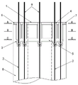
Fig. 1 is a schematic structural view of the PHC pile of the present invention.
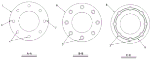
FIG. 2 is a cross-sectional view of A-A, B-B, C-C.
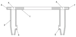
Fig. 3 is a longitudinal section of the sleeve end plate for making a grout joint.
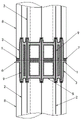
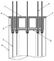
Fig. 4 is a pile splicing structure schematic diagram of the PHC pile.
Fig. 5 is a schematic view of a cushion cap anchoring structure of the PHC pile.
FIG. 6 is a schematic structural view of a T-shaped mounting hole and a through hole at the bottom of a steel sleeve.
In the figure: 1-end plate, 2-prestressed steel bar, 3-steel sleeve, 4-connecting hole, 5-communicating pipeline, 6-grouting hole, 7-grout outlet, 8-concrete pipe pile, 9-anchoring connecting steel bar and 10-mounting hole.
Detailed Description
In order to make the objects, technical solutions and advantages of the present invention more apparent, the technical solutions of the present invention will be described in detail below. It is to be understood that the described embodiments are merely exemplary of the invention, and not restrictive of the full scope of the invention. All other embodiments, which can be derived by a person skilled in the art from the examples given herein without any inventive step, are within the scope of the present invention.
As shown in fig. 1 to 4, the present embodiment provides a sleeve end plate for implementing a grout joint, comprising a circular end plate 1, a plurality of steel sleeves 3 are arranged on the lower end surface of the end plate 1 corresponding to the prestressed steel bars 2 one by one, the end plate 1 opposite to the steel sleeve 3 is provided with a connecting hole 4 communicated with the inner cavity of the steel sleeve 3, a communicating pipeline 5 is arranged between the lower parts of the adjacent steel sleeves 3, the inner cavity of each communicating pipeline 5 is communicated with the inner cavity of the adjacent steel sleeve 3, the bottom surface of each steel sleeve 3 is provided with a through hole allowing the prestressed steel bar 2 to penetrate, the end part of the prestressed steel bar 2 penetrating into the steel sleeve 3 is in stop fit with the bottom surface of the steel sleeve 3, the end plate 1 is radially and internally provided with a grouting hole 6 and a grout outlet 7, the grouting hole 6 is communicated with the inner cavity of one of the steel sleeves 3, and the grout outlet 7 is communicated with the inner cavity of any one of the other steel sleeves 3.
In the present embodiment, the respective steel sleeves 3 and the communication pipe 5 are communicated with each other, so that the grouting material can be sufficiently filled between the respective steel sleeves 3. In this embodiment, the grouting material is injected through the grouting hole 6, and when the grouting material is discharged from the discharge hole 7, it is considered that the steel sleeve 3 and the grouting material in the communication pipe 5 are filled.
In this embodiment, the prestressed steel bar 2 is in stop fit with the bottom surface of the steel sleeve 3 through a pier head at the end of the prestressed steel bar, but the end of the prestressed steel bar 2 can also be in stop fit with the bottom surface of the steel sleeve 3 through other structures in the field.
In the present embodiment, it is preferable that the center line of each steel sleeve 3 is perpendicular to the end plate 1.
In order to enable the anchoring connection steel bars 9 to be in one-to-one correspondence with the prestressed steel bars 2 in the steel sleeve 3 in the vertical direction or be located on the same straight line in the vertical direction, the bottom of each steel sleeve 3 located below the communication pipeline 5 is of a conical head structure. The inside and the outside of every steel sleeve 3 all are the conical head shape promptly, and when the through-hole on the steel sleeve 3 was located the conical head center, prestressing steel bar 2 was located conical head middle part, and anchor connecting reinforcement 9 was because the spacing of conical head cavity in the steel sleeve 3 for anchor connecting reinforcement 9 is located conical head middle part.
As shown in fig. 2, the communication pipes 5 between the adjacent steel casings 3 together enclose an annular communication passage. Annular intercommunication passageway is horizontal setting, can be parallel with end plate 1 like this, is convenient for in addition prefabricate annular intercommunication passageway in the PHC tubular pile.
As shown in fig. 3, the center line of each connecting hole 4 and the center line of the steel sleeve 3 opposite thereto are located on the same vertical line, and the diameter of each connecting hole 4 is equal to the inner diameter of the steel sleeve 3 opposite thereto.
When the steel sleeves 3 are uniformly distributed on the end plate 1 and the number of the steel sleeves 3 is an even number, the grout holes 6 and the grout outlet holes 7 are opposed in the radial direction of the end plate 1 in order to fill the steel sleeves 3 with the grout material as much as possible. When the number of the steel sleeves 3 is odd, in order to fill the steel sleeves 3 with the grouting material as full as possible, the grouting holes 6 and the grout outlet holes 7 are adjusted to the relative positions in the radial direction of the end plate 1 as much as possible.
As shown in fig. 1, this embodiment still provides a PHC tubular pile that uses the sleeve end plate that is used for realizing the grout connection, including concrete pipe pile 8, preset a plurality of prestressing steel rods 2 in concrete pipe pile 8 and locate the sleeve end plate that is used for realizing the grout connection of 8 tip of concrete pipe pile, steel sleeve 3 and communicating pipe 5 are prefabricated in concrete pipe pile 8's pile body.
As shown in fig. 6, in order to facilitate the pre-installation of the prestressed steel bar 2 in the concrete pipe pile 8, a T-shaped installation hole 10 is formed in the bottom side wall of each steel sleeve 3, and the tail of the installation hole 10 is communicated with the through hole in the bottom surface of the steel sleeve 3. The pier head at the end part of the prestressed steel bar 2 can penetrate into the head part of the mounting hole 10, and the bar body of the prestressed steel bar 2 can be sent into the tail part of the mounting hole 10. After the prestressed steel bar 2 is loosened, the pier head at the end part of the prestressed steel bar 2 falls into the bottom surface of the steel sleeve 3, and the pier head at the end part of the prestressed steel bar 2 is in end-to-end fit with the bottom surface of the steel sleeve 3 in the longitudinal direction and cannot slide out of the tail part of the mounting hole 10 in the transverse direction.
As shown in fig. 4, this embodiment also provides a pile extension structure of PHC tubular pile, including the PHC tubular pile of two sections at least butt joints, the end plate 1 welded connection of adjacent PHC tubular pile, and connecting hole 4 between the adjacent PHC tubular pile is relative, wears to put anchor connecting reinforcement 9 in the steel sleeve 3 that adjacent PHC tubular pile is relative jointly to steel sleeve 3, communicating pipe 5 and connecting hole 4 intussuseption of adjacent PHC tubular pile are filled with grouting material.
Before concrete grouting operation, the end plates 1 of adjacent PHC tubular piles are welded together along the circumferential edge grooves to seal the space of the steel sleeve 3 and prevent slurry leakage in the subsequent pressure grouting process. During concrete grouting operation, pressure grouting is simultaneously carried out on two grouting holes 6 on adjacent PHC tubular piles, the pressure control range is 0.2-0.5MPa, and when slurry is gushed from two slurry outlet holes 7, the grouting material in the pile splicing structure is considered to be filled fully.
As shown in fig. 5, the embodiment further provides a use the cushion cap anchor structure of PHC tubular pile, including PHC tubular pile and cushion cap foundation, anchor connecting reinforcement 9 has all worn to put in every steel sleeve 3 of PHC tubular pile, and the upper end of anchor connecting reinforcement 9 stretches out connecting hole 4 and is connected with the cushion cap foundation, and the steel sleeve 3 of PHC tubular pile, intercommunication pipeline 5 and connecting hole 4 intussuseption are filled with grouting material.
During specific operation, the anchoring connecting steel bars 9 are connected with a steel reinforcement cage of the bearing platform foundation, and grouting operation is directly carried out on the sleeve end plate from top to bottom through the connecting holes 4 until grouting is full. And then pouring a bearing platform foundation in situ to complete the reliable connection of the PHC pipe pile and the bearing platform foundation.
The sleeve end plate has simple structure, moderate manufacturing cost, low requirement on construction precision and low requirement on construction personnel quality and construction environment; because the grouting material for connecting the reinforcing steel bars is mostly hydraulic material, the underwater construction is convenient, and a large amount of welding or diving operation is not needed; the degree of industrialization is high, and the field assembly is simple swift. In addition, the end plate sleeve has low requirement on machining precision and relatively low price.
The above description is only for the specific embodiments of the present invention, but the scope of the present invention is not limited thereto, and any person skilled in the art can easily conceive of the changes or substitutions within the technical scope of the present invention, and all the changes or substitutions should be covered within the scope of the present invention. Therefore, the protection scope of the present invention shall be subject to the protection scope of the appended claims.
Claims (10)
1. A pile splicing structure using PHC tubular piles is characterized by comprising at least two sections of PHC tubular piles which are butted, end plates (1) of adjacent PHC tubular piles are connected in a welding mode, connecting holes (4) between the adjacent PHC tubular piles are opposite, anchoring connecting steel bars (9) penetrate through steel sleeves (3) opposite to the adjacent PHC tubular piles together, and grouting materials are filled in the steel sleeves (3), the communicating pipelines (5) and the connecting holes (4) of the adjacent PHC tubular piles;
the PHC tubular pile comprises a concrete tubular pile (8), a plurality of prestressed steel rods (2) which are preset in the concrete tubular pile (8), and a sleeve end plate which is arranged at the end part of the concrete tubular pile (8) and used for realizing grouting connection, wherein the steel sleeve (3) and the communication pipeline (5) are prefabricated in a pile body of the concrete tubular pile (8);
the sleeve end plate for realizing grouting connection comprises an annular end plate (1), a plurality of steel sleeves (3) are arranged on the lower end face of the end plate (1) in one-to-one correspondence with the prestressed steel bars (2), a connecting hole (4) communicated with the inner cavity of each steel sleeve (3) is formed in the end plate (1) opposite to each steel sleeve (3), a communicating pipeline (5) is arranged between the lower parts of the adjacent steel sleeves (3), the inner cavity of each communicating pipeline (5) is communicated with the inner cavity of the adjacent steel sleeve (3), a through hole allowing the prestressed steel bar (2) to penetrate is formed in the bottom surface of each steel sleeve (3), the end part of the prestressed steel bar (2) penetrating into each steel sleeve (3) is in stop fit with the bottom surface of the steel sleeve (3), a grouting hole (6) and a grout outlet hole (7) are formed in the end plate (1) in a radial distribution manner, and the grouting hole (6) is communicated with the inner cavity of one steel sleeve (3), the grout outlet (7) is communicated with the inner cavity of any one steel sleeve (3) of the other steel sleeves (3); the utility model discloses a steel sleeve (3) bottom lateral wall is seted up and is mounting hole (10) of T style of calligraphy, the afterbody of this mounting hole (10) is linked together with the through-hole of steel sleeve (3) bottom surface, the pier nose of prestressing force steel stick (2) tip can be deepened to the head of mounting hole (10), the barrel of prestressing force steel stick (2) is sent into the afterbody of mounting hole (10), loosen prestressing force steel stick (2) back, the pier nose of prestressing force steel stick (2) tip falls into on steel sleeve (3) bottom surface, and the pier nose of prestressing force steel stick (2) tip ends the cooperation of position stopping with steel sleeve (3) bottom surface on vertical, can' T follow the afterbody roll-off of mounting hole (10) on horizontal.
2. A pile extension structure using PHC pile according to claim 1, wherein the central line of each steel sleeve (3) is perpendicular to the end plate (1).
3. A pile extension structure using PHC pile according to claim 1, characterized in that the bottom of each steel sleeve (3) below the communication pipe (5) is of a cone head structure.
4. A pile extension structure using PHC pile according to claim 1, wherein the communication channels (5) between adjacent steel sleeves (3) together enclose an annular communication channel.
5. A pile extension structure using PHC pile according to claim 1, wherein the center line of each connection hole (4) and the center line of its opposite steel sleeve (3) are located on the same vertical line, and the diameter of each connection hole (4) is equal to the inner diameter of its opposite steel sleeve (3).
6. A pile extension structure using PHC pile according to claim 1, wherein the grout hole (6) and the grout hole (7) are opposite in the radial direction of the end plate (1).
7. A cushion cap anchoring structure using a PHC pipe pile is characterized by comprising the PHC pipe pile and a cushion cap foundation, wherein an anchoring connecting steel bar (9) penetrates through each steel sleeve (3) of the PHC pipe pile, the upper end of each anchoring connecting steel bar (9) extends out of a connecting hole (4) and is connected with the cushion cap foundation, and grouting materials are filled in the steel sleeves (3), the communicating pipelines (5) and the connecting holes (4) of the PHC pipe pile;
the PHC tubular pile comprises a concrete tubular pile (8), a plurality of prestressed steel rods (2) which are preset in the concrete tubular pile (8), and a sleeve end plate which is arranged at the end part of the concrete tubular pile (8) and used for realizing grouting connection, wherein the steel sleeve (3) and the communication pipeline (5) are prefabricated in a pile body of the concrete tubular pile (8);
the sleeve end plate for realizing grouting connection comprises an annular end plate (1), a plurality of steel sleeves (3) are arranged on the lower end face of the end plate (1) in one-to-one correspondence with the prestressed steel bars (2), a connecting hole (4) communicated with the inner cavity of each steel sleeve (3) is formed in the end plate (1) opposite to each steel sleeve (3), a communicating pipeline (5) is arranged between the lower parts of the adjacent steel sleeves (3), the inner cavity of each communicating pipeline (5) is communicated with the inner cavity of the adjacent steel sleeve (3), a through hole allowing the prestressed steel bar (2) to penetrate is formed in the bottom surface of each steel sleeve (3), the end part of the prestressed steel bar (2) penetrating into each steel sleeve (3) is in stop fit with the bottom surface of the steel sleeve (3), a grouting hole (6) and a grout outlet hole (7) are formed in the end plate (1) in a radial distribution manner, and the grouting hole (6) is communicated with the inner cavity of one steel sleeve (3), the grout outlet (7) is communicated with the inner cavity of any one steel sleeve (3) of the other steel sleeves (3); the utility model discloses a steel sleeve (3) bottom lateral wall is seted up and is mounting hole (10) of T style of calligraphy, the afterbody of this mounting hole (10) is linked together with the through-hole of steel sleeve (3) bottom surface, the pier nose of prestressing force steel stick (2) tip can be deepened to the head of mounting hole (10), the barrel of prestressing force steel stick (2) is sent into the afterbody of mounting hole (10), loosen prestressing force steel stick (2) back, the pier nose of prestressing force steel stick (2) tip falls into on steel sleeve (3) bottom surface, and the pier nose of prestressing force steel stick (2) tip ends the cooperation of position stopping with steel sleeve (3) bottom surface on vertical, can' T follow the afterbody roll-off of mounting hole (10) on horizontal.
8. A cap anchor structure using PHC pile according to claim 7, wherein the center line of each steel sleeve (3) is perpendicular to the end plate (1).
9. A cap anchor structure using PHC pile according to claim 7, wherein the bottom of each steel sleeve (3) below the communication pipe (5) is of a cone head structure.
10. The structure of claim 7, wherein the communication pipes (5) between the adjacent steel sleeves (3) together define an annular communication passage.
Priority Applications (1)
| Application Number | Priority Date | Filing Date | Title |
|---|---|---|---|
| CN202010429498.9A CN111576403B (en) | 2020-05-20 | 2020-05-20 | Pile splicing structure and bearing platform anchoring structure using PHC tubular pile |
Applications Claiming Priority (1)
| Application Number | Priority Date | Filing Date | Title |
|---|---|---|---|
| CN202010429498.9A CN111576403B (en) | 2020-05-20 | 2020-05-20 | Pile splicing structure and bearing platform anchoring structure using PHC tubular pile |
Publications (2)
| Publication Number | Publication Date |
|---|---|
| CN111576403A CN111576403A (en) | 2020-08-25 |
| CN111576403B true CN111576403B (en) | 2022-03-29 |
Family
ID=72126954
Family Applications (1)
| Application Number | Title | Priority Date | Filing Date |
|---|---|---|---|
| CN202010429498.9A Active CN111576403B (en) | 2020-05-20 | 2020-05-20 | Pile splicing structure and bearing platform anchoring structure using PHC tubular pile |
Country Status (1)
| Country | Link |
|---|---|
| CN (1) | CN111576403B (en) |
Families Citing this family (6)
| Publication number | Priority date | Publication date | Assignee | Title |
|---|---|---|---|---|
| CN112012202B (en) * | 2020-09-17 | 2023-08-01 | 福建翔达管桩有限公司 | Corrosion-resistant PHC tubular pile |
| CN112343051B (en) * | 2020-11-14 | 2022-04-01 | 中冶成都勘察研究总院有限公司 | Method for rotary digging implantation pile sinking in high backfill region |
| CN112323790B (en) * | 2020-11-18 | 2021-11-16 | 太原理工大学 | A crowded expanding flange pile extension structure for prestressed pipe pile |
| CN112854282A (en) * | 2021-01-19 | 2021-05-28 | 上海市政工程设计研究总院(集团)有限公司 | Connecting structure and connecting method for pile cutting top and bearing platform of PHC precast pile |
| CN114108605A (en) * | 2021-12-21 | 2022-03-01 | 福建金固建材有限公司 | Prefabricated uplift pile and connecting device |
| CN114718059B (en) * | 2022-05-05 | 2023-03-21 | 广州建筑股份有限公司 | Tubular pile connecting structure and pile splicing method thereof |
Citations (8)
| Publication number | Priority date | Publication date | Assignee | Title |
|---|---|---|---|---|
| GB201214865D0 (en) * | 2012-08-21 | 2012-10-03 | Technip France Sa | A pile-sleeve connection for a monopile foundation |
| CN203569582U (en) * | 2013-11-19 | 2014-04-30 | 中铁第四勘察设计院集团有限公司 | Connecting structure of concrete pipe pile and bearing platform |
| CN108560544A (en) * | 2018-06-22 | 2018-09-21 | 湘潭大学 | A kind of sleeve connection assembled pile foundation and its construction method |
| CN108915156A (en) * | 2018-08-20 | 2018-11-30 | 西北民族大学 | Combined grouting sleeve connection structure and reinforcing bar connection construction method |
| CN109440803A (en) * | 2018-11-21 | 2019-03-08 | 中铁第四勘察设计院集团有限公司 | Railroad bridge foundation structure, tubular pole and cushion cap moment connection structure and construction method |
| CN110258307A (en) * | 2019-07-08 | 2019-09-20 | 中铁二院工程集团有限责任公司 | A kind of monoblock type grout sleeve and pin-connected panel pier stud |
| CN110359450A (en) * | 2019-07-29 | 2019-10-22 | 中铁二院工程集团有限责任公司 | Assembled circle pilework and construction method |
| CN210122714U (en) * | 2019-04-28 | 2020-03-03 | 中交第二航务工程局有限公司 | UHPC prefabricated pipe pile free of prestress |
-
2020
- 2020-05-20 CN CN202010429498.9A patent/CN111576403B/en active Active
Patent Citations (8)
| Publication number | Priority date | Publication date | Assignee | Title |
|---|---|---|---|---|
| GB201214865D0 (en) * | 2012-08-21 | 2012-10-03 | Technip France Sa | A pile-sleeve connection for a monopile foundation |
| CN203569582U (en) * | 2013-11-19 | 2014-04-30 | 中铁第四勘察设计院集团有限公司 | Connecting structure of concrete pipe pile and bearing platform |
| CN108560544A (en) * | 2018-06-22 | 2018-09-21 | 湘潭大学 | A kind of sleeve connection assembled pile foundation and its construction method |
| CN108915156A (en) * | 2018-08-20 | 2018-11-30 | 西北民族大学 | Combined grouting sleeve connection structure and reinforcing bar connection construction method |
| CN109440803A (en) * | 2018-11-21 | 2019-03-08 | 中铁第四勘察设计院集团有限公司 | Railroad bridge foundation structure, tubular pole and cushion cap moment connection structure and construction method |
| CN210122714U (en) * | 2019-04-28 | 2020-03-03 | 中交第二航务工程局有限公司 | UHPC prefabricated pipe pile free of prestress |
| CN110258307A (en) * | 2019-07-08 | 2019-09-20 | 中铁二院工程集团有限责任公司 | A kind of monoblock type grout sleeve and pin-connected panel pier stud |
| CN110359450A (en) * | 2019-07-29 | 2019-10-22 | 中铁二院工程集团有限责任公司 | Assembled circle pilework and construction method |
Also Published As
| Publication number | Publication date |
|---|---|
| CN111576403A (en) | 2020-08-25 |
Similar Documents
| Publication | Publication Date | Title |
|---|---|---|
| CN111576403B (en) | Pile splicing structure and bearing platform anchoring structure using PHC tubular pile | |
| CN103410161B (en) | Oblique control slip casting steel anchor tube framework and construction method thereof | |
| WO2021031373A1 (en) | Prefabricated bridge pier reinforcing bar connecting structure and construction method therefor | |
| CN203569582U (en) | Connecting structure of concrete pipe pile and bearing platform | |
| CN102808422B (en) | Bonded post-tensioned prestressed construction method for cast-in-place reinforced concrete structure | |
| CN102828509A (en) | Joint grouting method from bottom and side of prestressed pipe pile | |
| CN107313745B (en) | Well cementation method for reinforcing coal-bed gas well through multi-node intensive grouting in goaf | |
| CN103590414A (en) | Structure for connecting concrete tubular pile with bearing platform | |
| CN111364532B (en) | Existing pile foundation reinforcement method based on slurry control | |
| CN209838430U (en) | Shield segment structure with reserved hourglass-shaped hole | |
| CN113737789B (en) | Self-drilling type reinforcing system and self-drilling type reinforcing method for soft soil layer | |
| CN108842792B (en) | Layered lifting and unloading type ground pulling anchor rod and construction method | |
| CN220550582U (en) | Concrete pile with drum part and root pile for prefabricating pile foundation structure | |
| CN113338362A (en) | Construction method of cage core bag bottom-expanding grouting anchor rod static pressure steel pipe pile | |
| CN104594343A (en) | Fabricated pile and construction method thereof | |
| CN209838429U (en) | Back anchor shield constructs lining cutting supporting construction | |
| CN209798807U (en) | Railway bridge tubular pile and bearing platform connecting structure and railway bridge foundation structure | |
| CN213682083U (en) | Upper section tubular pile of spliced prefabricated tubular pile | |
| CN211948466U (en) | Special-shaped precast pile zipper type supporting structure | |
| CN211816216U (en) | Anchor rod device for tertiary grouting | |
| CN206768804U (en) | Precast concrete pile attachment structure | |
| CN207362840U (en) | A kind of taper anchor cable suitable for rock side slope | |
| CN202302366U (en) | Prestressed steel cylinder concrete jacking pipe | |
| CN112943327A (en) | Underground chamber active controllable yielding support system and method for stratum support | |
| CN204252127U (en) | A kind of assembling stake |
Legal Events
| Date | Code | Title | Description |
|---|---|---|---|
| PB01 | Publication | ||
| PB01 | Publication | ||
| SE01 | Entry into force of request for substantive examination | ||
| SE01 | Entry into force of request for substantive examination | ||
| GR01 | Patent grant | ||
| GR01 | Patent grant |