CN108842792B - Layered lifting and unloading type ground pulling anchor rod and construction method - Google Patents
Layered lifting and unloading type ground pulling anchor rod and construction method Download PDFInfo
- Publication number
- CN108842792B CN108842792B CN201810713857.6A CN201810713857A CN108842792B CN 108842792 B CN108842792 B CN 108842792B CN 201810713857 A CN201810713857 A CN 201810713857A CN 108842792 B CN108842792 B CN 108842792B
- Authority
- CN
- China
- Prior art keywords
- anchor
- sleeve
- steel
- anchor rod
- lifting
- Prior art date
- Legal status (The legal status is an assumption and is not a legal conclusion. Google has not performed a legal analysis and makes no representation as to the accuracy of the status listed.)
- Active
Links
Images


Classifications
-
- E—FIXED CONSTRUCTIONS
- E02—HYDRAULIC ENGINEERING; FOUNDATIONS; SOIL SHIFTING
- E02D—FOUNDATIONS; EXCAVATIONS; EMBANKMENTS; UNDERGROUND OR UNDERWATER STRUCTURES
- E02D17/00—Excavations; Bordering of excavations; Making embankments
- E02D17/20—Securing of slopes or inclines
-
- E—FIXED CONSTRUCTIONS
- E02—HYDRAULIC ENGINEERING; FOUNDATIONS; SOIL SHIFTING
- E02D—FOUNDATIONS; EXCAVATIONS; EMBANKMENTS; UNDERGROUND OR UNDERWATER STRUCTURES
- E02D17/00—Excavations; Bordering of excavations; Making embankments
- E02D17/02—Foundation pits
- E02D17/04—Bordering surfacing or stiffening the sides of foundation pits
-
- E—FIXED CONSTRUCTIONS
- E02—HYDRAULIC ENGINEERING; FOUNDATIONS; SOIL SHIFTING
- E02D—FOUNDATIONS; EXCAVATIONS; EMBANKMENTS; UNDERGROUND OR UNDERWATER STRUCTURES
- E02D5/00—Bulkheads, piles, or other structural elements specially adapted to foundation engineering
- E02D5/74—Means for anchoring structural elements or bulkheads
Abstract
An in-layer lifting unloading type ground anchor rod structure and a construction method thereof belong to the field of retaining engineering. The layered lifting and unloading type ground anchor rod supporting structure comprises lifting and unloading steel pipes, anchor rods and an external pull anchor structure; the lifting unloading steel pipe consists of a first sleeve, a second sleeve and a circular steel plate; the anchor rod consists of a free section, an anchoring section and a grout stop plug; the external pull anchor structure consists of a steel strand, a fixed pulley, a concrete groove, an anchor pier and a rope tightener; one end of the lifting unloading steel pipe with the circular steel plate is sleeved on the free section of the anchor rod and is arranged in the stable soil layer, and the other end of the lifting unloading steel pipe is connected with the external pulling anchor structure through a steel strand and is fixed on the outer surface of the side slope (or the foundation pit). The invention has simple structure and high bearing capacity, can fully utilize the free sections of the stable soil layer and the anchor rods, and solves the problems that the construction of a supporting structure is difficult and the supporting structure easily passes through a building red line because the pile driving or the hole forming cannot be carried out on the high slope or some special foundation pits at present.
Description
Technical Field
The invention belongs to the technical field of geotechnical engineering anchoring, and particularly relates to an inner-layered lifting unloading type ground pulling anchor rod which is suitable for side slope and foundation pit supporting engineering.
Background
In the field of geotechnical engineering support, anchor rod support is one of the most common support technologies, and through years of development, the anchor rod support technology is mature, and how to improve the bearing capacity of an anchor rod is an important factor for solving the problem of anchor rod material waste. In the existing supporting technology, a simple frame anchor rod structure cannot be used for a higher side slope or a deep foundation pit, the simple frame anchor rod structure is usually combined with row piles to serve as a main structure type for supporting the deep foundation pit or the high side slope, the structure is high in bearing capacity, mature in construction technology, but relatively high in manufacturing cost and uneconomical, for example, a double-row pile structure system with a ground anchor type, disclosed as patent No. CN 205776250U, can well apply the ground anchor to the double-row piles, the stress problem of the double-row piles and the problem that anchor cables cannot pass through red lines are solved, but the simple frame anchor rod structure has the defects that: on one hand, when the construction space of the side slope is small, the space for constructing row piles is insufficient, the piles cannot be driven, when the underground water around the side slope or the foundation pit is more or the soil layer is easy to collapse, the hole forming is difficult, and the construction is difficult; on the other hand, when the ground is overloaded greatly, the diameter of the pile body is large due to the fact that unloading cannot be carried out, the reinforcing bars are large, meanwhile, the length of the anchor rod is increased, the reinforcing bars are increased, and material waste is caused. A row's pile anchor draws cement soil pile continuous wall supporting construction for patent No. CN 206599785U has reduced the anchor section length of stock and the diameter of pile body with the stock anchor in the cement soil pile, but the quantity of this structure stock increases, and structure gravity itself is great moreover, and area is big, and the construction process is complicated, passes through the building red line easily. Therefore, it is necessary to provide a layered inner lifting unloading type ground pulling anchor rod which can reduce the length of the anchoring section of the anchor rod through the layer-by-layer unloading effect, can ensure that the construction method is simple and the supporting structure does not pass through the red line of the building, and is used for supporting high slopes or deep foundation pits in various environments.
Disclosure of Invention
Aiming at the defects of the supporting structure and the principle of protecting the underground environment and saving resources, the invention mainly aims to provide the internal lifting unloading type ground pulling anchor rod and the construction method thereof, and solves the problems that the construction of the supporting structure is difficult and the supporting structure easily passes through a building red line because the pile driving or the hole forming cannot be carried out on a high slope or some special foundation pits at present.
The invention relates to a layered inner lifting unloading type ground pulling anchor rod and a construction method, wherein the layered inner lifting unloading type ground pulling anchor rod comprises a lifting unloading steel pipe 1, an anchor rod 2 and an outer pulling anchor structure 3; the lifting unloading steel pipe 1 comprises a first sleeve A, a second sleeve B, an annular steel plate 4 and a fixed steel plate 5, wherein the first sleeve A is a steel pipe with a circular slurry outlet hole 6 in the outer surface, one end of the first sleeve A is provided with a groove 7 which does not penetrate through the thickness of the steel pipe along the circumference, the second sleeve B is provided with no hole along the circumference, the second sleeve B is sleeved into the first sleeve A, the end, which is not provided with the groove 7, of the first sleeve A and the end, which is not provided with the groove 7, of the second sleeve B are vertically welded on the annular steel plate 4, the fixed steel plate 5 is a steel plate with the side length larger than the diameter of the first sleeve A, two first circular holes C and two second circular holes D which do not penetrate through the fixed steel plate 5 and are distributed in different sizes along the center line of the surface, and the first circular; the anchor rod 2 consists of a free section 8, an anchoring section 9 and a grout stop plug 10, wherein the free section 8 of the anchor rod 2 penetrates through the second sleeve B and is fixed at one end, located on the surface of a side slope, of the second sleeve B through an anchor, the anchoring section 9 is arranged in a stable soil layer, and the grout stop plug 10 is sleeved at one end, connected with the free section 8, of the anchoring section 9; the external pull anchor structure 3 is composed of steel strands 11, a fixed pulley 12, a concrete groove 13, anchor piers 14 and a rope tightener 15, wherein the fixed pulley 12 is tightly attached to the surface of a slope and fixed above the first row of anchor rods 2, the concrete groove 13 is formed in the position with the same height as the fixed pulley 12 along the top of the slope, the anchor piers 14 are formed by placing steel pipes 16 in a steel cylinder model at equal intervals along the circumference and grouting and pouring the parts except the steel pipes 16, the anchor piers 14 are embedded in a stable soil layer behind an anchoring section 9 of the anchor rods 2, the opening direction of the steel pipes 16 in the anchor piers 14 is perpendicular to the tail end of the concrete groove 13, the rope tightener 15 is placed at the lower end of the anchor pier 14, one end of each steel strand 11 is connected with a fixed steel plate 5 through a second circular opening D, and the other end of each steel strand 11 upwards passes through the fixed pulley 12, the concrete; one end of the lifting and unloading steel pipe 1 with the circular steel plate 4 is sleeved on the free section 8 of the anchor rod 2 and is arranged in a stable soil layer, and the other end of the lifting and unloading steel pipe is connected with the external pulling anchor structure 3 through a steel strand 11 and is fixed on the outer surface of a side slope (or a foundation pit) to form a layered internal lifting and unloading type ground pulling anchor rod.
The invention discloses a construction method of an in-layered lifting unloading type ground pulling anchor rod, which comprises the following steps:
(1) manufacturing a lifting unloading steel pipe 1: determining the size and the number of the lifting unloading steel pipes 1 according to engineering design requirements; prefabricating a first-type sleeve A, a second-type sleeve B, a circular steel plate 4 and a fixed steel plate 5, forming a circular slurry outlet hole 6 in the outer surface of the first-type sleeve A, forming a groove 7 at one end of the first-type sleeve A, vertically welding the circular steel plate 4 to one end of the first-type sleeve A, which is not provided with the groove 7, and embedding the fixed steel plate 5 on the groove 7 of the first-type sleeve A;
(2) manufacturing an external pull anchor structure 3: determining the sizes and the number of the steel strands 11, the fixed pulleys 12, the anchor piers 14 and the rope tighteners 15 according to engineering design requirements, manufacturing the fixed pulleys 12 matched with the steel strands 11, placing steel pipes 16 in a steel cylinder model at equal intervals along the circumference, and grouting and pouring parts except the steel pipes 16 to form the anchor piers 14;
(3) positioning and drilling: according to the engineering design requirement, measuring the construction position of the positioning anchor rod 2 by using an instrument, and drilling by using a drilling instrument, wherein the diameter of the drilled hole is equal to that of the first-type sleeve A;
(4) and (3) constructing an external pull anchor structure: placing the lifting unloading steel pipe 1 into a drill hole and grouting in an interlayer formed between the two types of sleeves; sleeving a first circular opening C of a fixed steel plate 5 on a groove 7 of a first sleeve A, fixing a fixed pulley 12 above a first row of anchor rods 2 by clinging to the surface of a slope, arranging a concrete groove 13 at a position with the same height as the fixed pulley 12 along the top of the slope, wherein the length of the concrete groove 13 is greater than that of the anchor rods 2, and vertically embedding an anchor pier 14 in a stable soil layer to ensure that the anchor pier is perpendicular to the tail end of the concrete groove 13;
(5) and (3) constructing an anchor rod 2: putting an anchor rod 2 through the lifting unloading steel pipe 1 into the positioning drill hole, grouting the anchoring section 9, when the strength of the grouting body reaches the designed strength, enabling one end of a steel strand 11 to pass through the second round opening D and pulling the other end of the steel strand upwards along the surface of the slope, enabling the steel strand to sequentially pass through a fixed pulley 12, a concrete groove 13 and an anchor pier 14 and be connected with a rope tightener 15, and rotating the rope tightener 15 to tighten the steel strand 11;
(6) and (5) constructing other anchor rods 2 in sequence according to the steps (4) and (5).
The invention has the beneficial effects that: the invention has simple structure and strong practicability, is suitable for various soil layers, and has the advantages that: (1) cement slurry is injected into the lifting unloading steel pipe, so that the surrounding soil body can be reinforced to form a 'soil arch reinforcing area', the property of the soil body around the anchor rod can be improved, the supporting range of the anchor rod is enlarged, and meanwhile, after the free section of the anchor rod penetrates through the lifting unloading steel pipe, the free section of the anchor rod can resist tension, bending and compression, and fully participates in the work of reinforcing the soil body. (2) One end of the lifting unloading steel pipe is fixed in the stable soil layer, and the other end of the lifting unloading steel pipe is fixed on the surface of the slope through an external anchor pulling structure, so that the stable soil layer and the free section of the anchor rod are fully utilized, the lifting unloading steel pipe can bear the soil pressure on the upper part of the anchor rod, the soil pressure on the anchor rod at the lower layer and the lateral pressure transmitted to the surface layer are reduced, and the unloading effect is achieved; meanwhile, each layer of anchor rod does not influence each other, and the anchoring section length of the anchor rod can be reduced through the layer-by-layer unloading of each layer of lifting unloading steel pipe, so that the construction cost is reduced. (3) The construction process is simple, excavation and supporting can be carried out simultaneously, and the influence on the surrounding environment is small; meanwhile, the structure is suitable for supporting of various geological conditions, and particularly when a side slope is high and the space is small or soil conditions are not favorable for piling, the structure can be used as a good supporting means, and a new thought is provided for side slope supporting.
Drawings
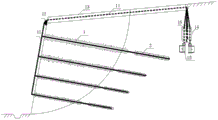
FIG. 1 is a cross-sectional view of a structure of the present invention; FIG. 2 is a structural elevation of the present invention; FIG. 3 is a diagram of the connection and position relationship between the anchor rod and the lifting unloading steel tube according to the present invention; FIG. 4 is a schematic structural diagram of a first type of sleeve A of the present invention; FIG. 5 is a schematic structural view of a second type of sleeve B according to the present invention; FIG. 6 is a schematic view of the construction of the crown block of the present invention; FIG. 7 is a schematic view of the anchor pier of the present invention; FIG. 8 is a schematic view of the cord tensioner of the present invention; FIG. 9 is a schematic view of a fixed steel plate according to the present invention. Description of reference numerals: the concrete anchor comprises a lifting unloading steel pipe 1, an anchor rod 2, an external pull anchor structure 3, a circular steel plate 4, a fixed steel plate 5, a grout outlet 6, a groove 7, a free section 8, an anchoring section 9, a grout stop plug 10, a steel strand 11, a fixed pulley 12, a concrete groove 13, an anchor pier 14, a rope tightener 15, a steel pipe 16, a first sleeve A, a second sleeve B, a first circular hole C and a second circular hole D.
Detailed Description
The invention will now be further described with reference to the accompanying drawings and specific examples, which are given by way of illustration and not by way of limitation. All changes, equivalents and modifications that come within the spirit of the invention are desired to be protected.
As shown in fig. 1 to 9, the present invention provides an in-layer lifting and unloading type anchor rod and a construction method thereof, wherein the in-layer lifting and unloading type anchor rod comprises a lifting and unloading steel pipe 1, an anchor rod 2 and an external pulling anchor structure 3; the lifting unloading steel pipe 1 comprises a first sleeve A, a second sleeve B, an annular steel plate 4 and a fixed steel plate 5, wherein the first sleeve A is a steel pipe with a circular slurry outlet hole 6 in the outer surface, one end of the first sleeve A is provided with a groove 7 which does not penetrate through the thickness of the steel pipe along the circumference, the second sleeve B is provided with no hole along the circumference, the second sleeve B is sleeved into the first sleeve A, the end, which is not provided with the groove 7, of the first sleeve A and the end, which is not provided with the groove 7, of the second sleeve B are vertically welded on the annular steel plate 4, the fixed steel plate 5 is a steel plate with the side length larger than the diameter of the first sleeve A, two first circular holes C and two second circular holes D which do not penetrate through the fixed steel plate 5 and are distributed in different sizes along the center line of the surface, and the first circular; the anchor rod 2 consists of a free section 8, an anchoring section 9 and a grout stop plug 10, wherein the free section 8 of the anchor rod 2 penetrates through the second sleeve B and is fixed at one end, located on the surface of a side slope, of the second sleeve B through an anchor, the anchoring section 9 is arranged in a stable soil layer, and the grout stop plug 10 is sleeved at one end, connected with the free section 8, of the anchoring section 9; the external pull anchor structure 3 is composed of steel strands 11, a fixed pulley 12, a concrete groove 13, anchor piers 14 and a rope tightener 15, wherein the fixed pulley 12 is tightly attached to the surface of a slope and fixed above the first row of anchor rods 2, the concrete groove 13 is formed in the position with the same height as the fixed pulley 12 along the top of the slope, the anchor piers 14 are formed by placing steel pipes 16 in a steel cylinder model at equal intervals along the circumference and grouting and pouring the parts except the steel pipes 16, the anchor piers 14 are embedded in a stable soil layer behind an anchoring section 9 of the anchor rods 2, the opening direction of the steel pipes 16 in the anchor piers 14 is perpendicular to the tail end of the concrete groove 13, the rope tightener 15 is placed at the lower end of the anchor pier 14, one end of each steel strand 11 is connected with a fixed steel plate 5 through a second circular opening D, and the other end of each steel strand 11 upwards passes through the fixed pulley 12, the concrete; one end of the lifting and unloading steel pipe 1 with the circular steel plate 4 is sleeved on the free section 8 of the anchor rod 2 and is arranged in a stable soil layer, and the other end of the lifting and unloading steel pipe is connected with the external pulling anchor structure 3 through a steel strand 11 and is fixed on the outer surface of a side slope (or a foundation pit) to form a layered internal lifting and unloading type ground pulling anchor rod.
As shown in fig. 2, the length of the lifting unloading steel pipe 1 is less than that of the free section 8 of the anchor rod 2, the length of the lifting unloading steel pipe 1 entering a stable soil layer is 0.3-0.5 m, and the distance between the grout stop plug 10 and the lifting unloading steel pipe 1 is 0.3-0.5 m.
As shown in figure 2, the position of the anchor pier 14 on the stabilized soil layer is vertical to the end position of the concrete groove 13, the depth of the concrete groove 13 is 20-40 mm, and the embedding depth of the anchor pier 14 is 1500-2500 mm.
As shown in fig. 1 and 6, the fixed pulley 12 is fixed on the slope surface above the first layer anchor rod 2, and the height of the fixed pulley 12 is 1000-2000 mm, and the diameter is 120-150 mm.
As shown in fig. 4 and 5, the first type casing pipe a and the second type casing pipe B have the same length, the diameter of the first type casing pipe a is larger than that of the second type casing pipe B, the two types of casing pipes are formed by connecting sections, the length of each section of the first type casing pipe a and each section of the second type casing pipe B is 0.8-1.2 m, the diameter of the first type casing pipe a is 120-150 mm, and the diameter of the second type casing pipe B is 90-100 mm; the outer diameter of the circular steel plate 4 is equal to that of the first sleeve A, and the inner diameter of the circular steel plate is equal to that of the second sleeve B.
As shown in figure 4, the grout outlet holes 6 are circular, have the diameter of 8-12 mm and are uniformly arranged along the outer surface of the first-type sleeve A in a quincunx shape.
As shown in FIG. 7, the number of the steel pipes 16 arranged along the circumference of the anchor pier 14 is the same as the number of the layers of the anchor rods 2, and the diameter of each steel pipe 16 is 16-25 mm.
As shown in fig. 8, the rope tighteners 15 are commercially available rope tighteners 15, and the number thereof is equal to that of the anchor rods 2.
As shown in FIG. 9, the diameter of the first circular opening C is 120-150 mm, which is the same as that of the first sleeve A, and the diameter of the second circular opening D is 22-30 mm, which is larger than that of the steel strand 11.
The invention relates to a construction method of a layered lifting and unloading type ground pulling anchor rod, which adopts a reverse construction method and layered construction in the construction sequence and comprises the following steps:
(1) manufacturing a lifting unloading steel pipe 1: determining the size and the number of the lifting unloading steel pipes 1 according to engineering design requirements; prefabricating a first-type sleeve A, a second-type sleeve B, a circular steel plate 4 and a fixed steel plate 5, forming a circular slurry outlet hole 6 in the outer surface of the first-type sleeve A, forming a groove 7 at one end of the first-type sleeve A, vertically welding the circular steel plate 4 to one end of the first-type sleeve A, which is not provided with the groove 7, and embedding the fixed steel plate 5 on the groove 7 of the first-type sleeve A;
(2) manufacturing an external pull anchor structure 3: determining the sizes and the number of the steel strands 11, the fixed pulleys 12, the anchor piers 14 and the rope tighteners 15 according to engineering design requirements, manufacturing the fixed pulleys 12 matched with the steel strands 11, placing steel pipes 16 in a steel cylinder model at equal intervals along the circumference, and grouting and pouring parts except the steel pipes 16 to form the anchor piers 14;
(3) positioning and drilling: according to the engineering design requirement, measuring the construction position of the positioning anchor rod 2 by using an instrument, and drilling by using a drilling instrument, wherein the diameter of the drilled hole is equal to that of the first-type sleeve A;
(4) and (3) constructing an external pull anchor structure: placing the lifting unloading steel pipe 1 into a drill hole and grouting in an interlayer formed between the two types of sleeves; sleeving a first circular opening C of a fixed steel plate 5 on a groove 7 of a first sleeve A, fixing a fixed pulley 12 above a first row of anchor rods 2 by clinging to the surface of a slope, arranging a concrete groove 13 at a position with the same height as the fixed pulley 12 along the top of the slope, wherein the length of the concrete groove 13 is greater than that of the anchor rods 2, and vertically embedding an anchor pier 14 in a stable soil layer to ensure that the anchor pier is perpendicular to the tail end of the concrete groove 13;
(5) and (3) constructing an anchor rod 2: putting an anchor rod 2 through the lifting unloading steel pipe 1 into the positioning drill hole, grouting the anchoring section 9, when the strength of the grouting body reaches the designed strength, enabling one end of a steel strand 11 to pass through the second round opening D and pulling the other end of the steel strand upwards along the surface of the slope, enabling the steel strand to sequentially pass through a fixed pulley 12, a concrete groove 13 and an anchor pier 14 and be connected with a rope tightener 15, and rotating the rope tightener 15 to tighten the steel strand 11;
(6) and (5) constructing other anchor rods 2 in sequence according to the steps (4) and (5).
The working principle of the layered lifting unloading type ground pulling anchor rod provided by the invention is as follows: (1) the anchoring principle is as follows: the anchor rod is inserted into the side slope drilling hole and grouted to enable the anchor rod to be stabilized in the soil body, and the anchor rod in the side slope is applied with tensioning prestress to generate anchoring force so as to anchor the soil body in the side slope sliding area in the stabilizing area. (2) The reinforcement principle is as follows: grouting into the lifting and unloading steel pipe, wherein the slurry flows into the surrounding soil body through the slurry outlet hole, so that the surrounding soil body is reinforced by the slurry, and a reinforced concrete reinforcing area with the diameter larger than that of the lifting and unloading steel pipe is formed; meanwhile, after the free section of the anchor rod penetrates through the lifting unloading steel pipe, the free section of the anchor rod can not only resist tension but also resist bending and compression, and fully participates in the work of reinforcing the soil body. (3) The unloading principle is as follows: one end of the lifting unloading steel pipe is fixed in a stable soil layer, the other end of the lifting unloading steel pipe is fixed on the surface of a slope through the pulling force of a steel strand and a rope tightener in an external pulling anchor structure, grouting is carried out in a pipeline formed between a first sleeve A and a second sleeve B of the lifting unloading steel pipe, slurry flows into soil around the sleeves through a grout outlet hole and is fused with soil to form a steel pipe concrete grouting reinforcement area, and the grouting reinforcement area bears the soil pressure transmitted by the upper soil, so that the soil pressure acting on a lower structure is reduced, and the unloading effect is achieved; by analogy, each section of lifting unloading steel pipe bears the soil pressure at the upper part, so that the soil pressure acting on the lower-layer anchor rod is gradually reduced, the length of the anchor rod is further reduced, and materials are saved.
Claims (7)
1. An in-layer lifting unloading type ground anchor rod comprises a lifting unloading steel pipe (1), an anchor rod (2) and an outer pull anchor structure (3); the method is characterized in that: the lifting unloading steel pipe (1) consists of a first sleeve (A), a second sleeve (B), a circular steel plate (4) and a fixed steel plate (5), the first sleeve (A) is a steel pipe with a circular grout outlet (6) on the outer surface, one end of the sleeve is provided with a groove (7) which does not penetrate through the thickness of the steel pipe along the circumference, the second sleeve (B) has no hole on the whole body, the second sleeve (B) is sleeved in the first sleeve (A), one end of the first sleeve (A) without the groove (7) and one end of the second sleeve (B) are vertically welded on the circular steel plate (4), the fixed steel plate (5) is a steel plate with the side length larger than the diameter of the first sleeve (A), the surface of the steel plate is provided with a first round hole (C) and a second round hole (D) which are distributed in different sizes up and down along the central line and do not penetrate through the fixed steel plate (5), and the first round hole (C) is embedded in the groove (7); the anchor rod (2) is composed of a free section (8), an anchoring section (9) and a grout stop plug (10), the free section (8) of the anchor rod (2) penetrates through the second sleeve (B) and is fixed at one end, located on the surface of a side slope, of the second sleeve (B) through an anchor, the anchoring section (9) is placed in a stable soil layer, and the grout stop plug (10) is sleeved at one end, connected with the free section (8), of the anchoring section (9); the external-pulling anchor structure (3) is composed of a steel strand (11), a fixed pulley (12), a concrete groove (13), an anchor pier (14) and a rope tightener (15), wherein the fixed pulley (12) is tightly attached to the surface of a slope and fixed above a first row of anchor rods (2), the concrete groove (13) is formed in the position with the same height as the fixed pulley (12) along the top of the slope, the anchor pier (14) is formed by placing steel pipes (16) in a steel cylinder model at equal intervals along the circumference and grouting and pouring the parts outside the steel pipes (16), the anchor pier (14) is embedded in a stable soil layer behind an anchoring section (9) of the anchor rod (2), the opening direction of the steel pipes (16) in the anchor pier (14) is perpendicular to the tail end of the concrete groove (13), the rope tightener (15) is placed at the lower end of the anchor pier (14), one end of the steel strand (11) is connected with a fixed steel plate (5) through a second circular opening (D), and the other end of the steel strand (11) sequentially passes, The concrete groove (13) and the anchor pier (14) are connected with the rope tightener (15); one end of the lifting unloading steel pipe (1) with the circular steel plate (4) is sleeved on the free section (8) of the anchor rod (2) and is arranged in a stable soil layer, and the other end of the lifting unloading steel pipe is connected with the outer pulling anchor structure (3) through a steel strand (11) and is fixed on the outer surface of a side slope or a foundation pit to form a layered inner lifting unloading type ground pulling anchor rod.
2. The tiered inner lift unload type floor tie anchor of claim 1 wherein: the length of the lifting unloading steel pipe (1) entering the stable soil layer is 0.3-0.5 m; the length of the lifting unloading steel pipe (1) is less than the length of the free section (8) of the anchor rod (2) entering a stable soil layer from the surface of the side slope; and a space is reserved between the tail end of the lifting unloading steel pipe (1) and the grout stop plug (10) of the anchor rod (2).
3. The tiered inner lift unload type floor tie anchor of claim 1 wherein: the length of the first sleeve (A) is the same as that of the second sleeve (B), the diameter of the first sleeve (A) is larger than that of the second sleeve (B), and the first sleeve (A) and the second sleeve (B) are formed by connecting in sections; the outer diameter of the circular steel plate (4) is equal to that of the first sleeve (A), and the inner diameter of the circular steel plate is equal to that of the second sleeve (B).
4. The tiered inner lift unload type floor tie anchor of claim 1 wherein: the diameter of the first circular opening (C) is equal to that of the first sleeve (A), and the diameter of the second circular opening (D) is larger than that of the steel strand (11).
5. The tiered inner lift unload type floor tie anchor of claim 1 wherein: the grout outlet holes (6) are circular, have the diameter of 8-12 mm and are uniformly arranged along the outer surface of the first-type sleeve (A) in a quincunx shape.
6. The tiered inner lift unload type floor tie anchor of claim 1 wherein: in the external pull anchor structure (3), the fixed pulleys (12) and the anchor rods (2) are in the same row number, and the fixed pulleys (12) are positioned below the ground surface and above the first layer of anchor rods (2); the height of the steel pipe (16) is the same as that of a steel cylinder model for pouring the anchor pier (14), and the number of the steel pipes (16) arranged along the circumference of the anchor pier (14) is the same as the number of the anchor rods (2); the number of the rope tighteners (15) is equal to that of the anchor rods (2).
7. A construction method of an in-layer lifting and unloading type ground pulling anchor rod is characterized by comprising the following construction steps:
(1) manufacturing a lifting unloading steel pipe (1): determining the size and the number of the lifting unloading steel pipes (1) according to engineering design requirements; prefabricating a first-type sleeve (A), a second-type sleeve (B), a circular steel plate (4) and a fixed steel plate (5), forming a circular slurry outlet hole (6) in the outer surface of the first-type sleeve (A), forming a groove (7) in one end of the first-type sleeve, vertically welding the circular steel plate (4) to one end of the first-type sleeve (A) which is not provided with the groove (7) and one end of the second-type sleeve (B) for connection, and embedding the fixed steel plate (5) on the groove (7) of the first-type sleeve (A);
(2) manufacturing an external pull anchor structure (3): determining the sizes and the number of the required steel strand (11), the fixed pulley (12), the anchor pier (14) and the rope tightener (15) according to engineering design requirements, manufacturing the fixed pulley (12) matched with the steel strand (11), placing steel pipes (16) in a steel cylinder model at equal intervals along the circumference, and grouting and pouring the parts except the steel pipes (16) to form the anchor pier (14);
(3) positioning and drilling: according to the engineering design requirement, measuring the construction position of the positioning anchor rod (2) by using an instrument, and drilling by using a drilling instrument, wherein the diameter of the drilled hole is equal to that of the first-type sleeve (A);
(4) constructing an external pulling anchor structure (3): placing the lifting unloading steel pipe (1) into a drill hole and grouting in an interlayer formed between the two types of sleeves; sleeving a first circular opening (C) of a fixed steel plate (5) on a groove (7) of a first sleeve (A), fixing a fixed pulley (12) above a first row of anchor rods (2) in a manner of clinging to the surface of a slope, forming a concrete groove (13) at a position with the same height as the fixed pulley (12) along the top of the slope, wherein the length of the concrete groove (13) is greater than that of the anchor rods (2), and vertically embedding an anchor pier (14) in a stable soil layer to enable the anchor pier to be perpendicular to the tail end of the concrete groove (13);
(5) construction anchor rod (2): putting an anchor rod (2) into a positioning drill hole after penetrating through a lifting unloading steel pipe (1), grouting an anchoring section (9), when the strength of a grouting body reaches a designed strength, enabling one end of a steel strand (11) to penetrate through a second round opening (D) and the other end of the steel strand to be pulled upwards along the surface of a side slope, enabling the steel strand to sequentially pass through a fixed pulley (12), a concrete groove (13) and an anchor pier (14) and be connected with a rope tightener (15), and rotating the rope tightener (15) to tighten the steel strand (11);
(6) and (5) constructing other anchor rods (2) in sequence according to the steps (4) and (5).
Priority Applications (1)
| Application Number | Priority Date | Filing Date | Title |
|---|---|---|---|
| CN201810713857.6A CN108842792B (en) | 2018-07-03 | 2018-07-03 | Layered lifting and unloading type ground pulling anchor rod and construction method |
Applications Claiming Priority (1)
| Application Number | Priority Date | Filing Date | Title |
|---|---|---|---|
| CN201810713857.6A CN108842792B (en) | 2018-07-03 | 2018-07-03 | Layered lifting and unloading type ground pulling anchor rod and construction method |
Publications (2)
| Publication Number | Publication Date |
|---|---|
| CN108842792A CN108842792A (en) | 2018-11-20 |
| CN108842792B true CN108842792B (en) | 2020-04-07 |
Family
ID=64201207
Family Applications (1)
| Application Number | Title | Priority Date | Filing Date |
|---|---|---|---|
| CN201810713857.6A Active CN108842792B (en) | 2018-07-03 | 2018-07-03 | Layered lifting and unloading type ground pulling anchor rod and construction method |
Country Status (1)
| Country | Link |
|---|---|
| CN (1) | CN108842792B (en) |
Families Citing this family (3)
| Publication number | Priority date | Publication date | Assignee | Title |
|---|---|---|---|---|
| CN110512612A (en) * | 2019-06-03 | 2019-11-29 | 中国建筑股份有限公司 | A kind of equilibrium multi beam prestress anchorage cable connecting structure and its construction method certainly |
| CN113005991A (en) * | 2021-03-08 | 2021-06-22 | 广东浩禹建设有限公司 | High-strength anti-seismic water conservancy slope anchor cable structure |
| CN114032721B (en) * | 2021-11-29 | 2022-12-27 | 杭州光华路桥工程有限公司 | Asphalt pavement composite structure and construction method thereof |
Citations (4)
| Publication number | Priority date | Publication date | Assignee | Title |
|---|---|---|---|---|
| JPH08105053A (en) * | 1994-10-06 | 1996-04-23 | Sumikin Kozai Kogyo Kk | Slope protection construction method |
| CN1469017A (en) * | 2002-07-16 | 2004-01-21 | 石午江 | High slope rock and soil anchoring construction method and apparatus |
| CN203781713U (en) * | 2014-01-21 | 2014-08-20 | 陕西天地地质有限责任公司 | High slope support material transport device |
| CN104153376A (en) * | 2013-05-15 | 2014-11-19 | 青岛天力建筑加固工程有限公司 | Balance weight type slope protector |
-
2018
- 2018-07-03 CN CN201810713857.6A patent/CN108842792B/en active Active
Patent Citations (4)
| Publication number | Priority date | Publication date | Assignee | Title |
|---|---|---|---|---|
| JPH08105053A (en) * | 1994-10-06 | 1996-04-23 | Sumikin Kozai Kogyo Kk | Slope protection construction method |
| CN1469017A (en) * | 2002-07-16 | 2004-01-21 | 石午江 | High slope rock and soil anchoring construction method and apparatus |
| CN104153376A (en) * | 2013-05-15 | 2014-11-19 | 青岛天力建筑加固工程有限公司 | Balance weight type slope protector |
| CN203781713U (en) * | 2014-01-21 | 2014-08-20 | 陕西天地地质有限责任公司 | High slope support material transport device |
Also Published As
| Publication number | Publication date |
|---|---|
| CN108842792A (en) | 2018-11-20 |
Similar Documents
| Publication | Publication Date | Title |
|---|---|---|
| CN106320346B (en) | Campshed adds anchor cable grouting behind shaft or drift lining deep foundation pit supporting construction method | |
| CN201722685U (en) | No-adhesive prestress and pile side rear grouting punching pile structure | |
| CN108842792B (en) | Layered lifting and unloading type ground pulling anchor rod and construction method | |
| CN105951826A (en) | Suction ground anchor device in tubular pile and water pressure injection method thereof | |
| CN109024721B (en) | Reinforced foundation and method for improving bending and shearing resistance of existing building rigid foundation | |
| CN106968245A (en) | The uplift pile of prestress anchorage cable manually digging hole and its construction method | |
| CN106638655A (en) | Conical-head tendon body post-tensioning pile foundation and construction process thereof | |
| CN110206071B (en) | Method and device for reinforcing joints of underground continuous wall | |
| CN103410144B (en) | Prestressed reinforcement piles set into rock and construction method | |
| CN210263075U (en) | Arrange bars formula tubular pile post back slip casting internal anchor outer stagnant water support system | |
| CN107542086B (en) | Anchor cable construction method for filling slope | |
| CN203361150U (en) | Composite anti-floating anchor pile | |
| CN110219300B (en) | Construction process of partially-bonded prestressed uplift anchor rod | |
| CN217378870U (en) | Major diameter prestressed steel pipe concrete friction pile | |
| CN107447775A (en) | Landslide disaster body makes ground draining reinforced earth retaining wall structure | |
| CN113005991A (en) | High-strength anti-seismic water conservancy slope anchor cable structure | |
| CN108301400B (en) | Hollow drainage anchoring anti-slide pile and construction method thereof | |
| CN205677538U (en) | A kind of anchor bit of Recyclable anchor rope | |
| CN115030155B (en) | Construction method of photovoltaic support precast pile for harder stratum based on grouting process | |
| CN218027734U (en) | Embedded type isolation pile embedded into grouting pipe | |
| CN211547736U (en) | Grouting system of ultra-deep foundation pit | |
| CN214695767U (en) | It passes through building foundation connection structure earlier to establish prestressed anchorage pole earlier | |
| CN212670663U (en) | Partial-bonding prestress anti-pulling anchor steel strand cage with bearing plate and anti-pulling anchor | |
| CN212956513U (en) | Precast concrete block for hole digging pile retaining wall and manual hole digging pile retaining wall mounting structure | |
| CN204000837U (en) | A kind of prefabricated diaphragm wall |
Legal Events
| Date | Code | Title | Description |
|---|---|---|---|
| PB01 | Publication | ||
| PB01 | Publication | ||
| SE01 | Entry into force of request for substantive examination | ||
| SE01 | Entry into force of request for substantive examination | ||
| GR01 | Patent grant | ||
| GR01 | Patent grant |