CN111508697B - Terminal and magnetic core kludge - Google Patents
Terminal and magnetic core kludge Download PDFInfo
- Publication number
- CN111508697B CN111508697B CN202010604134.XA CN202010604134A CN111508697B CN 111508697 B CN111508697 B CN 111508697B CN 202010604134 A CN202010604134 A CN 202010604134A CN 111508697 B CN111508697 B CN 111508697B
- Authority
- CN
- China
- Prior art keywords
- assembling
- guide rail
- rubberizing
- electric guide
- translation
- Prior art date
- Legal status (The legal status is an assumption and is not a legal conclusion. Google has not performed a legal analysis and makes no representation as to the accuracy of the status listed.)
- Active
Links
Images


Classifications
-
- H—ELECTRICITY
- H01—ELECTRIC ELEMENTS
- H01F—MAGNETS; INDUCTANCES; TRANSFORMERS; SELECTION OF MATERIALS FOR THEIR MAGNETIC PROPERTIES
- H01F41/00—Apparatus or processes specially adapted for manufacturing or assembling magnets, inductances or transformers; Apparatus or processes specially adapted for manufacturing materials characterised by their magnetic properties
Landscapes
- Engineering & Computer Science (AREA)
- Power Engineering (AREA)
- Manufacturing & Machinery (AREA)
- Manufacture Of Motors, Generators (AREA)
Abstract
The invention discloses a terminal and magnetic core assembling machine, which comprises a frame, wherein a conveying mechanism is arranged on the frame, a first conveying space and a second conveying space of the conveying mechanism are arranged on the frame, the second conveying space is positioned on the right side relative to the first conveying space, a gluing mechanism, a feeding mechanism, a first assembling mechanism, a first disassembling mechanism, a second assembling mechanism, a second disassembling mechanism, a discharging mechanism and a transferring mechanism are also arranged on the frame, the gluing mechanism, the first assembling mechanism, the first disassembling mechanism, the second assembling mechanism, the second disassembling mechanism and the discharging mechanism are sequentially arranged along the direction from the first conveying space to the second conveying space, the feeding mechanism is positioned beside the first assembling mechanism, and the transferring mechanism is positioned between the first disassembling mechanism and the second assembling mechanism. The economic benefit is improved.
Description
Technical Field
The invention relates to mechanical equipment, in particular to a terminal and magnetic core assembling machine.
Background
When assembling the coil, need assemble terminal and magnetic core, traditional packaging method is manual operation, the workman need take out the terminal of arranging on the carrier band earlier, then point glue on the terminal, the both sides of magnetic core are adorned respectively with two terminals again, whole assembling process is though simple, but workman's operation appears like glue point dislocation very easily, the glue volume is not good, pressing force degree is improper when terminal and magnetic core are assembled and lead to assembling unstability or press bad product scheduling problem, the quality of equipment is difficult to handle the accuse, and packaging efficiency is difficult to improve.
Disclosure of Invention
The present invention is directed to a terminal and magnetic core assembling machine, which solves one or more of the problems of the prior art and provides at least one of the advantages of the present invention.
The solution of the invention for solving the technical problem is as follows:
the utility model provides a terminal and magnetic core kludge, includes the frame, be provided with conveying mechanism in the frame, conveying mechanism has first transport space and second transport space, with the second transport space is relative the position that first transport space locates is relative right direction, still be provided with rubberizing mechanism, feed mechanism, first assembly device, first disassembly body, second assembly device, second disassembly body, unloading mechanism, transfer mechanism in the frame, rubberizing mechanism, first assembly device, first disassembly body, second assembly device, second disassembly body, unloading mechanism follow first transport space extremely the direction in second transport space is arranged in proper order, feed mechanism is located the side of first assembly device, transfer mechanism is located between first disassembly body and the second assembly device.
The technical scheme at least has the following beneficial effects: the machine frame is provided with a conveying mechanism for conveying an external carrier tape, terminals are uniformly arranged on the carrier tape, the carrier tape is conveyed from a first conveying space to a second conveying space, the terminals on the carrier tape sequentially pass through the processes of gluing, first assembling, first disassembling, second assembling, second disassembling and blanking in the conveying process, specifically, the gluing mechanism is used for gluing the terminals on the carrier tape, the feeding mechanism is used for feeding magnetic cores, then the first assembling mechanism is used for assembling one side of the magnetic cores and the terminals on the carrier tape, the magnetic cores and the terminals are positioned on the carrier tape at the moment, the magnetic cores assembled on the terminals are taken out from the carrier tape by the first disassembling mechanism, the terminals and the magnetic cores are transferred to the second assembling mechanism by the transferring mechanism, the other side of the magnetic cores and the terminals on the carrier tape are assembled by the second assembling mechanism, and finally the whole body is disassembled from the carrier tape by the second disassembling mechanism, the blanking mechanism is used for blanking and collecting, so that the whole assembling process is completed, the whole process is automatically completed by machinery, manual operation is reduced, the stability of mechanical operation in each process is higher, the assembling quality is ensured while the assembling efficiency is improved, and the economic benefit is improved.
As a further improvement of the above technical solution, the conveying mechanism includes a reel rotatably connected to the frame and a first driving motor, the first driving motor can drive the reel to rotate, a conveying base and a supporting frame are disposed on the top surface of the frame, the conveying base is rotatably connected to a first conveying wheel and a second conveying wheel, the rotation axis of the reel, the rotation axis of the first conveying wheel and the rotation axis of the second conveying wheel all extend in the front-rear direction, a first clearance groove is disposed on the peripheral wall of the first conveying wheel, the first conveying wheel and the second conveying wheel are spaced in the up-down direction, a first conveying space is formed between the first conveying wheel and the second conveying wheel, a third conveying wheel and a fourth conveying wheel are rotatably connected to the supporting frame, a second driving motor is disposed on the supporting frame, and the second driving motor can drive the third conveying wheel to rotate, the periphery wall of fourth delivery wheel is provided with the fourth and keeps away empty groove, the third delivery wheel with the fourth delivery wheel sets up along preceding rear direction interval, the axis of rotation of third delivery wheel with the axis of rotation of fourth delivery wheel all extends along upper and lower direction, the third delivery wheel with form between the fourth delivery wheel the second is carried the space. The reel is wound with a peripheral carrier tape to be loaded, the first driving motor drives the reel to rotate, the carrier tape is discharged, one end of the discharged carrier tape is clamped in the first conveying space to be positioned and then clamped in the second conveying space, the second driving motor and the first driving motor synchronously rotate, the carrier tape is pulled, the carrier tape is continuously discharged from the reel and straightened in the first conveying space and the second conveying space, terminals are distributed on the carrier tape, and can interfere with the conveying wheels when passing through the first conveying space and the second conveying space, so that a first clearance groove is formed in the first conveying wheel, a fourth clearance groove is formed in the fourth conveying wheel and used for avoiding the terminals, and the carrier tape can be stably conveyed.
As a further improvement of the above technical scheme, the gluing mechanism comprises a gluing seat, a gluing translation cylinder, a gluing translation plate, a gluing lifting cylinder, a glue dispensing head, a gluing driving motor and a gluing tray, wherein the gluing seat is fixedly connected to the frame, a limiting channel extends in the gluing seat along the left and right directions, a gluing hole communicated with the limiting channel is formed in the top surface of the gluing seat, the gluing driving motor is connected to the frame and can drive the gluing tray to rotate, the gluing tray is positioned behind the gluing seat, the rotation axis of the gluing tray extends along the vertical direction, the gluing translation cylinder is connected to the frame and is positioned in front of the gluing seat, the gluing translation plate is arranged on the gluing translation cylinder, and the gluing translation cylinder can drive the gluing translation plate to move back and forth between the gluing tray and the gluing hole, the rubberizing lift cylinder connect in on the rubberizing translation board, the head of dispensing set up in on the rubberizing lift cylinder, rubberizing lift cylinder can drive the head of dispensing is along being close to or keeping away from the direction motion in rubberizing hole. The carrier band passes spacing passageway, and the rubberizing head can make translation, elevating movement respectively under the drive of rubberizing translation cylinder, rubberizing lift cylinder, and the rubberizing head can be followed the rubberizing hole with the glue that holds in the rubberizing dish and glued the carrier band on so, and rubberizing driving motor can make the rubberizing dish rotate to make the glue in the rubberizing dish flow more evenly.
As the further improvement of above-mentioned technical scheme, feed mechanism includes the vibration dish and directly shakes the guide slot, the vibration dish has the discharge gate, directly shake the guide slot one end connect in the discharge gate, directly shake the other end of guide slot and be the discharge end, the discharge end is located on the support frame, it is connected with first leading wheel and second leading wheel to rotate on the support frame, the rotation axis of first leading wheel with the rotation axis of second leading wheel extends along vertical direction, the periphery wall of second leading wheel is provided with the second and keeps away the dead slot, first leading wheel with the second leading wheel sets up along preceding rear direction interval, first leading wheel with form the guide clearance between the second leading wheel. The vibration disc is used for feeding the magnetic cores from the discharge port to the direct vibration guide groove, the magnetic cores are arranged in the direct vibration guide groove along the linear direction and are discharged from the discharge end one by one, the guide gap formed by the first guide wheel and the second guide wheel on the support frame can be used for steering the carrier tape sent out from the first conveying space, the carrier tape is enabled to rotate to the vertical state from the horizontal state, the subsequent process operation is facilitated, and similarly, the first empty avoiding groove and the second empty avoiding groove provide an avoiding space for the terminal and the carrier tape can stably pass through the guide gap.
As a further improvement of the above technical solution, the first assembling mechanism includes a first assembling table, a first assembling electric guide rail, a first pushing plate, a first assembling translation cylinder, a first translation plate, a first positioning pin and a second positioning pin, the first assembling electric guide rail, the first assembling table, the first assembling translation cylinder are sequentially arranged on the supporting frame along the front-back direction, a first left limiting block and a first right limiting block are arranged on the top surface of the first assembling table, the first left limiting block and the first right limiting block are arranged along the left-right direction at an interval, a first limiting space is formed between the first left limiting block and the first right limiting block, the first pushing plate is arranged on the first assembling electric guide rail, the first assembling electric guide rail can drive the first pushing plate to approach to or leave from the first limiting space, the first translation plate is arranged on the first assembling translation cylinder, first assembly translation cylinder can drive first translation board is along the fore-and-aft direction motion, first locating pin, second locating pin fixed connection in on the first translation board, first locating pin is kept away from the one end of first translation board is just to first left stopper, the second locating pin is kept away from the one end of first translation board is just to first right stopper. Magnetic core material loading to first assembly bench, the carrier band that has the terminal passes through between first assembly translation cylinder and the first assembly bench, during the assembly, utilize first assembly translation cylinder to put and drive the translation board and be close to first assembly bench for first locating pin compresses tightly the carrier band on first assembly bench with the second locating pin, then utilize first assembly electronic guide rail to drive push plate and be close to spacing space, make push plate push the magnetic core on the first assembly bench to spacing space, and press on the terminal, can accomplish the assembly of terminal and magnetic core.
As a further improvement of the technical proposal, the first disassembling mechanism comprises a first disassembling platform, a first disassembling electric guide rail, a first pushing rod, a second disassembling electric guide rail and a second pushing rod, the first dismounting electric guide rail, the first dismounting table and the second dismounting electric guide rail are arranged on the supporting frame in sequence along the front-back direction, the top surface of the first disassembling platform is provided with a first limit through groove in an extending way along the front-back direction, the first pushing rod is arranged on the first disassembling electric guide rail, the first dismounting electric guide rail can drive the first pushing rod to move back and forth in the first limiting through groove, the second pushing rod is arranged on the second disassembly electric guide rail, one end of the second pushing rod is opposite to the first pushing rod, the second detachable electric guide rail can drive the second pushing rod to move along the direction close to or far away from the first limiting through groove. The carrier band is between first dismantlement platform and the second propelling movement pole, utilize first electronic guide rail of dismantlement to drive first propelling movement pole and pass first spacing logical groove, and with first propelling movement pole and the terminal of equipment together offset with the magnetic core, utilize the electronic guide rail of second dismantlement simultaneously to drive the second propelling movement pole and be close to first dismantlement platform, make second propelling movement pole and terminal and the assembly of magnetic core equipment to the combination body together offset, then first propelling movement pole and second propelling movement pole are pressed from both sides the combination body and are transferred to first spacing logical groove department, can tear the terminal from the carrier band this moment, so can accomplish to dismantle the terminal that will assemble with the magnetic core from the carrier band and go out.
As a further improvement of the above technical solution, the second assembling mechanism includes a second assembling table, a second assembling electric guide rail, a third pushing rod, a second assembling translation cylinder, a second translation plate, a third positioning pin and a fourth positioning pin, the second assembling electric guide rail, the second assembling table and the second assembling translation cylinder are sequentially arranged on the supporting frame along the front-back direction, a second left limiting block and a second right limiting block are arranged on the top surface of the second assembling table, the second left limiting block and the second right limiting block are arranged at an interval along the left-right direction, a second limiting space is formed between the second left limiting block and the second right limiting block, the third pushing rod is arranged on the second assembling electric guide rail, the second assembling electric guide rail can drive the third pushing rod to approach or leave the second limiting space, the second translation plate is arranged on the second assembling translation cylinder, the second assembling translation cylinder can drive the second translation plate to move in the front-back direction, the third positioning pin and the fourth positioning pin are fixedly connected to the second translation plate, one end, far away from the second translation plate, of the third positioning pin is right opposite to the second left limiting block, and one end, far away from the second translation plate, of the fourth positioning pin is right opposite to the second right limiting block. The magnetic core that one side was equipped with the terminal is transferred to the second assembly bench, the carrier band that has the terminal passes through between second assembly translation cylinder and the second assembly bench, during the assembly, utilize second assembly translation cylinder to put and drive the second translation board and be close to the second assembly bench, make third locating pin and fourth locating pin compress tightly the carrier band on the second assembly bench, then utilize second assembly electric guide rail to drive third propelling movement pole and be close to the spacing space of second, make the third propelling movement pole push the magnetic core on the second assembly bench to the spacing space of second, and press on the terminal, can assemble the terminal to another lateral wall of magnetic core.
As a further improvement of the above technical solution, the second dismounting mechanism includes a second dismounting platform, a third dismounting electric guide rail, a fourth pushing rod, a fifth pushing rod, a fourth dismounting electric guide rail, a sixth pushing rod, and a seventh pushing rod, the third dismounting electric guide rail, the second dismounting platform, and the fourth dismounting electric guide rail are sequentially arranged on the support frame along the front-back direction, the top surface of the second dismounting platform is provided with a second limiting through groove and a third limiting through groove at intervals along the left-right direction, the second limiting through groove and the third limiting through groove both extend along the front-back direction, the fourth pushing rod and the fifth pushing rod are disposed on the third dismounting electric guide rail, the third dismounting electric guide rail can drive the fourth pushing rod and the fifth pushing rod to respectively move back and forth in the second limiting through groove and the third limiting through groove, the sixth pushing rod and the seventh pushing rod are disposed on the fourth dismounting electric guide rail, one end of the sixth pushing rod faces the fourth pushing rod, one end of the seventh pushing rod faces the fifth pushing rod, and the fourth dismounting electric guide rail can drive the fifth pushing rod and the seventh pushing rod to move along the directions close to or far away from the second limiting through groove and the third limiting through groove respectively. In order to improve the production rhythm, two assembled products are disassembled by utilizing two groups of pushing rods at a time, namely, the fourth pushing rod and the sixth pushing rod form a group together, the fifth pushing rod and the seventh pushing rod form a group together, and the two groups of pushing rods can pull out the assembled products on the carrier tape to the second limiting through groove and the third limiting through groove to finish the disassembly of the products from the carrier tape.
As a further improvement of the above technical solution, the blanking mechanism includes a blanking frame, a gantry, a blanking electric guide rail, a blanking translational plate, a blanking lifting cylinder, and a blanking pneumatic finger, the blanking frame is connected to the gantry, the blanking electric guide rail is connected to the gantry, the blanking translational plate is disposed on the blanking electric guide rail, the blanking electric guide rail can drive the blanking translational plate to move back and forth between the second dismounting mechanism and the blanking frame, the blanking lifting cylinder is connected to the blanking translational plate, the blanking pneumatic finger is disposed on the blanking lifting cylinder, and the blanking lifting cylinder can drive the blanking pneumatic finger to move along the vertical direction. The pneumatic fingers for blanking can be driven by the electric guide rails for blanking and the blanking lifting cylinder to do translation and lifting motion respectively, and can clamp products in the second limiting through groove and the third limiting through groove into the blanking frame to complete the collection and blanking of the products.
As a further improvement of the technical proposal, the transfer mechanism comprises a transfer electric guide rail, a transfer plate, a transfer lifting cylinder, a transfer driving motor and a transfer pneumatic finger, the transfer electric guide rail is connected to the portal frame, the transfer plate is connected to the transfer electric guide rail, the transfer electric guide rail can drive the transfer plate to move back and forth between the first disassembling mechanism and the second assembling mechanism, the transfer lifting cylinder is connected to the transfer plate, the transfer driving motor is arranged on the transfer lifting cylinder, the transfer lifting cylinder can drive the transfer driving motor to move along the vertical direction, the transfer pneumatic finger is arranged on the transfer driving motor, the transfer driving motor can drive the transfer pneumatic finger to rotate, and the rotation axis of the transfer pneumatic finger extends along the vertical direction. The pneumatic finger is transferred to move the electric guide rail and the lifting cylinder to move horizontally and vertically, the workpiece detached from the first limiting through groove is transferred to the second limiting space by the pneumatic finger, and the pneumatic finger is transferred to rotate the pneumatic finger by 180 degrees in the transferring process, so that the terminal is mounted on the other side of the magnetic core.
Drawings
In order to more clearly illustrate the technical solution in the embodiments of the present invention, the drawings used in the description of the embodiments will be briefly described below. It is clear that the described figures are only some embodiments of the invention, not all embodiments, and that a person skilled in the art can also derive other designs and figures from them without inventive effort.
FIG. 1 is an overall perspective view of the present invention;
FIG. 2 is a perspective view of the delivery mechanism of the present invention;
FIG. 3 is a perspective view of the glue application mechanism of the present invention;
FIG. 4 is a perspective view of the feed mechanism of the present invention;
FIG. 5 is a top view of the first assembly mechanism of the present invention;
FIG. 6 is a top plan view of the first detachment mechanism of the present invention;
FIG. 7 is a top view of a second assembly mechanism of the present invention;
FIG. 8 is a top plan view of a second detachment mechanism of the present invention;
fig. 9 is a perspective view of the blanking mechanism and the transfer mechanism of the present invention.
In the drawings: 100-frame, 110-support frame, 200-conveying mechanism, 210-reel, 220-first driving motor, 230-conveying seat, 240-first conveying wheel, 250-second conveying wheel, 260-third conveying wheel, 270-fourth conveying wheel, 280-second driving motor, 300-gluing mechanism, 310-gluing seat, 320-gluing translation cylinder, 330-gluing lifting cylinder, 340-glue dispensing head, 350-gluing driving motor, 360-gluing disk, 400-feeding mechanism, 410-vibrating disk, 420-direct vibration guide groove, 430-first guide wheel, 440-second guide wheel, 500-first assembling mechanism, 510-first assembling table, 520-first assembling electric guide rail, 530-first pushing plate, 540-first assembling translation cylinder, 551-first positioning pin, 552-second positioning pin, 600-first disassembling mechanism, 610-first disassembling table, 620-first disassembling electric guide rail, 630-first pushing rod, 640-second disassembling electric guide rail, 650-second pushing rod, 700-second assembling mechanism, 710-second assembling table, 720-second assembling electric guide rail, 730-third pushing rod, 740-second assembling translation cylinder, 751-third positioning pin, 752-fourth positioning pin, 800-second disassembling mechanism, 810-second disassembling table, 820-third disassembling electric guide rail, 830-fourth pushing rod, 840-fifth pushing rod, 850-fourth disassembling electric guide rail, 860-sixth pushing rod, 870-seventh pushing rod, 910-blanking mechanism, 911-blanking frame, 912-portal frame, 913-blanking electric guide rail, 914-blanking lifting cylinder, 915-blanking pneumatic finger, 920-transfer mechanism, 921-transfer electric guide rail, 922-transfer lifting cylinder, 923-transfer drive motor and 924-transfer pneumatic finger.
Detailed Description
The conception, the specific structure, and the technical effects produced by the present invention will be clearly and completely described below in conjunction with the embodiments and the accompanying drawings to fully understand the objects, the features, and the effects of the present invention. It is obvious that the described embodiments are only a part of the embodiments of the present invention, and not all embodiments, and those skilled in the art can obtain other embodiments without inventive effort based on the embodiments of the present invention, and all embodiments are within the protection scope of the present invention. In addition, all the connection relations mentioned herein do not mean that the components are directly connected, but mean that a better connection structure can be formed by adding or reducing connection accessories according to the specific implementation situation. All technical characteristics in the invention can be interactively combined on the premise of not conflicting with each other.
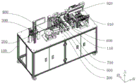
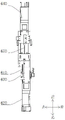
Referring to fig. 1, a terminal and magnetic core assembling machine includes a frame 100, a conveying mechanism 200 is disposed on the frame 100, a first conveying space and a second conveying space are provided in the conveying mechanism 200, the direction of the second conveying space relative to the first conveying space is taken as the relative right direction, the frame 100 is further provided with a gluing mechanism 300, a feeding mechanism 400, a first assembling mechanism 500, a first disassembling mechanism 600, a second assembling mechanism 700, a second disassembling mechanism 800, a blanking mechanism 910 and a transferring mechanism 920, the gluing mechanism 300, the first assembling mechanism 500, the first disassembling mechanism 600, the second assembling mechanism 700, the second disassembling mechanism 800 and the blanking mechanism 910 are arranged in sequence along the direction from the first conveying space to the second conveying space, the feeding mechanism 400 is located beside the first assembling mechanism 500, and the transferring mechanism 920 is located between the first disassembling mechanism 600 and the second assembling mechanism 700.
As can be seen from the above, the rack 100 is provided with the conveying mechanism 200 for conveying an external carrier tape, terminals are uniformly arranged on the carrier tape, the carrier tape is conveyed from the first conveying space to the second conveying space, the terminals on the carrier tape sequentially go through the processes of gluing, first assembling, first disassembling, second assembling, second disassembling and blanking during the conveying process, specifically, the gluing mechanism 300 glues the terminals on the carrier tape, the feeding mechanism 400 feeds the magnetic core, then the first assembling mechanism 500 assembles one side of the magnetic core and the terminals on the carrier tape, the magnetic core and the terminals are positioned on the carrier tape at this time, the magnetic core assembled on the terminals is taken out from the carrier tape by the first disassembling mechanism 600, then the terminals and the magnetic core are transferred to the second assembling mechanism 700 by the transferring mechanism 920, the other side of the magnetic core and the terminals on the carrier tape are assembled by the second assembling mechanism 700, finally, the whole body is detached from the carrier tape by the second detaching mechanism 800 and is discharged and collected by the discharging mechanism 910, so that the whole assembling process is completed, the whole process is automatically completed by machinery, manual operation is reduced, the stability of mechanical operation in each process is higher, the assembling quality is ensured while the assembling efficiency is improved, and the economic benefit is improved.
As shown in fig. 2, the conveying mechanism 200 is used for conveying a carrier tape with terminals, the conveying mechanism 200 includes a reel 210 and a first driving motor 220 rotatably connected to a rack 100, the first driving motor 220 can drive the reel 210 to rotate, a conveying base 230 and a supporting frame 110 are disposed on a top surface of the rack 100, a first conveying wheel 240 and a second conveying wheel 250 are rotatably connected to the conveying base 230, a rotation axis of the reel 210, a rotation axis of the first conveying wheel 240 and a rotation axis of the second conveying wheel 250 all extend in a front-back direction, a first clearance groove is disposed on an outer circumferential wall of the first conveying wheel 240, the first conveying wheel 240 and the second conveying wheel 250 are vertically spaced, a first conveying space is formed between the first conveying wheel 240 and the second conveying wheel 250, a third conveying wheel 260 and a fourth conveying wheel 270 are rotatably connected to the supporting frame 110, be provided with second driving motor 280 on the support frame 110, second driving motor 280 can drive third delivery wheel 260 rotates, the periphery wall of fourth delivery wheel 270 is provided with the fourth dead slot of keeping away, third delivery wheel 260 with fourth delivery wheel 270 sets up along front and back direction interval, the axis of rotation of third delivery wheel 260 with the axis of rotation of fourth delivery wheel 270 all extends along upper and lower direction, third delivery wheel 260 with form between the fourth delivery wheel 270 the second is carried the space. The reel 210 is wound with an external carrier tape to be loaded, the first driving motor 220 drives the reel 210 to rotate, the carrier tape is discharged, one end of the discharged carrier tape is clamped in the first conveying space to be positioned and then clamped in the second conveying space, the second driving motor 280 and the first driving motor 220 synchronously rotate to pull the carrier tape, so that the carrier tape is continuously discharged from the reel 210 and straightened in the first conveying space and the second conveying space, and the terminals are arranged on the carrier tape and can interfere with the conveying wheels when passing through the first conveying space and the second conveying space, so that the first conveying wheel 240 is provided with a first clearance groove, the fourth conveying wheel 270 is provided with a fourth clearance groove for avoiding the terminals, and the carrier tape can be stably conveyed.
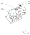
As shown in fig. 3, the gluing mechanism 300 is used for gluing the terminals on the carrier tape, the gluing mechanism 300 includes a gluing base 310, a gluing translation cylinder 320, a gluing translation plate, a gluing lifting cylinder 330, a glue dispensing head 340, a gluing driving motor 350 and a gluing tray 360, the gluing base 310 is fixedly connected to the frame 100, a limiting channel extends along the left and right direction in the gluing base 310, a gluing hole communicated with the limiting channel is formed in the top surface of the gluing base 310, the gluing driving motor 350 is connected to the frame 100, the gluing driving motor 350 can drive the gluing tray 360 to rotate, the gluing tray 360 is located at the rear of the gluing base 310, the rotation axis of the gluing tray 360 extends along the vertical direction, the gluing translation cylinder 320 is connected to the frame 100, the gluing translation cylinder 320 is located in front of the gluing base 310, rubberizing translation board set up in on the rubberizing translation cylinder 320, rubberizing translation cylinder 320 can drive the rubberizing translation board is in go up the adhesive tape 360 with round trip movement between the rubberizing hole, rubberizing lift cylinder 330 connect in on the rubberizing translation board, the head 340 that glues sets up in on the rubberizing lift cylinder 330, rubberizing lift cylinder 330 can drive the head 340 that glues is followed and is close to or keeps away from the directional motion in rubberizing hole. The carrier band passes spacing passageway, and the rubberizing head can make translation, elevating movement respectively under the drive of rubberizing translation cylinder 320, rubberizing lift cylinder 330, and the rubberizing head can be so glue that holds in rubberizing dish 360 glues the carrier band from the rubberizing hole on, and rubberizing driving motor 350 can make rubberizing dish 360 rotate to make the glue in the rubberizing dish 360 flow more evenly.
In practical use, a camera for detecting glue on the terminals of the carrier tape may be further disposed on the frame 100, and whether the glue is applied in place is identified through a captured image.
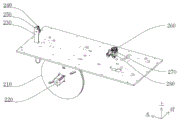
As shown in fig. 4, the feeding mechanism 400 is used for feeding the magnetic core, the feeding mechanism 400 includes a vibrating disk 410 and a straight vibrating guide groove 420, the vibrating disk 410 has a discharge port, one end of the straight vibrating guide groove 420 is connected to the discharge port, the other end of the straight vibrating guide groove 420 is a discharge end, the discharge end is located on the support frame 110, a first guide wheel 430 and a second guide wheel 440 are rotatably connected to the support frame 110, a rotation axis of the first guide wheel 430 and a rotation axis of the second guide wheel 440 extend in a vertical direction, an outer peripheral wall of the second guide wheel 440 is provided with a second clearance groove, the first guide wheel 430 and the second guide wheel 440 are arranged at intervals in a front-back direction, and a guide gap is formed between the first guide wheel 430 and the second guide wheel 440. The vibration disc 410 feeds the magnetic cores from the discharge port to the direct vibration guide groove 420, the magnetic cores are arranged in the direct vibration guide groove 420 along the linear direction and are discharged from the discharge end one by one, the guide gap formed by the first guide wheel 430 and the second guide wheel 440 on the support frame 110 can turn the carrier tape sent out from the first conveying space, so that the carrier tape rotates from the horizontal state to the vertical state, the subsequent process operation is convenient, and similarly, the first empty avoiding groove and the second empty avoiding groove provide an avoiding space for the terminal, so that the carrier tape can stably pass through the guide gap.
As shown in fig. 5, the first assembling mechanism 500 is used for assembling one side of the magnetic core with the terminal on the carrier tape, the first assembling mechanism 500 includes a first assembling table 510, a first assembling electric guide rail 520, a first pushing plate 530, a first assembling translation cylinder 540, a first translation plate, a first positioning pin 551 and a second positioning pin 552, the first assembling electric guide rail 520, the first assembling table 510 and the first assembling translation cylinder 540 are sequentially arranged on the supporting frame 110 along the front-back direction, a first left limiting block and a first right limiting block are arranged on the top surface of the first assembling table 510, the first left limiting block and the first right limiting block are arranged at intervals along the left-right direction, a first limiting space is formed between the first left limiting block and the first right limiting block, the first pushing plate 530 is arranged on the first assembling electric guide rail 520, and the first assembling electric guide rail 520 can drive the first pushing plate 530 to approach to or leave away from the first limiting space The first translational plate is disposed on the first assembling translational cylinder 540, the first assembling translational cylinder 540 can drive the first translational plate to move along the front-back direction, the first positioning pin 551 and the second positioning pin 552 are fixedly connected to the first translational plate, one end of the first positioning pin 551, which is far away from the first translational plate, faces the first left limiting block, and one end of the second positioning pin 552, which is far away from the first translational plate, faces the first right limiting block. Magnetic core material loading is to first assembly table 510, the carrier band that has the terminal passes through between first assembly translation cylinder 540 and the first assembly table 510, during the assembly, utilize first assembly translation cylinder 540 to put and drive the translation board and be close to first assembly table 510 for first locating pin 551 and second locating pin 552 compress tightly the carrier band on first assembly table 510, then utilize first assembly electronic guide rail 520 to drive the push pedal and be close to spacing space, make the push pedal push the magnetic core on first assembly table 510 to spacing space, and press on the terminal, can accomplish the assembly of terminal and magnetic core.
As shown in fig. 6, the first detaching mechanism 600 is used to take out the magnetic cores assembled on the terminals from the carrier tape together, the first detaching mechanism 600 includes a first detaching platform 610, a first detaching electric rail 620, a first pushing rod 630, a second detaching electric rail 640, and a second pushing rod 650, the first detaching electric rail 620, the first detaching platform 610, and the second detaching electric rail 640 are sequentially arranged on the supporting frame 110 along the front-back direction, a first limiting through groove is formed in the top surface of the first detaching platform 610 in an extending manner along the front-back direction, the first pushing rod 630 is disposed on the first detaching electric rail 620, the first detaching electric rail 620 can drive the first pushing rod 630 to move back and forth in the first limiting through groove, the second pushing rod 650 is disposed on the second detaching electric rail 640, one end of the second pushing rod 650 faces the first pushing rod 630, the second detachable electric guide rail 640 can drive the second pushing rod 650 to move along a direction close to or far away from the first limiting through groove. The carrier band passes through between first dismantlement platform 610 and second push rod 650, utilize first dismantlement electronic guide rail 620 to drive first push rod 630 and pass first spacing logical groove, and with first push rod 630 and the terminal and the magnetic core counterbalance of equipment together, utilize second dismantlement electronic guide rail 640 to drive second push rod 650 and be close to first dismantlement platform 610 simultaneously, make second push rod 650 and terminal and the magnetic core equipment combination body together counterbalance, then first push rod 630 and second push rod 650 press from both sides the combination body and transfer to first spacing logical groove department, can tear the terminal out from the carrier band this moment, so can accomplish and dismantle assembled terminal and magnetic core from the carrier band.
As shown in fig. 7, the second assembling mechanism 700 is configured to reassemble the other side of the magnetic core with the terminals on the carrier tape, the second assembling mechanism 700 includes a second assembling platform 710, a second assembling electric guide rail 720, a third pushing rod 730, a second assembling translation cylinder 740, a second translation plate, a third positioning pin 751 and a fourth positioning pin 752, the second assembling electric guide rail 720, the second assembling platform 710 and the second assembling translation cylinder 740 are sequentially arranged on the supporting frame 110 in the front-back direction, a second left limiting block and a second right limiting block are disposed on the top surface of the second assembling platform 710, the second left limiting block and the second right limiting block are disposed at an interval in the left-right direction, a second limiting space is formed between the second left limiting block and the second right limiting block, the third pushing rod 730 is disposed on the second assembling electric guide rail 720, and the second assembling electric guide rail 720 can drive the third pushing rod 730 to approach to or leave away from the second limiting block The second translational plate is disposed on the second assembling translational cylinder 740, the second assembling translational cylinder 740 can drive the second translational plate to move along the front-back direction, the third positioning pin 751 and the fourth positioning pin 752 are fixedly connected to the second translational plate, one end of the third positioning pin 751, which is far away from the second translational plate, faces the second left limiting block, and one end of the fourth positioning pin 752, which is far away from the second translational plate, faces the second right limiting block. The magnetic core with the terminals assembled on one side is transferred to the second assembly table 710, the carrier tape with the terminals passes through the space between the second assembly translation cylinder 740 and the second assembly table 710, during assembly, the second assembly translation cylinder 740 is used for driving the second translation plate to approach the second assembly table 710, so that the third positioning pin 751 and the fourth positioning pin 752 press the carrier tape on the second assembly table 710, then the second assembly electric guide rail 720 is used for driving the third pushing rod 730 to approach the second limit space, so that the third pushing rod 730 pushes the magnetic core on the second assembly table 710 to the second limit space and presses the magnetic core on the terminals, and the terminals can be assembled on the other side wall of the magnetic core.
As shown in fig. 8, the second detaching mechanism 800 is configured to detach the whole from the carrier tape, the second detaching mechanism 800 includes a second detaching table 810, a third detaching electric rail 820, a fourth pushing rod 830, a fifth pushing rod 840, a fourth detaching electric rail 850, a sixth pushing rod 860 and a seventh pushing rod 870, the third detaching electric rail 820, the second detaching table 810 and the fourth detaching electric rail 850 are sequentially arranged on the supporting frame 110 in the front-back direction, a second limiting through groove and a third limiting through groove are arranged on the top surface of the second detaching table 810 at intervals in the left-right direction, the second limiting through groove and the third limiting through groove both extend in the front-back direction, the fourth pushing rod 830 and the fifth pushing rod 840 are arranged on the third detaching electric rail 820, and the third detaching electric rail 820 can drive the fourth pushing rod 830, the fifth pushing rod 840, the second limiting through groove, the fifth pushing rod 840, the third detaching electric rail 820, and the third detaching electric rail, The third limiting through groove moves back and forth, the sixth push rod 860 and the seventh push rod 870 are disposed on the fourth detachable electric guide rail 850, one end of the sixth push rod 860 faces the fourth push rod 830, one end of the seventh push rod 870 faces the fifth push rod 840, and the fourth detachable electric guide rail 850 can drive the fifth push rod 840 and the seventh push rod 870 to move along the direction close to or away from the second limiting through groove and the third limiting through groove, respectively. In order to improve the production rhythm, two groups of pushing rods are used for disassembling two assembled products at a time, that is, the fourth pushing rod 830 and the sixth pushing rod 860 form a group together, the fifth pushing rod 840 and the seventh pushing rod 870 form a group together, and the two groups of pushing rods can pull out the assembled products on the carrier tape to the second limiting through groove and the third limiting through groove to complete the disassembly of the products from the carrier tape.
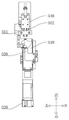
As shown in fig. 9, the blanking mechanism 910 is used for blanking and collecting products, the blanking mechanism 910 includes a blanking frame 911, a portal frame 912, a blanking electric guide rail 913, a blanking translational plate, a blanking lifting cylinder 914 and a blanking pneumatic finger 915, the blanking frame 911 and the portal frame 912 are connected to the rack 100, the blanking electric guide rail 913 is connected to the portal frame 912, the blanking translational plate is arranged on the blanking electric guide rail 913, the blanking electric guide rail 913 can drive the blanking translational plate to move back and forth between the second dismounting mechanism 800 and the blanking frame 911, the blanking lifting cylinder 914 is connected to the blanking translational plate, the blanking pneumatic finger 915 is arranged on the blanking lifting cylinder 914, and the blanking lifting cylinder 914 can drive the blanking pneumatic finger 915 to move along the vertical direction. The pneumatic fingers 915 for blanking can respectively perform translation and lifting motions under the driving of the electric guide rails 913 for blanking and the lifting cylinder 914 for blanking, and the pneumatic fingers 915 for blanking can clamp the products in the second limiting through groove and the third limiting through groove into the blanking frame 911 to complete the collection and blanking of the products.
While the preferred embodiments of the present invention have been illustrated and described, it will be understood by those skilled in the art that the present invention is not limited to the details of the embodiments shown and described, but is capable of numerous equivalents and substitutions without departing from the spirit of the invention as set forth in the claims appended hereto.
Claims (9)
1. The utility model provides a terminal and magnetic core kludge which characterized in that: the automatic feeding device comprises a rack (100), wherein a conveying mechanism (200) is arranged on the rack (100), a first conveying space and a second conveying space are arranged in the conveying mechanism (200), the position of the second conveying space relative to the first conveying space is the opposite right direction, a gluing mechanism (300), a feeding mechanism (400), a first assembling mechanism (500), a first disassembling mechanism (600), a second assembling mechanism (700), a second disassembling mechanism (800), a discharging mechanism (910) and a transferring mechanism (920) are further arranged on the rack (100), the gluing mechanism (300), the first assembling mechanism (500), the first disassembling mechanism (600), the second assembling mechanism (700), the second disassembling mechanism (800) and the discharging mechanism (910) are sequentially arranged along the direction from the first conveying space to the second conveying space, and the feeding mechanism (400) is positioned beside the first assembling mechanism (500), the transfer mechanism (920) is located between the first disassembly mechanism (600) and the second assembly mechanism (700), the conveying mechanism (200) comprises a reel (210) and a first driving motor (220) which are rotatably connected to the rack (100), the first driving motor (220) can drive the reel (210) to rotate, a conveying seat (230) and a supporting frame (110) are arranged on the top surface of the rack (100), a first conveying wheel (240) and a second conveying wheel (250) are rotatably connected to the conveying seat (230), the rotation axis of the reel (210), the rotation axis of the first conveying wheel (240) and the rotation axis of the second conveying wheel (250) all extend in the front-back direction, a first clearance groove is formed in the peripheral wall of the first conveying wheel (240), and the first conveying wheel (240) and the second conveying wheel (250) are arranged at intervals in the up-down direction, first delivery wheel (240) with form between second delivery wheel (250) first transport space, it is connected with third delivery wheel (260) and fourth delivery wheel (270) to rotate on support frame (110), be provided with second driving motor (280) on support frame (110), second driving motor (280) can drive third delivery wheel (260) rotate, the periphery wall of fourth delivery wheel (270) is provided with the fourth and keeps away the dead slot, third delivery wheel (260) with fourth delivery wheel (270) set up along the preceding rear direction interval, the axis of rotation of third delivery wheel (260) with the axis of rotation of fourth delivery wheel (270) all extends along the upper and lower direction, third delivery wheel (260) with form between the fourth delivery wheel (270) second transport space.
2. The terminal and magnetic core assembling machine according to claim 1, wherein: gluing mechanism (300) including rubberizing seat (310), rubberizing translation cylinder (320), rubberizing translation board, rubberizing lift cylinder (330), dispensing head (340), rubberizing driving motor (350), rubberizing dish (360), rubberizing seat (310) fixed connection in on frame (100), extend along left right direction in rubberizing seat (310) and have spacing passageway, the top surface of rubberizing seat (310) be provided with the rubberizing hole that spacing passageway communicates each other, rubberizing driving motor (350) connect in on frame (100), rubberizing driving motor (350) can drive rubberizing dish (360) rotate, rubberizing dish (360) are located the rear of rubberizing seat (310), the axis of rotation of rubberizing dish (360) extends along vertical direction, rubberizing translation cylinder (320) connect in on frame (100), rubberizing translation cylinder (320) are located the place ahead of rubberizing seat (310), rubberizing translation board set up in on rubberizing translation cylinder (320), rubberizing translation cylinder (320) can drive rubberizing translation board is in rubberizing dish (360) with round trip movement between the rubberizing hole, rubberizing lift cylinder (330) connect in on the rubberizing translation board, the head of dispensing (340) set up in on rubberizing lift cylinder (330), rubberizing lift cylinder (330) can drive the head of dispensing (340) is along being close to or keeping away from the direction motion in rubberizing hole.
3. The terminal and magnetic core assembling machine according to claim 1, wherein: feed mechanism (400) including vibration dish (410) with directly vibrate guide slot (420), vibration dish (410) have the discharge gate, the one end of directly vibrating guide slot (420) connect in the discharge gate, the other end of directly vibrating guide slot (420) is the discharge end, the discharge end is located on support frame (110), it is connected with first leading wheel (430) and second leading wheel (440) to rotate on support frame (110), the axis of rotation of first leading wheel (430) with the axis of rotation of second leading wheel (440) extends along vertical direction, the periphery wall of second leading wheel (440) is provided with the second and keeps away the dead slot, first leading wheel (430) with second leading wheel (440) set up along the fore-and-aft direction interval, first leading wheel (430) with form the guiding clearance between second leading wheel (440).
4. The terminal and magnetic core assembling machine according to claim 1, wherein: the first assembling mechanism (500) comprises a first assembling table (510), a first assembling electric guide rail (520), a first pushing plate (530), a first assembling translation cylinder (540), a first translation plate, a first positioning pin (551) and a second positioning pin (552), the first assembling electric guide rail (520), the first assembling table (510) and the first assembling translation cylinder (540) are sequentially arranged on the supporting frame (110) along the front-back direction, a first left limiting block and a first right limiting block are arranged on the top surface of the first assembling table (510) at intervals along the left-right direction, a first limiting space is formed between the first left limiting block and the first right limiting block, the first pushing plate (530) is arranged on the first assembling electric guide rail (520), and the first assembling electric guide rail (520) can drive the first pushing plate (530) to be close to or far away from the first limiting space, the first translation plate is arranged on the first assembling translation cylinder (540), the first assembling translation cylinder (540) can drive the first translation plate to move along the front-back direction, the first positioning pin (551) and the second positioning pin (552) are fixedly connected to the first translation plate, one end, far away from the first translation plate, of the first positioning pin (551) is right opposite to the first left limiting block, and one end, far away from the first translation plate, of the second positioning pin (552) is right opposite to the first right limiting block.
5. The terminal and magnetic core assembling machine according to claim 1, wherein: the first dismounting mechanism (600) comprises a first dismounting table (610), a first dismounting electric guide rail (620), a first pushing rod (630), a second dismounting electric guide rail (640) and a second pushing rod (650), wherein the first dismounting electric guide rail (620), the first dismounting table (610) and the second dismounting electric guide rail (640) are sequentially arranged on the support frame (110) along the front-back direction, a first limiting through groove is formed in the top surface of the first dismounting table (610) in an extending manner along the front-back direction, the first pushing rod (630) is arranged on the first dismounting electric guide rail (620), the first dismounting electric guide rail (620) can drive the first pushing rod (630) to move back and forth in the first limiting through groove, the second pushing rod (650) is arranged on the second dismounting electric guide rail (640), one end of the second pushing rod (650) is opposite to the first pushing rod (630), the second detachable electric guide rail (640) can drive the second pushing rod (650) to move along the direction close to or far away from the first limiting through groove.
6. The terminal and magnetic core assembling machine according to claim 1, wherein: the second assembling mechanism (700) comprises a second assembling table (710), a second assembling electric guide rail (720), a third pushing rod (730), a second assembling translation cylinder (740), a second translation plate, a third positioning pin (751) and a fourth positioning pin (752), the second assembling electric guide rail (720), the second assembling table (710) and the second assembling translation cylinder (740) are sequentially arranged on the supporting frame (110) along the front-back direction, a second left limiting block and a second right limiting block are arranged on the top surface of the second assembling table (710) at intervals along the left-right direction, a second limiting space is formed between the second left limiting block and the second right limiting block, the third pushing rod (730) is arranged on the second assembling electric guide rail (720), and the second assembling electric guide rail (720) can drive the third pushing rod (730) to be close to or far away from the second limiting space, the second translation plate is arranged on the second assembling translation cylinder (740), the second assembling translation cylinder (740) can drive the second translation plate to move along the front-back direction, the third positioning pin (751) and the fourth positioning pin (752) are fixedly connected to the second translation plate, one end, far away from the second translation plate, of the third positioning pin (751) is right opposite to the second left limiting block, and one end, far away from the second translation plate, of the fourth positioning pin (752) is right opposite to the second right limiting block.
7. The terminal and magnetic core assembling machine according to claim 1, wherein: the second dismounting mechanism (800) comprises a second dismounting table (810), a third dismounting electric guide rail (820), a fourth pushing rod (830), a fifth pushing rod (840), a fourth dismounting electric guide rail (850), a sixth pushing rod (860) and a seventh pushing rod (870), the third dismounting electric guide rail (820), the second dismounting table (810) and the fourth dismounting electric guide rail (850) are sequentially arranged on the support frame (110) along the front-back direction, a second limiting through groove and a third limiting through groove are arranged on the top surface of the second dismounting table (810) along the left-right direction at intervals, the second limiting through groove and the third limiting through groove extend along the front-back direction, the fourth pushing rod (830) and the fifth pushing rod (840) are arranged on the third dismounting electric guide rail (820), and the third dismounting electric guide rail (820) can drive the fourth pushing rod (830), Fifth push rod (840) is respectively in the spacing logical groove of second, the spacing logical inslot round trip movement of third, sixth push rod (860) with seventh push rod (870) set up in fourth dismantlement electric rail (850), the one end of sixth push rod (860) is just right to fourth push rod (830), the one end of seventh push rod (870) is just right to fifth push rod (840), fourth dismantlement electric rail (850) can drive fifth push rod (840), seventh push rod (870) are respectively along being close to or keeping away from the direction motion of the spacing logical groove of second, the spacing logical groove of third.
8. The terminal and magnetic core assembling machine according to claim 1, wherein: the blanking mechanism (910) comprises a blanking frame (911), a portal frame (912), a blanking electric guide rail (913), a blanking translation plate, a blanking lifting cylinder (914) and a blanking pneumatic finger (915), the blanking rack (911) and the portal frame (912) are connected to the frame (100), the blanking electric guide rail (913) is connected to the portal frame (912), the blanking translation plate is arranged on the blanking electric guide rail (913), the blanking electric guide rail (913) can drive the blanking translation plate to move back and forth between the second dismounting mechanism (800) and the blanking frame (911), the blanking lifting cylinder (914) is connected to the blanking translation plate, the blanking pneumatic finger (915) is arranged on the blanking lifting cylinder (914), the blanking lifting cylinder (914) can drive the blanking pneumatic finger (915) to move along the vertical direction.
9. A terminal and magnetic core assembling machine according to claim 8, characterized in that: transfer mechanism (920) including transfer electric guide rail (921), transfer board, transfer lift cylinder (922), transfer driving motor (923), transfer pneumatic finger (924), transfer electric guide rail (921) connect in on portal frame (912), transfer board connect in transfer electric guide rail (921), it can drive to transfer electric guide rail (921) the board is in between first disassembly body (600) and second assembly body (700) round trip movement, transfer lift cylinder (922) connect in on the transfer board, transfer driving motor (923) set up in transfer lift cylinder (922), transfer lift cylinder (922) can drive transfer driving motor (923) along vertical direction motion, transfer pneumatic finger (924) set up in transfer driving motor (923), transfer driving motor (923) can drive transfer pneumatic finger (924) to rotate, the axis of rotation of the mobile pneumatic finger (924) extends in a vertical direction.
Priority Applications (1)
| Application Number | Priority Date | Filing Date | Title |
|---|---|---|---|
| CN202010604134.XA CN111508697B (en) | 2020-06-29 | 2020-06-29 | Terminal and magnetic core kludge |
Applications Claiming Priority (1)
| Application Number | Priority Date | Filing Date | Title |
|---|---|---|---|
| CN202010604134.XA CN111508697B (en) | 2020-06-29 | 2020-06-29 | Terminal and magnetic core kludge |
Publications (2)
| Publication Number | Publication Date |
|---|---|
| CN111508697A CN111508697A (en) | 2020-08-07 |
| CN111508697B true CN111508697B (en) | 2020-10-23 |
Family
ID=71877257
Family Applications (1)
| Application Number | Title | Priority Date | Filing Date |
|---|---|---|---|
| CN202010604134.XA Active CN111508697B (en) | 2020-06-29 | 2020-06-29 | Terminal and magnetic core kludge |
Country Status (1)
| Country | Link |
|---|---|
| CN (1) | CN111508697B (en) |
Families Citing this family (3)
| Publication number | Priority date | Publication date | Assignee | Title |
|---|---|---|---|---|
| CN113035542B (en) * | 2021-02-24 | 2022-07-26 | 广东昭信智能装备有限公司 | Chip inductor production line |
| CN113579679B (en) * | 2021-08-10 | 2024-06-07 | 全南群英达电子有限公司 | Automatic magnetic head forming device |
| CN118197780B (en) * | 2024-05-16 | 2024-08-23 | 广东昭信智能装备有限公司 | Dispensing terminal machine and system |
Citations (11)
| Publication number | Priority date | Publication date | Assignee | Title |
|---|---|---|---|---|
| JPH03120177A (en) * | 1989-09-29 | 1991-05-22 | Toshiba Corp | Tape winding device |
| TW508598B (en) * | 2001-06-07 | 2002-11-01 | De-Lu Tzeng | Manufacturing method for thin inductor |
| JP2007266271A (en) * | 2006-03-28 | 2007-10-11 | Tdk Corp | Core mounting method and device |
| CN106571218A (en) * | 2016-11-03 | 2017-04-19 | 深圳市京泉华科技股份有限公司 | Automatic processing equipment and method of electronic transformer lead |
| CN206490283U (en) * | 2017-02-17 | 2017-09-12 | 广东昭信智能装备有限公司 | It is a kind of to be used for inductance wire rod and the laser welding apparatus of terminal melting welding |
| CN206619495U (en) * | 2017-02-24 | 2017-11-07 | 珠海航宇自动化设备有限公司 | A kind of inductance terminal and magnetic core bonding mechanism |
| CN107393712A (en) * | 2017-07-26 | 2017-11-24 | 东莞市嘉龙海杰电子科技有限公司 | Magnetic core copper-surfaced paper tinsel and spot gluing equipment |
| CN207663926U (en) * | 2017-08-01 | 2018-07-27 | 东莞市大研自动化设备有限公司 | A kind of assembly of magnetic core automatically dropping glue cuts baking machine |
| CN208299187U (en) * | 2018-06-06 | 2018-12-28 | 广东昭信智能装备有限公司 | A kind of terminal assembling machine |
| CN209418308U (en) * | 2019-01-02 | 2019-09-20 | 珠海航宇自动化设备有限公司 | A kind of transformer coiling mechanism |
| CN110473700A (en) * | 2019-08-24 | 2019-11-19 | 南京金惠凯电子科技有限公司 | The production equipment of bar magnet coil |
Family Cites Families (4)
| Publication number | Priority date | Publication date | Assignee | Title |
|---|---|---|---|---|
| JPS57128016A (en) * | 1981-01-31 | 1982-08-09 | Sumida Denki Kk | Automatic manufacturing machine for inductor |
| CN203205237U (en) * | 2013-03-04 | 2013-09-18 | 浙江田中精机股份有限公司 | Magnetic core assembling machine |
| NL2011753C2 (en) * | 2013-11-07 | 2015-05-11 | Tecnotion B V | Multi-layer flat wire coil. |
| US9881725B2 (en) * | 2014-11-21 | 2018-01-30 | Cisco Technology, Inc. | Ethernet magnetics package wire terminations |
-
2020
- 2020-06-29 CN CN202010604134.XA patent/CN111508697B/en active Active
Patent Citations (11)
| Publication number | Priority date | Publication date | Assignee | Title |
|---|---|---|---|---|
| JPH03120177A (en) * | 1989-09-29 | 1991-05-22 | Toshiba Corp | Tape winding device |
| TW508598B (en) * | 2001-06-07 | 2002-11-01 | De-Lu Tzeng | Manufacturing method for thin inductor |
| JP2007266271A (en) * | 2006-03-28 | 2007-10-11 | Tdk Corp | Core mounting method and device |
| CN106571218A (en) * | 2016-11-03 | 2017-04-19 | 深圳市京泉华科技股份有限公司 | Automatic processing equipment and method of electronic transformer lead |
| CN206490283U (en) * | 2017-02-17 | 2017-09-12 | 广东昭信智能装备有限公司 | It is a kind of to be used for inductance wire rod and the laser welding apparatus of terminal melting welding |
| CN206619495U (en) * | 2017-02-24 | 2017-11-07 | 珠海航宇自动化设备有限公司 | A kind of inductance terminal and magnetic core bonding mechanism |
| CN107393712A (en) * | 2017-07-26 | 2017-11-24 | 东莞市嘉龙海杰电子科技有限公司 | Magnetic core copper-surfaced paper tinsel and spot gluing equipment |
| CN207663926U (en) * | 2017-08-01 | 2018-07-27 | 东莞市大研自动化设备有限公司 | A kind of assembly of magnetic core automatically dropping glue cuts baking machine |
| CN208299187U (en) * | 2018-06-06 | 2018-12-28 | 广东昭信智能装备有限公司 | A kind of terminal assembling machine |
| CN209418308U (en) * | 2019-01-02 | 2019-09-20 | 珠海航宇自动化设备有限公司 | A kind of transformer coiling mechanism |
| CN110473700A (en) * | 2019-08-24 | 2019-11-19 | 南京金惠凯电子科技有限公司 | The production equipment of bar magnet coil |
Also Published As
| Publication number | Publication date |
|---|---|
| CN111508697A (en) | 2020-08-07 |
Similar Documents
| Publication | Publication Date | Title |
|---|---|---|
| CN111508697B (en) | Terminal and magnetic core kludge | |
| CN107046145B (en) | Automatic core-closing rubberizing machine for power battery | |
| CN105836199B (en) | full-automatic film sticking machine | |
| CN110125643B (en) | Full-automatic ribbon assembling machine | |
| CN109823833A (en) | Automatic scoreboard equipment and its operating method | |
| CN109128739A (en) | A kind of product automation assembling equipment | |
| CN109986324A (en) | A kind of dress net equipment with image recognition precise locating function | |
| CN115172040A (en) | Inductance single line cross coiling machine | |
| CN208290580U (en) | A kind of book flask kludge | |
| CN113458762A (en) | Assembly equipment with automatic pressure maintaining function | |
| CN111392411B (en) | Full-automatic assembling equipment for connector | |
| CN205868697U (en) | Point glue of DIP component is inlayed lid and is assembled all -in -one | |
| CN210172965U (en) | Second-generation pump core detection assembling machine | |
| CN210504582U (en) | Cotton automatic feeding of bubble of cotton kludge of ribbon bubble | |
| CN109801768B (en) | Motor and method for magnetizing magnetic frame and magnetic strip of motor | |
| CN114130609B (en) | Data line dispensing and assembling machine | |
| CN211238789U (en) | Power connection terminal kludge | |
| CN216290588U (en) | Motor assembling machine | |
| CN110980285B (en) | Automatic feeding and coding device for battery module shell | |
| CN211238381U (en) | Automatic compound make-up machine of pole piece | |
| CN210501119U (en) | Rope clamping and transferring device applied to rope handle cutting and swinging machine | |
| CN109687654B (en) | Full-automatic assembling system and assembling method for motor casing | |
| CN219403175U (en) | Automatic shaping assembly machine | |
| CN219582732U (en) | Magnetic force piece-sucking assembly equipment | |
| CN221290166U (en) | Ship-shaped overload protection full-automatic assembly machine |
Legal Events
| Date | Code | Title | Description |
|---|---|---|---|
| PB01 | Publication | ||
| PB01 | Publication | ||
| SE01 | Entry into force of request for substantive examination | ||
| SE01 | Entry into force of request for substantive examination | ||
| GR01 | Patent grant | ||
| GR01 | Patent grant |