CN111495498A - Flour production and processing method - Google Patents
Flour production and processing method Download PDFInfo
- Publication number
- CN111495498A CN111495498A CN202010389405.4A CN202010389405A CN111495498A CN 111495498 A CN111495498 A CN 111495498A CN 202010389405 A CN202010389405 A CN 202010389405A CN 111495498 A CN111495498 A CN 111495498A
- Authority
- CN
- China
- Prior art keywords
- grinding
- flour
- plate
- rod
- crops
- Prior art date
- Legal status (The legal status is an assumption and is not a legal conclusion. Google has not performed a legal analysis and makes no representation as to the accuracy of the status listed.)
- Granted
Links
Images


Classifications
-
- B—PERFORMING OPERATIONS; TRANSPORTING
- B02—CRUSHING, PULVERISING, OR DISINTEGRATING; PREPARATORY TREATMENT OF GRAIN FOR MILLING
- B02C—CRUSHING, PULVERISING, OR DISINTEGRATING IN GENERAL; MILLING GRAIN
- B02C9/00—Other milling methods or mills specially adapted for grain
- B02C9/04—Systems or sequences of operations; Plant
-
- B—PERFORMING OPERATIONS; TRANSPORTING
- B02—CRUSHING, PULVERISING, OR DISINTEGRATING; PREPARATORY TREATMENT OF GRAIN FOR MILLING
- B02C—CRUSHING, PULVERISING, OR DISINTEGRATING IN GENERAL; MILLING GRAIN
- B02C23/00—Auxiliary methods or auxiliary devices or accessories specially adapted for crushing or disintegrating not provided for in preceding groups or not specially adapted to apparatus covered by a single preceding group
- B02C23/08—Separating or sorting of material, associated with crushing or disintegrating
- B02C23/14—Separating or sorting of material, associated with crushing or disintegrating with more than one separator
-
- B—PERFORMING OPERATIONS; TRANSPORTING
- B02—CRUSHING, PULVERISING, OR DISINTEGRATING; PREPARATORY TREATMENT OF GRAIN FOR MILLING
- B02C—CRUSHING, PULVERISING, OR DISINTEGRATING IN GENERAL; MILLING GRAIN
- B02C4/00—Crushing or disintegrating by roller mills
- B02C4/02—Crushing or disintegrating by roller mills with two or more rollers
- B02C4/06—Crushing or disintegrating by roller mills with two or more rollers specially adapted for milling grain
-
- B—PERFORMING OPERATIONS; TRANSPORTING
- B02—CRUSHING, PULVERISING, OR DISINTEGRATING; PREPARATORY TREATMENT OF GRAIN FOR MILLING
- B02C—CRUSHING, PULVERISING, OR DISINTEGRATING IN GENERAL; MILLING GRAIN
- B02C4/00—Crushing or disintegrating by roller mills
- B02C4/10—Crushing or disintegrating by roller mills with a roller co-operating with a stationary member
-
- B—PERFORMING OPERATIONS; TRANSPORTING
- B02—CRUSHING, PULVERISING, OR DISINTEGRATING; PREPARATORY TREATMENT OF GRAIN FOR MILLING
- B02C—CRUSHING, PULVERISING, OR DISINTEGRATING IN GENERAL; MILLING GRAIN
- B02C4/00—Crushing or disintegrating by roller mills
- B02C4/28—Details
- B02C4/42—Driving mechanisms; Roller speed control
-
- B—PERFORMING OPERATIONS; TRANSPORTING
- B07—SEPARATING SOLIDS FROM SOLIDS; SORTING
- B07B—SEPARATING SOLIDS FROM SOLIDS BY SIEVING, SCREENING, SIFTING OR BY USING GAS CURRENTS; SEPARATING BY OTHER DRY METHODS APPLICABLE TO BULK MATERIAL, e.g. LOOSE ARTICLES FIT TO BE HANDLED LIKE BULK MATERIAL
- B07B1/00—Sieving, screening, sifting, or sorting solid materials using networks, gratings, grids, or the like
- B07B1/46—Constructional details of screens in general; Cleaning or heating of screens
- B07B1/50—Cleaning
- B07B1/52—Cleaning with brushes or scrapers
- B07B1/522—Cleaning with brushes or scrapers with brushes
Abstract
The invention relates to a flour production and processing method, mainly include the following steps, screening operation, washing operation, milling operation, screening treatment and packing operation, the crops grinding apparatus used includes the bottom plate, grinder, reducing mechanism and cleaning device, the invention can solve the following difficult problem existing in the existing flour production and grinding, a, while grinding traditional flour, often need to use the stone mill to grind the operation to the crops manually, and need to promote the stone mill manually, it is time-consuming and laborious to promote the stone mill manually, the crops grind the inefficiency, and the crops grind insufficiently, influence the quality of the flour; b traditional crops grinding machine is when grinding crops, and is inhomogeneous to the smashing of crops to the condition that the filtration pore was plugged up to the great crop granule of flour easy emergence in the screening process, and manual handling is comparatively troublesome, influences the grinding efficiency of flour, and the remaining flour on the screening net is more, extravagant raw and other materials improve the efficiency that the flour ground.
Description
Technical Field
The invention relates to the technical field of flour production and processing, in particular to a flour production and processing method.
Background
The flour is a powder ground by crops, and can be divided into high gluten flour, medium gluten flour, low gluten flour and non-gluten flour according to the content of protein in the flour, the grade of the flour is directly related to the content of mineral substances (ash) in the husk and germ of the wheat grain, the higher the content of the mineral substances is, the lower the grade of the flour is, and on the contrary, the lower the content of the mineral substances is, the higher the grade of the flour is, and the crops need to be ground when the flour is produced.
However, the following problems in the existing flour production grinding are that a, in the traditional flour grinding, a stone mill is often needed to be manually used for grinding crops, the stone mill needs to be manually pushed, the manual pushing of the stone mill wastes time and labor, the grinding efficiency is low, the grinding of crop particles is insufficient, and the quality of the flour is affected; b traditional flour grinding machine smashes inhomogeneous when grinding the crops granule to the condition that the filtration pore was plugged up to the great crops granule takes place easily to flour in the screening process, and manual handling is comparatively troublesome, influences the grinding efficiency of flour, and the remaining flour on the screening net is more, extravagant raw and other materials, artificial intensity of labour when can reducing the flour and grind improves the efficiency that the flour ground.
Disclosure of Invention
In order to solve the problems, the invention provides a flour production and processing method which can solve the problems in the flour production and grinding process.
In order to achieve the purpose, the invention adopts the following technical scheme to realize the purpose: a flour production and processing method mainly comprises the following steps:
screening, namely screening crops to screen out impurities in the crops, so that the crops are clean and free of impurities to obtain clean crops;
step two, cleaning operation is carried out, wherein the clean crops obtained in the step one are cleaned to obtain cleaned crops;
step three, performing flour grinding operation, namely putting the cleaned crops obtained in the step two into crop grinding equipment for flour grinding operation to obtain flour with flour being ground;
screening, namely screening the flour which is milled in the step three, and separating the flour and the wheat bran to obtain finished flour;
and step five, packaging operation, namely packaging the finished flour obtained in the step four to obtain the packaged flour.
The crop grinding equipment used in the steps comprises a base plate, a grinding device, a smashing device and a sweeping device, wherein the grinding device is installed on the base plate, the smashing device is installed on the grinding device, and the sweeping device is installed on the smashing device.
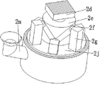
Grinder including grinding ring, apron, L template, a motor, power round bar, slip round bar, square bar, stripper plate, connection round bar, location plectane, grinding roller, grinding net and feed inlet, the bottom plate around the symmetry install the L template, install the grinding ring between the L template, grinding ring installs the apron in the upper end, install the location plectane between the inner wall of grinding ring middle-end, location round bar centre of a circle department has seted up the circular slot, install the connection round bar through the bearing in the circular slot, it is connected with grinding roller to connect the round bar lower extreme, connect the round bar upper end and install power round bar, No. one motor is installed to the apron lower extreme, a motor output is connected at power round bar, has seted up the power groove along its circumference direction on the power round bar outer wall, evenly seted up the straight flute along its circumference direction on the location plectane, install the square bar through sliding fit's mode in the straight flute, the slip round bar is installed to the square bar upper end, and the slip round bar passes through sliding fit's mode and installs in the power groove on the square bar lower extreme, the inner wall of square bar lower extreme installs the power net on the circular slot, grinding roller, grinding operation improves the grinding quality of crops.
The crushing device comprises a crushing box, a connecting plate, a second motor, a crushing roller, a crushing box, a power box, a third motor, a rotary round rod, a feeding plate, a first bevel gear, a first gear, a crushing roller, a rotary round rod and a second gear, wherein the lower end of the grinding ring is provided with the crushing box, the connecting plate is arranged between the inner walls of the left end and the right end of the crushing box, the middle end of the lower side of the connecting plate is provided with a groove, the inner wall of the groove is provided with the second motor, the output end of the second motor is provided with the crushing roller, the crushing roller and the crushing box are mutually matched for use, the lower end of the crushing box is provided with the crushing box, the feeding plate is symmetrically arranged between the inner walls of the left end and the right end of the upper side of the crushing box in the front-back direction, the outer wall of the right end of the crushing, and the rotary round bar left end passes broken case right-hand member and passes through the bearing and install on broken case left end inner wall, lie in on the rotary round bar and install the gear No. one between broken case right-hand member outer wall and the bevel gear No. one, headstock right-hand member inner wall rear side is installed the rotary round bar through the bearing, and the rotary round bar left end passes broken case right-hand member and passes through the bearing and install on broken case left end inner wall, lie in on the rotary round bar and install No. two gears with gear intermeshing in the headstock, lie in on rotary round bar and the rotary round bar and install crushing roller in the broken case, drive crushing roller through No. two motors and rotate, crushing roller can smash the operation to crops.
The sweeping device comprises a supporting plate, a sweeping round rod, a second bevel gear, a power round plate, a straight plate, a return spring rod, a brush, a screening net, a square plate, a first collecting box, a first discharging port and a second discharging port, wherein the supporting plate is symmetrically arranged at the lower side of the outer wall of the right end of the crushing box from top to bottom, the sweeping round rod is arranged on the supporting plates at the upper end and the lower end through a bearing, the second bevel gear meshed with the first bevel gear is arranged at the upper end of the sweeping round rod, the power round plate is eccentrically arranged between the supporting plates at the upper end and the lower end of the sweeping round rod, the square groove is arranged at the right end of the crushing box, the long strip groove is arranged at the left end of the crushing box, the straight plate is arranged in the square groove in a sliding fit manner, the return plate is arranged at the upper end of the straight plate, the return spring rod is symmetrically arranged on, the brush is installed to the straight board left end position in broken incasement, install the screening net between the broken incasement lower extreme inner wall, install on the broken case left end outer wall with the discharge gate of rectangular groove mutually supporting use, it installs the square plate to lie in rectangular groove lower extreme on the broken case left end outer wall, install a collecting box on the square plate, No. two discharge gates are installed to broken case lower extreme, the brush on can driving the straight board through the resilience of power plectane rotation and return spring pole is controlled straight reciprocating motion, make the brush can collect the operation to the flour on the screening net.
As a preferred technical scheme of the invention, the power groove is an annular groove which is connected with each other along the circumferential direction of the outer wall of the power round rod in a V shape, so that the power groove can drive the extrusion plate to do vertical linear reciprocating motion by sliding the round rod and the square rod, and the extrusion plate can perform extrusion flapping operation on crops.
As a preferable technical scheme of the invention, the upper end of the grinding round roller is an arc surface, and the grinding net and the extrusion plate are matched with the arc surface at the upper end of the grinding round roller for use, so that the crop can be ground.
As a preferred technical scheme of the invention, the lower end of the bottom plate is uniformly provided with the supporting rods, so that the grinding stability of crops is improved.
As a preferred technical scheme of the invention, the middle part of the upper end of the bottom plate is provided with a second collecting box which can collect flour.
The invention has the beneficial effects that:
1. the invention can solve the following problems existing in the prior flour production grinding, a, in the traditional flour grinding, the stone mill is often needed to be manually used for grinding crops, the stone mill needs to be manually pushed, the manual pushing of the stone mill wastes time and labor, the grinding efficiency is low, the grinding of crop particles is insufficient, and the quality of the flour is influenced; b traditional flour grinding machine smashes inhomogeneous when grinding the crops granule to the condition that the filtration pore was plugged up to the great crops granule takes place easily to flour in the screening process, and manual handling is comparatively troublesome, influences the grinding efficiency of flour, and the remaining flour on the screening net is more, extravagant raw and other materials, artificial intensity of labour when can reducing the flour and grind improves the efficiency that the flour ground.
2. According to the grinding device, the grinding ring, the cover plate, the L template, the first motor, the power round rod, the sliding round rod, the square rod, the extrusion plate, the connecting round rod, the positioning round plate, the grinding round roller and the grinding net are matched with one another to work, so that the power round rod can drive the grinding round roller to grind crops, the power groove formed in the power round rod drives the sliding round rod and the square rod to drive the extrusion plate to do vertical linear reciprocating motion, the extrusion plate can extrude and flap the crops, the grinding operation is performed on the crops, and the grinding quality of the crops can be improved.
3. The crushing device and the sweeping device designed in the invention can crush crops by the crushing roller through the mutual matching operation among the crushing box, the connecting plate, the second motor, the crushing roller, the crushing box, the power box, the third motor, the rotary round rod, the feeding plate, the first bevel gear, the first gear, the crushing roller, the rotary round rod and the second gear, can grind the crops again, can drive the hairbrush on the straight plate to do left-right linear reciprocating motion through the mutual matching operation among the supporting plate, the sweeping round rod, the second bevel gear, the power round plate, the straight plate, the return spring rod, the hairbrush, the screening net, the square plate, the first collecting box, the first discharge port and the second discharge port, can drive the hairbrush on the straight plate to do left-right linear reciprocating motion through the rotation of the power round plate and the return spring rod, can collect flour on the screening net by the hairbrush, and ensure the smoothness of the screening net, the mesh blockage can not occur, and the grinding efficiency of the crops is improved.
Drawings
The invention is further illustrated with reference to the following figures and examples.
FIG. 1 is a flow chart of the operation of the present invention;
FIG. 2 is a schematic view of the construction of the crop grinding apparatus of the present invention;
FIG. 3 is a cross-sectional view of FIG. 2 of the present invention;
FIG. 4 is a cross-sectional view taken along line A-A of FIG. 3 in accordance with the present invention;
FIG. 5 is a schematic view of a partial structure of the crushing apparatus according to the present invention;
FIG. 6 is a schematic view of a partial structure of the polishing apparatus of the present invention.
Detailed Description
The embodiments of the invention will be described in detail below with reference to the drawings, but the invention can be implemented in many different ways as defined and covered by the claims.
As shown in fig. 1 to 6, a flour production and processing method mainly comprises the following steps:
screening, namely screening crops to screen out impurities in the crops, so that the crops are clean and free of impurities to obtain clean crops;
step two, cleaning operation is carried out, wherein the clean crops obtained in the step one are cleaned to obtain cleaned crops;
step three, performing flour grinding operation, namely putting the cleaned crops obtained in the step two into crop grinding equipment for flour grinding operation to obtain flour with flour being ground;
screening, namely screening the flour which is milled in the step three, and separating the flour and the wheat bran to obtain finished flour;
and step five, packaging operation, namely packaging the finished flour obtained in the step four to obtain the packaged flour.
The crop grinding equipment used in the steps comprises a base plate 1, a grinding device 2, a crushing device 3 and a sweeping device 4, wherein the grinding device 2 is installed on the base plate 1, the crushing device 3 is installed on the grinding device 2, and the sweeping device 4 is installed on the crushing device 3.
The power groove is an annular groove which is connected with each other along the circumferential direction V-shaped of the outer wall of the power round rod 2 e.
The upper end of the grinding round roller 2k is an arc surface, and the grinding net 2l and the extrusion plate 2h are matched with the arc surface at the upper end of the grinding round roller 2k for use.
During specific work, carry grinding net 2l through feed inlet 2m with needs kibbling crops on, a motor 2d drives power round bar 2e and rotates, power round bar 2e drives and connects round bar 2i and rotate, it drives grinding roller 2k and rotates to connect round bar 2i, make grinding roller 2k grind the operation to crops, power round bar 2e drives slip round bar 2f through the power groove and carries out straight reciprocating motion from top to bottom simultaneously, slip round bar 2f drives square pole 2g and carries out reciprocating motion from top to bottom, square pole 2g drives stripper plate 2h and carries out the extrusion operation to the crops on grinding net 2l, the crops of small granule falls into through grinding net 2l and smashes the case 3 a.
The crushing device 3 comprises a crushing box 3a, a connecting plate 3b, a second motor 3c, a crushing roller 3d, a crushing box 3e, a power box 3f, a third motor 3g, a rotary round rod 3h, a feeding plate 3i, a first bevel gear 3j, a first gear 3k, a crushing roller 3l, a rotary round rod 3m and a second gear 3n, wherein the lower end of the grinding ring 2a is provided with the crushing box 3a, the connecting plate 3b is arranged between the inner walls of the left end and the right end of the crushing box 3a, the middle end of the lower side of the connecting plate 3b is provided with a groove, the inner wall of the groove is provided with the second motor 3c, the output end of the second motor 3c is provided with the crushing roller 3d, the crushing roller 3d and the crushing box 3a are matched with each other for use, the lower end of the crushing box 3a is provided with the crushing box 3e, the feeding plate 3i is symmetrically arranged between, a power box 3f is arranged on the outer wall of the right end of the crushing box 3e, a third motor 3g is arranged on the front side of the inner wall of the right end of the power box 3f, a first bevel gear 3j is arranged at the output end of the third motor 3g, a rotary round rod 3h is arranged on the first bevel gear 3j, the left end of a rotary round rod 3h penetrates through the right end of the crushing box 3e and is arranged on the inner wall of the left end of the crushing box 3e through a bearing, a first gear 3k is arranged between the outer wall of the right end of the crushing box 3e and a first bevel gear 3j on the rotary round rod 3h, a rotary round rod 3m is arranged on the rear side of the inner wall of the right end of a power box 3f through a bearing, and the left end of the rotary round rod 3m penetrates through the right end of the crushing box 3e and is installed on the inner wall of the left end of the crushing box 3e through a bearing, a second gear 3n meshed with the first gear 3k is installed on the rotary round rod 3m in the power box 3f, and a crushing roller 3l is installed on the rotary round rod 3h and the rotary round rod 3m in the crushing box 3 e.
During specific work, No. two motors 3c drive crushing roller 3d and rotate, make crushing roller 3d smash the operation to falling into the crops in smashing case 3a, the crops after smashing fall into crushing case 3e in, No. three motors 3g drive a bevel gear 3j and rotate, a bevel gear 3j drives rotatory round bar 3h and rotates, rotatory round bar 3h drives a gear 3k and rotates, a gear 3k drives No. two gears 3n through gear engagement's mode and rotates, No. two gears 3n drive and rotate round bar 3m and rotate, it drives crushing roller 3l and carries out crushing operation to crops to rotate round bar 3m and rotatory round bar 3h, smash into flour and wheat skin with crops.
The sweeping device 4 comprises a supporting plate 4a, a sweeping round rod 4b, a second bevel gear 4c, a power round plate 4d, a straight plate 4e, a return plate 4f, a return spring rod 4g, a brush 4h, a screening net 4i, a square plate 4j, a first collecting box 4k, a first discharging port 4l and a second discharging port 4m, wherein the supporting plate 4a is symmetrically arranged at the lower side of the outer wall of the right end of the crushing box 3e from top to bottom, the sweeping round rods 4b are arranged on the supporting plates 4a at the upper end and the lower end through bearings, the second bevel gear 4c meshed with the first bevel gear 3j is arranged at the upper end of the sweeping round rod 4b, the power round plate 4d is eccentrically arranged between the supporting plates 4a at the upper end and the lower end of the sweeping round rod 4b, the right end of the crushing box 3e is provided with a square groove, the straight plate 4e is arranged in the square groove in a sliding fit manner, return plate 4f is installed to straight plate 4e upper end, return spring pole 4g is installed to the symmetry around on the outer wall of return plate 4f left end, return spring pole 4g right-hand member is connected on broken case 3e right-hand member outer wall, straight plate 4e left end is located broken case 3e and is installed brush 4h, install screening net 4i between the broken case 3e lower extreme inner wall, install on the broken case 3e left end outer wall with rectangular groove 4l of a discharge gate that uses each other that cooperate, lie in rectangular groove lower extreme on the broken case 3e left end outer wall and install square plate 4j, install a collecting box 4k on the square plate 4j, No. two discharge gates 4m are installed to broken case 3e lower extreme.
The middle part of the upper end of the bottom plate 1 is provided with a second collecting box 12.
When the machine works, the third motor 3g drives the first bevel gear 3j to rotate, the first bevel gear 3j drives the second bevel gear 4c to rotate in a gear meshing mode, the second bevel gear 4c drives the sweeping round rod 4b to rotate, the sweeping round rod 4b drives the power circular plate 4d to rotate, the power circular plate 4d drives the square plate 4j to move towards the left end, the square plate 4j is driven to move towards the right end under the resilience action of the return spring rod 4g, so that the square plate 4j performs left-right linear reciprocating motion, the square plate 4j drives the brush 4h to perform left-right linear reciprocating motion, make brush 4h sweep into collecting box 4k through discharge gate 4l with remaining flour and wheat bran on the screening net 4i, the flour and the wheat bran that fall down on the screening net 4i fall into No. two collecting boxes 12 through No. two discharge gates 4m in, collect the operation to flour and wheat bran.
The foregoing illustrates and describes the principles, general features, and advantages of the present invention. It will be understood by those skilled in the art that the present invention is not limited to the embodiments described above, which are given by way of illustration of the principles of the present invention, and that various changes and modifications may be made without departing from the spirit and scope of the invention as defined by the appended claims. The scope of the invention is defined by the appended claims and equivalents thereof.
Claims (6)
1. A flour production and processing method is characterized in that: the method mainly comprises the following manufacturing steps:
screening, namely screening crops to screen out impurities in the crops, so that the crops are clean and free of impurities to obtain clean crops;
step two, cleaning operation is carried out, wherein the clean crops obtained in the step one are cleaned to obtain cleaned crops;
step three, performing flour grinding operation, namely putting the cleaned crops obtained in the step two into crop grinding equipment for flour grinding operation to obtain flour with flour being ground;
screening, namely screening the flour which is milled in the step three, and separating the flour and the wheat bran to obtain finished flour;
step five, packaging operation is carried out, namely the finished product flour obtained in the step four is packaged to obtain packaged flour;
the crop grinding equipment used in the steps comprises a bottom plate (1), a grinding device (2), a grinding device (3) and a sweeping device (4), wherein the grinding device (2) is installed on the bottom plate (1), the grinding device (3) is installed on the grinding device (2), and the sweeping device (4) is installed on the grinding device (3);
the grinding device (2) comprises a grinding circular ring (2a), a cover plate (2b), L templates (2c), a first motor (2d), a power circular rod (2e), a sliding circular rod (2f), a square rod (2g), an extrusion plate (2h), a connecting circular rod (2i), a positioning circular plate (2j), a grinding circular roller (2k), a grinding net (2l) and a feed inlet (2m), wherein L templates (2c) are symmetrically installed at the front and the back of the base plate (1), the grinding circular ring (2a) is installed between L templates (2c), the cover plate (2b) is installed at the upper end of the grinding circular ring (2a), the positioning circular plate (2j) is installed between the inner walls of the middle ends of the grinding circular ring (2a), a circular grooves are formed in the circle center of the positioning circular rod, the connecting circular rod (2i) is installed through a bearing, the lower end of the connecting circular rod (2i) is connected with the grinding circular roller (2k), the power circular rod (2e) is installed at the upper end of the connecting circular rod (2i), the lower end of the power circular rod (2i) is installed on the inner wall of the square rod (2f), the square rod (2e), the sliding circular groove (2g) is installed on the inner wall of the upper end of the sliding circular rod (2g), the sliding circular rod (2g) in the sliding circular rod (2g), the sliding circular rod (2g) in the sliding circular groove, the sliding circular rod (2g) in the sliding mode of the sliding circular rod (2g) and the sliding mode of the sliding circular rod (2g), the sliding circular rod (2g) is installed on the sliding circular rod (2;
the grinding device (3) comprises a grinding box (3a), a connecting plate (3b), a second motor (3c), a grinding roller (3d), a grinding box (3e), a power box (3f), a third motor (3g), a rotary round rod (3h), a feeding plate (3i), a first bevel gear (3j), a first gear (3k), a grinding roller (3l), a rotary round rod (3m) and a second gear (3n), wherein the grinding box (3a) is arranged at the lower end of the grinding ring (2a), the connecting plate (3b) is arranged between the inner walls of the left end and the right end of the grinding box (3a), a groove is formed in the middle end of the lower side of the connecting plate (3b), the second motor (3c) is arranged on the inner wall of the groove, the grinding roller (3d) is arranged at the output end of the second motor (3c), and the grinding roller (3d) and the grinding box (3a) are matched with each other, a crushing box (3e) is arranged at the lower end of the crushing box (3a), feeding plates (3i) are symmetrically arranged between the front and back of the inner walls of the left and right ends of the upper side of the crushing box (3e), a power box (3f) is arranged on the outer wall of the right end of the crushing box (3e), a third motor (3g) is arranged on the front side of the inner wall of the right end of the power box (3f), a first bevel gear (3j) is arranged at the output end of the third motor (3g), a first rotary round rod (3h) is arranged on the first bevel gear (3j), the left end of the rotary round rod (3h) penetrates through the right end of the crushing box (3e) and is arranged on the inner wall of the left end of the crushing box (3e) through a bearing, a first gear (3k) is arranged between the outer wall of the right end of the crushing box (3e) and the first bevel gear (3j), a rotary round rod (, and the left end of the rotary round rod (3m) passes through the right end of the crushing box (3e) and is installed on the inner wall of the left end of the crushing box (3e) through a bearing, a second gear (3n) meshed with the first gear (3k) is installed in the power box (3f) on the rotary round rod (3m), and a crushing roller (3l) is installed in the crushing box (3e) on the rotary round rod (3h) and the rotary round rod (3 m).
2. A method of producing flour as claimed in claim 1, wherein: the sweeping device (4) comprises a supporting plate (4a), a sweeping round rod (4b), a second bevel gear (4c), a power round plate (4d), a straight plate (4e), a return plate (4f), a return spring rod (4g), a brush (4h), a screening net (4i), a square plate (4j), a first collecting box (4k), a first discharging hole (4l) and a second discharging hole (4m), wherein the supporting plate (4a) is symmetrically arranged on the lower side of the outer wall of the right end of the crushing box (3e) from top to bottom, the sweeping round rods (4b) are arranged on the supporting plates (4a) at the upper end and the lower end through bearings, the second bevel gear (4c) meshed with the first bevel gear (3j) is arranged at the upper end and the lower end of the sweeping round rod (4b), and the power round plate (4d) is eccentrically arranged between the supporting plates (4a) at the upper end and the lower end of the sweeping round rod (4b, the right end of the crushing box (3e) is provided with a square groove, the left end of the crushing box (3e) is provided with a strip groove, a straight plate (4e) is arranged in the square groove in a sliding fit mode, a return plate (4f) is arranged at the upper end of the straight plate (4e), return spring rods (4g) are symmetrically arranged on the outer wall of the left end of the return plate (4f) front and back, the right end of each return spring rod (4g) is connected to the outer wall of the right end of the crushing box (3e), the left end of the straight plate (4e) is positioned in the crushing box (3e) and is provided with a brush (4h), a screening net (4i) is arranged between the inner walls of the lower end of the crushing box (3e), a discharge port (4l) matched with the strip groove for use is arranged on the outer wall of the left end of the crushing box (3e), the square plate (4j) is arranged at the lower end of the strip groove and is provided with a collection box, the lower end of the crushing box (3e) is provided with a second discharge hole (4 m).
3. A method of producing flour as claimed in claim 1, wherein: the power groove is an annular groove which is connected with each other along the circumferential direction V-shaped of the outer wall of the power round rod (2 e).
4. A method of producing flour as claimed in claim 1, wherein: the upper end of the grinding round roller (2k) is an arc surface, and the grinding net (2l) and the extrusion plate (2h) are matched with the arc surface at the upper end of the grinding round roller (2k) for use.
5. A method of producing flour as claimed in claim 1, wherein: the lower end of the bottom plate (1) is uniformly provided with a support rod (11).
6. A method of producing flour as claimed in claim 1, wherein: the middle part of the upper end of the bottom plate (1) is provided with a second collecting box (12).
Priority Applications (1)
| Application Number | Priority Date | Filing Date | Title |
|---|---|---|---|
| CN202010389405.4A CN111495498B (en) | 2020-05-10 | 2020-05-10 | Flour production and processing method |
Applications Claiming Priority (1)
| Application Number | Priority Date | Filing Date | Title |
|---|---|---|---|
| CN202010389405.4A CN111495498B (en) | 2020-05-10 | 2020-05-10 | Flour production and processing method |
Publications (2)
| Publication Number | Publication Date |
|---|---|
| CN111495498A true CN111495498A (en) | 2020-08-07 |
| CN111495498B CN111495498B (en) | 2021-03-30 |
Family
ID=71849551
Family Applications (1)
| Application Number | Title | Priority Date | Filing Date |
|---|---|---|---|
| CN202010389405.4A Active CN111495498B (en) | 2020-05-10 | 2020-05-10 | Flour production and processing method |
Country Status (1)
| Country | Link |
|---|---|
| CN (1) | CN111495498B (en) |
Cited By (5)
| Publication number | Priority date | Publication date | Assignee | Title |
|---|---|---|---|---|
| CN112536097A (en) * | 2020-11-20 | 2021-03-23 | 李帅 | Flour processing method |
| CN112691754A (en) * | 2020-12-11 | 2021-04-23 | 石妤 | Preparation method of nutritional health rice flour |
| CN112691599A (en) * | 2020-12-23 | 2021-04-23 | 山东消博士消毒科技股份有限公司 | Skin care disinfectant manufacturing installation |
| CN113198575A (en) * | 2021-05-11 | 2021-08-03 | 李旭 | Low-gluten flour production milling processing machinery and milling processing method |
| CN115569699A (en) * | 2022-09-06 | 2023-01-06 | 吉林省德伟米业有限公司 | Milling equipment for flour processing |
Citations (8)
| Publication number | Priority date | Publication date | Assignee | Title |
|---|---|---|---|---|
| JP2014155887A (en) * | 2013-02-14 | 2014-08-28 | Kinki:Kk | Crusher |
| CN207042572U (en) * | 2017-07-26 | 2018-02-27 | 汪培杰 | A kind of exploitation of mineral resources ore crushing and screening equipment integrating |
| KR20190027134A (en) * | 2017-09-06 | 2019-03-14 | 김오호 | Peeling apparatus for buckwheat |
| CN109794346A (en) * | 2019-03-01 | 2019-05-24 | 付耀文 | A kind of multifunctional coal mine crushing and screening device |
| CN110433896A (en) * | 2019-08-14 | 2019-11-12 | 李杨 | A kind of chemical industry milling apparatus |
| CN110523519A (en) * | 2019-09-27 | 2019-12-03 | 南通广恒生物科技有限公司 | A kind of heparin sodium production and processing preparation is with grinding screening plant |
| CN209753064U (en) * | 2019-03-26 | 2019-12-10 | 江西东坡实业有限公司 | Pickle food and detect and use grinder |
| CN110679303A (en) * | 2019-11-03 | 2020-01-14 | 杭州易岚永道景观设计有限公司 | Straw processing equipment |
-
2020
- 2020-05-10 CN CN202010389405.4A patent/CN111495498B/en active Active
Patent Citations (8)
| Publication number | Priority date | Publication date | Assignee | Title |
|---|---|---|---|---|
| JP2014155887A (en) * | 2013-02-14 | 2014-08-28 | Kinki:Kk | Crusher |
| CN207042572U (en) * | 2017-07-26 | 2018-02-27 | 汪培杰 | A kind of exploitation of mineral resources ore crushing and screening equipment integrating |
| KR20190027134A (en) * | 2017-09-06 | 2019-03-14 | 김오호 | Peeling apparatus for buckwheat |
| CN109794346A (en) * | 2019-03-01 | 2019-05-24 | 付耀文 | A kind of multifunctional coal mine crushing and screening device |
| CN209753064U (en) * | 2019-03-26 | 2019-12-10 | 江西东坡实业有限公司 | Pickle food and detect and use grinder |
| CN110433896A (en) * | 2019-08-14 | 2019-11-12 | 李杨 | A kind of chemical industry milling apparatus |
| CN110523519A (en) * | 2019-09-27 | 2019-12-03 | 南通广恒生物科技有限公司 | A kind of heparin sodium production and processing preparation is with grinding screening plant |
| CN110679303A (en) * | 2019-11-03 | 2020-01-14 | 杭州易岚永道景观设计有限公司 | Straw processing equipment |
Cited By (8)
| Publication number | Priority date | Publication date | Assignee | Title |
|---|---|---|---|---|
| CN112536097A (en) * | 2020-11-20 | 2021-03-23 | 李帅 | Flour processing method |
| CN112536097B (en) * | 2020-11-20 | 2022-09-23 | 山东咏禾食品有限公司 | Flour processing method |
| CN112691754A (en) * | 2020-12-11 | 2021-04-23 | 石妤 | Preparation method of nutritional health rice flour |
| CN112691599A (en) * | 2020-12-23 | 2021-04-23 | 山东消博士消毒科技股份有限公司 | Skin care disinfectant manufacturing installation |
| CN112691599B (en) * | 2020-12-23 | 2022-10-18 | 山东消博士消毒科技股份有限公司 | Skin care disinfectant manufacturing installation |
| CN113198575A (en) * | 2021-05-11 | 2021-08-03 | 李旭 | Low-gluten flour production milling processing machinery and milling processing method |
| CN115569699A (en) * | 2022-09-06 | 2023-01-06 | 吉林省德伟米业有限公司 | Milling equipment for flour processing |
| CN115569699B (en) * | 2022-09-06 | 2023-04-18 | 吉林省德伟米业有限公司 | Milling equipment for flour processing |
Also Published As
| Publication number | Publication date |
|---|---|
| CN111495498B (en) | 2021-03-30 |
Similar Documents
| Publication | Publication Date | Title |
|---|---|---|
| CN111495498B (en) | Flour production and processing method | |
| CN211755855U (en) | Grinding machine for pharmaceutical preparations | |
| CN209810387U (en) | Pet food raw materials grinder | |
| CN115739274A (en) | Pet food raw materials breaker | |
| CN213700238U (en) | Cement caking reducing mechanism | |
| CN114177991B (en) | Limestone homogenization treatment system and treatment method | |
| CN214554092U (en) | Coconut meat rubbing crusher | |
| CN112844570A (en) | Can screen reducing mechanism for agricultural product processing in grades to material | |
| CN210545416U (en) | Milling equipment for processing wheat flour | |
| CN112890228A (en) | Walnut processing green seedcase remove device | |
| CN110583256A (en) | Corn stalk crusher | |
| CN217491074U (en) | Feed production grinds mechanism | |
| CN220900569U (en) | Flour mill for green wheat | |
| CN219984864U (en) | Soybean milling machine | |
| CN220238817U (en) | Device for producing organic fertilizer by recycling Chinese medicine residues | |
| CN212791325U (en) | Smash even food processingequipment | |
| CN219502938U (en) | Edible spice raw material crushing device | |
| CN220610135U (en) | Filtering equipment | |
| CN220610551U (en) | Efficient crusher for agricultural product processing | |
| CN218190978U (en) | A destoner for wheat processing | |
| CN220803466U (en) | Wild jujube seed broken wall device in wild jujube paste production process | |
| CN219615671U (en) | Automatic flour milling equipment | |
| CN114210412B (en) | Automatic grinding device is used in intermediate production | |
| CN220405823U (en) | Multi-stage arrowroot screening device | |
| CN216936256U (en) | Novel efficient raw and other materials rubbing crusher of traditional chinese medicine |
Legal Events
| Date | Code | Title | Description |
|---|---|---|---|
| PB01 | Publication | ||
| PB01 | Publication | ||
| SE01 | Entry into force of request for substantive examination | ||
| SE01 | Entry into force of request for substantive examination | ||
| TA01 | Transfer of patent application right | ||
| TA01 | Transfer of patent application right |
Effective date of registration: 20210310 Address after: No.28, Baiyan street, Magang Xiekou Road, Ronggui street, Shunde District, Foshan City, Guangdong Province Applicant after: Guangdong Baiyan Grain & Oil Industrial Co.,Ltd. Address before: 235000 Room 403, unit 1, building 6, No. 92 Huiyuan Road, Xiangshan District, Huaibei City, Anhui Province Applicant before: Ren Chengcheng |
|
| GR01 | Patent grant | ||
| GR01 | Patent grant |