CN111389752A - Automatic detect packaging all-in-one machine - Google Patents
Automatic detect packaging all-in-one machine Download PDFInfo
- Publication number
- CN111389752A CN111389752A CN202010318194.5A CN202010318194A CN111389752A CN 111389752 A CN111389752 A CN 111389752A CN 202010318194 A CN202010318194 A CN 202010318194A CN 111389752 A CN111389752 A CN 111389752A
- Authority
- CN
- China
- Prior art keywords
- plate
- rotating
- lifting
- packaging
- rotary
- Prior art date
- Legal status (The legal status is an assumption and is not a legal conclusion. Google has not performed a legal analysis and makes no representation as to the accuracy of the status listed.)
- Pending
Links
Images


Classifications
-
- B—PERFORMING OPERATIONS; TRANSPORTING
- B07—SEPARATING SOLIDS FROM SOLIDS; SORTING
- B07C—POSTAL SORTING; SORTING INDIVIDUAL ARTICLES, OR BULK MATERIAL FIT TO BE SORTED PIECE-MEAL, e.g. BY PICKING
- B07C5/00—Sorting according to a characteristic or feature of the articles or material being sorted, e.g. by control effected by devices which detect or measure such characteristic or feature; Sorting by manually actuated devices, e.g. switches
- B07C5/04—Sorting according to size
- B07C5/10—Sorting according to size measured by light-responsive means
-
- B—PERFORMING OPERATIONS; TRANSPORTING
- B07—SEPARATING SOLIDS FROM SOLIDS; SORTING
- B07C—POSTAL SORTING; SORTING INDIVIDUAL ARTICLES, OR BULK MATERIAL FIT TO BE SORTED PIECE-MEAL, e.g. BY PICKING
- B07C5/00—Sorting according to a characteristic or feature of the articles or material being sorted, e.g. by control effected by devices which detect or measure such characteristic or feature; Sorting by manually actuated devices, e.g. switches
- B07C5/02—Measures preceding sorting, e.g. arranging articles in a stream orientating
-
- B—PERFORMING OPERATIONS; TRANSPORTING
- B07—SEPARATING SOLIDS FROM SOLIDS; SORTING
- B07C—POSTAL SORTING; SORTING INDIVIDUAL ARTICLES, OR BULK MATERIAL FIT TO BE SORTED PIECE-MEAL, e.g. BY PICKING
- B07C5/00—Sorting according to a characteristic or feature of the articles or material being sorted, e.g. by control effected by devices which detect or measure such characteristic or feature; Sorting by manually actuated devices, e.g. switches
- B07C5/36—Sorting apparatus characterised by the means used for distribution
- B07C5/361—Processing or control devices therefor, e.g. escort memory
- B07C5/362—Separating or distributor mechanisms
-
- B—PERFORMING OPERATIONS; TRANSPORTING
- B65—CONVEYING; PACKING; STORING; HANDLING THIN OR FILAMENTARY MATERIAL
- B65B—MACHINES, APPARATUS OR DEVICES FOR, OR METHODS OF, PACKAGING ARTICLES OR MATERIALS; UNPACKING
- B65B5/00—Packaging individual articles in containers or receptacles, e.g. bags, sacks, boxes, cartons, cans, jars
- B65B5/10—Filling containers or receptacles progressively or in stages by introducing successive articles, or layers of articles
-
- B—PERFORMING OPERATIONS; TRANSPORTING
- B65—CONVEYING; PACKING; STORING; HANDLING THIN OR FILAMENTARY MATERIAL
- B65B—MACHINES, APPARATUS OR DEVICES FOR, OR METHODS OF, PACKAGING ARTICLES OR MATERIALS; UNPACKING
- B65B57/00—Automatic control, checking, warning, or safety devices
- B65B57/10—Automatic control, checking, warning, or safety devices responsive to absence, presence, abnormal feed, or misplacement of articles or materials to be packaged
- B65B57/14—Automatic control, checking, warning, or safety devices responsive to absence, presence, abnormal feed, or misplacement of articles or materials to be packaged and operating to control, or stop, the feed of articles or material to be packaged
-
- B—PERFORMING OPERATIONS; TRANSPORTING
- B07—SEPARATING SOLIDS FROM SOLIDS; SORTING
- B07C—POSTAL SORTING; SORTING INDIVIDUAL ARTICLES, OR BULK MATERIAL FIT TO BE SORTED PIECE-MEAL, e.g. BY PICKING
- B07C2501/00—Sorting according to a characteristic or feature of the articles or material to be sorted
- B07C2501/0063—Using robots
Abstract
The utility model provides an automatic detect all-in-one of packing, which comprises a frame, be provided with lifting and drop rotating table in the frame, along lifting and drop rotating table circumferencial direction the last unloading station of arranging in proper order, automatic checkout device and get and put material manipulator and get material manipulator matched with and receive material balance device and garbage collection box, lifting and drop rotating table is provided with the first bracket that is used for settling the product tool along its circumferencial direction, lifting and drop rotating table can drive the product tool go up and down and rotate so that the product tool in proper order with last unloading station, automatic checkout device and get the corresponding cooperation of material manipulator. The automatic detection and packaging device has the advantages that the automatic detection and packaging of products are realized, the labor and time are effectively saved, the overall size of the device is reduced, the structure is compact and stable, the stability and the reliability are high, the production efficiency and the quality and the yield of the products are improved, and the production cost is reduced.
Description
Technical Field
The utility model relates to a detection and equipment for packing especially relate to an automated inspection all-in-one of packing.
Background
With the continuous progress of society and the rapid development of science and technology, the market has higher and higher demands on a plurality of products, so that the market demands can be met by not only ensuring the product quality but also improving the production efficiency. After the CNC machining piece, the stamping part, the injection molding part and other products are machined, the products are generally required to be correspondingly detected firstly, whether the appearance, the height and the size of the products are qualified or not is detected, particularly the products with high machining precision and high assembly precision are obtained, and then the products are correspondingly packaged. However, the traditional mode of relying on manual detection and packaging occupies more manpower, consumes long time, has high labor intensity, is inconvenient to operate, is not beneficial to production management and control, has poor detection precision, and is easy to generate false detection, missed detection, product pollution, missed placement and the like when products are small, irregular in shape or complex in structure, so that the overall quality and yield of the products are influenced, the production efficiency is low, the production cost is high, and the competitiveness of the products is reduced.
Disclosure of Invention
The utility model provides an automated inspection packaging all-in-one machine to the problem that above-mentioned current product detection and packing exist.
In order to solve at least one of the above technical problems, the present disclosure proposes the following technical solutions:
automatic detect all-in-one packing machine, which comprises a frame, be provided with the elevating and rotating table in the frame, along the last unloading station that elevating and rotating table circumferencial direction was arranged in proper order, automatic checkout device and get and put material manipulator and get material manipulator matched with and receive material balance device and garbage collection box, the elevating and rotating table is provided with the first bracket that is used for settling the product tool along its circumferencial direction, the elevating and rotating table can drive the product tool and go up and down and rotate so that the product tool in proper order with last unloading station, automatic checkout device and get and put the corresponding cooperation of material manipulator, automatic checkout device can detect the product automation on the product tool, get and put material manipulator and can put the product into in receiving the material balance device or in the garbage collection box according to the testing result.
In some embodiments, the automatic detection device comprises a laser detection device and at least one camera detection device.
In some embodiments, the laser detection device includes a laser scanner and first and second linear motion mechanisms that drive the laser scanner to move in horizontal lateral and longitudinal directions, and the camera detection device includes a first camera and third and fourth linear motion mechanisms that drive the first camera to move in horizontal lateral and longitudinal directions.
In some embodiments, the front end of the pick-and-place manipulator is provided with a pick-and-place assembly.
In some embodiments, the material taking assembly comprises a first support, and the first support is provided with a material clamping mechanism and a second lifting mechanism for driving the material clamping mechanism to move up and down.
In some embodiments, the material collecting and swinging plate device comprises an upper mounting plate and a lower mounting plate for placing the packaging material plate, the upper mounting plate is located above the lower mounting plate, the upper mounting plate and the lower mounting plate are respectively driven by a fifth linear motion mechanism, the two fifth linear motion mechanisms are arranged side by side, and the two fifth linear motion mechanisms can drive the upper mounting plate and the lower mounting plate to respectively correspond to the product placing station and the packaging material plate replacing station.
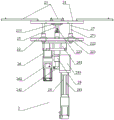
In some embodiments, the lifting and rotating table comprises a rotating upper plate and a rotating lower plate which are coaxially arranged, the rotating upper plate and the rotating lower plate are connected through a first guide mechanism arranged along the vertical direction, a plurality of first brackets are uniformly distributed along the circumferential direction of the rotating upper plate, the rotating lower plate is driven by a first driving mechanism to rotate and drives the rotating upper plate to synchronously rotate through the first guide mechanism, the rotating upper plate is pushed by a first lifting mechanism through a first connecting shaft arranged along the vertical direction to lift, and the first guide mechanism slides relative to the rotating lower plate along the vertical direction.
In some embodiments, the first guide mechanism includes a plurality of first guide shafts arranged along a vertical direction, an upper end of each first guide shaft is fixedly connected with the upper rotating plate, and the lower rotating plate is provided with first guide through holes matched with the first guide shafts.
In some embodiments, the first driving mechanism includes a hollow rotating platform connected to the rotating lower plate and a first motor for driving the hollow rotating platform to rotate.
In some embodiments, the rotating lower plate is provided with a plurality of first buffers matched with the rotating upper plate.
The beneficial effects of this disclosure are: in the using process, the product jig filled with the products is arranged on a first bracket of a lifting rotary workbench at a feeding and discharging station, then the lifting rotary workbench is lifted and rotated to ensure that the product jig is respectively matched with an automatic detection device and a material taking and placing manipulator in sequence, the automatic detection device automatically and accurately and comprehensively detects the products on the product jig, detects whether the appearance, the height and the like of the products are qualified or not, the material taking and placing manipulator puts the qualified products into a packaging material tray on a material receiving and placing device according to the detection result of the automatic detection device, puts the unqualified products into a waste material collecting box, and the empty product jig is replaced at the feeding and discharging station, thereby realizing the automatic detection and packaging of the products, and the operation is simple and convenient, the detection precision is high, the speed is high, the false detection, the omission, the product pollution, the omission and the like are not easy to generate, the lifting rotary worktable rotates after lifting, so that the rotating plane and the operation plane are not in the same plane, collision with other devices around the lifting rotary worktable and the like can not occur in the rotating process of the lifting rotary worktable, the space is more fully utilized, the integral volume of equipment is reduced, the structure is compact and stable, the stability and the reliability are high, the production management and control are convenient, especially under the conditions that products are small, irregular in shape or complex in structure, the production efficiency and the quality and the yield of the products are improved, the production cost is reduced, and the competitiveness of the products is enhanced.
In addition, in the technical solutions of the present disclosure, the technical solutions can be implemented by adopting conventional means in the art, unless otherwise specified.
Drawings
In order to more clearly illustrate the embodiments of the present disclosure or the technical solutions in the prior art, the drawings needed to be used in the description of the embodiments or the prior art will be briefly described below, and it is obvious that the drawings in the following description are some embodiments of the present disclosure, and other drawings can be obtained by those skilled in the art without creative efforts.
Fig. 1 is a perspective view of an automatic detection and packaging all-in-one machine with a protective cover removed according to an embodiment of the disclosure.
Fig. 2 is a perspective view of an automatic detection and packaging all-in-one machine according to an embodiment of the disclosure.
Fig. 3 is a perspective view of a lifting rotary table according to an embodiment of the disclosure.
Fig. 4 is a schematic structural diagram of a lifting rotating table according to an embodiment of the present disclosure.
Fig. 5 is a perspective view of a rotating lower plate according to an embodiment of the present disclosure.
Fig. 6 is a perspective view of a rotating upper plate and a first bracket according to an embodiment of the disclosure.
Fig. 7 is a perspective view of a laser detection device according to an embodiment of the present disclosure.
Fig. 8 is a perspective view of a camera detection device according to an embodiment of the present disclosure.
Fig. 9 is a perspective view of a material receiving tilting disk device according to an embodiment of the present disclosure.
Fig. 10 is a perspective view of a take-off assembly according to one embodiment of the present disclosure.
The reference numerals in the drawings indicate that the frame 1, the work base plate 11, the caster 12 with an adjustment block, the protective cover 13, the safety grating 14, the elevating/lowering/rotating table 2, the rotating upper plate 21, the first bearing 211, the first cover plate 212, the bearing cover 213, the rotating lower plate 22, the first guide through-hole 221, the first guide bushing 222, the first buffer 223, the first avoidance through-hole 224, the second support 225, the first bracket 23, the positioning post 231, the avoidance hole 232, the first elevating mechanism 24, the first electric cylinder 241, the first connecting plate 242, the fixing bracket 243, the first connecting shaft 25, the first driving mechanism 26, the hollow rotating platform 261, the first motor 262, the first guiding mechanism 27, the first guiding shaft 271, the first shaft housing 28, the automatic detection device 3, the laser detection device 31, the laser scanner 311, the first linear motion mechanism 312, the second linear motion mechanism 313, the camera detection device 32, the first camera 321, the material taking and placing manipulator 4, the material receiving swing disc device 5, the upper mounting plate 51, the lower mounting plate 52, the fifth linear motion mechanism 53, the waste collecting box 6, the product jig 7, the material taking assembly 8, the first support 81, the material clamping mechanism 82, the pneumatic clamping jaw 821, the supporting plate 822, the fool-proof block 823, the second lifting mechanism 83 and the first support 9.
Detailed Description
In order to make the objects, technical solutions and advantages of the present disclosure more clearly understood, the present disclosure is further described in detail below with reference to the accompanying drawings and embodiments. It is to be understood that the specific embodiments described herein are merely illustrative of some, but not all, embodiments of the disclosure and are not to be considered as limiting the disclosure. All other embodiments, which can be derived by a person skilled in the art from the embodiments disclosed herein without making any creative effort, shall fall within the protection scope of the present disclosure.
In the description of the present disclosure, it should be noted that the terms "center", "upper", "lower", "left", "right", "vertical", "horizontal", "inner", "outer", "both ends", "both sides", etc., indicate orientations or positional relationships based on the orientations or positional relationships shown in the drawings, and are only for convenience in describing the present disclosure and simplifying the description, but do not indicate or imply that the elements referred to must have a specific orientation or be constructed and operated in a specific orientation, and thus, should not be construed as limiting the present disclosure. Furthermore, the terms "first," "second," "upper," "lower," "primary," "secondary," and the like are used for descriptive purposes only and may be used for purposes of simplicity in more clearly distinguishing between various components and not to indicate or imply relative importance.
In the description of the present disclosure, it is to be noted that, unless otherwise explicitly specified or limited, the terms "mounted," "connected," and "connected" are to be construed broadly, e.g., as meaning either a fixed connection, a removable connection, or an integral connection; can be mechanically or electrically connected; they may be connected directly or indirectly through intervening media, or they may be interconnected between two elements. The specific meaning of the above terms in the present disclosure can be understood in specific instances by those of ordinary skill in the art.
Fig. 1 is a perspective view of an automatic detection and packaging all-in-one machine provided by an embodiment of the disclosure, fig. 2 is a perspective view of the automatic detection and packaging all-in-one machine provided by the disclosure, fig. 3 is a perspective view of a lifting and rotating table provided by the embodiment of the disclosure, fig. 4 is a structural schematic view of the lifting and rotating table provided by the embodiment of the disclosure, fig. 5 is a perspective view of a rotating lower plate provided by the embodiment of the disclosure, fig. 6 is a perspective view of a rotating upper plate and a first bracket provided by the embodiment of the disclosure, fig. 7 is a perspective view of a laser detection device provided by the embodiment of the disclosure, fig. 8 is a perspective view of a camera detection device provided by the embodiment of the disclosure, fig. 9 is a perspective view of a material receiving swing plate device provided by the embodiment of the disclosure, and fig. 10 is a perspective view of a material taking assembly provided by the embodiment of the disclosure.
Example (b):
as shown in fig. 1-10, the automatic detection and packaging integrated machine is mainly used for detecting and packaging products such as CNC (computerized numerical control) workpieces, stamping parts, injection molding parts and the like, and comprises a frame 1, wherein a working bottom plate 11 is usually arranged at the top of the frame 1, a lifting rotary table 2, feeding and discharging stations sequentially arranged along the circumferential direction of the lifting rotary table 2, an automatic detection device 3, a material taking and placing manipulator 4, a material receiving swing disc device 5 and a waste material collecting box 6 matched with the material taking and placing manipulator 4 are arranged on the working bottom plate 11 of the frame 1, a first bracket 23 for placing a product jig 7 is arranged on the lifting rotary table 2 along the circumferential direction, according to specific circumstances, the first bracket 23 can be one, two or more, and the unloading station is used for settling and changing the product tool 7 on the first bracket 23, and the product tool 7 is usually evenly distributed with a plurality of positioning grooves for settling the product.
The automatic detection device 3 comprises a laser detection device 31 and at least one camera detection device 32, the number of the camera detection devices 32 is determined according to specific conditions, the lifting rotary worktable 2 can drive the product jig 7 to be sequentially matched with the laser detection device 31 and the camera detection device 32 respectively through lifting and rotating, the laser detection device 31 and the camera detection device 32 can accurately and comprehensively detect the appearance, height and size and the like of a product on the product jig 7, and even if the product is small, irregular in shape or complex in structure, the product can be accurately and comprehensively detected, the detection precision is high, and the stability and the reliability are high.
The laser detection device 31 comprises a laser scanner 311 and a first linear motion mechanism 312 and a second linear motion mechanism 313 which drive the laser scanner 311 to move along the horizontal transverse direction and the longitudinal direction, the camera detection device 32 comprises a first camera 321 and a third linear motion mechanism 322 and a fourth linear motion mechanism 323 which drive the first camera 321 to move along the horizontal transverse direction and the longitudinal direction, two directions which are perpendicular to each other in the horizontal transverse direction and the longitudinal direction, namely the horizontal direction, the number and the position arrangement of the laser scanner 311 and the first camera 321 are determined according to specific conditions, the first linear motion mechanism 312 drives the laser scanner 311 to move linearly, the second linear motion mechanism 313 drives the first linear motion mechanism 312 and the laser scanner 311 to move linearly integrally, the third linear motion mechanism 322 drives the first camera 321 to move linearly, and the fourth linear motion mechanism 323 drives the third linear motion mechanism 322 and the first camera 321 to move linearly integrally, therefore, the product can be detected more accurately and comprehensively.
The first linear motion mechanism 312, the second linear motion mechanism 313, the third linear motion mechanism 322, and the fourth linear motion mechanism 323 can adopt a cylinder, an oil cylinder, an electric cylinder, a linear module, and the like, and can generally adopt a linear module, so that the motion precision is high and stable, and the control is convenient. The laser scanner 311 may also be a 3D scanner, a three-dimensional intelligent sensor, an optical fiber displacement sensor, etc., and the laser detection device 31 can detect a product with an irregular shape or a complex structure more accurately and comprehensively through processing such as laser scanning. The first camera 321 is typically a CCD camera that is small, light, not affected by magnetic fields, and resistant to vibration and impact.
The laser scanner 311 and the first camera 321 are generally connected to the first linear motion mechanism 312 and the third linear motion mechanism 322 through a bracket, and sliding tables, such as a cross sliding table or a three-axis sliding table, which are matched with the laser scanner 311 and the first camera 321 and are arranged in a vertical direction, may be respectively disposed on the corresponding brackets, so that the height positions of the laser scanner 311 and the first camera 321 can be conveniently adjusted through the sliding tables, thereby better detecting the product. The corresponding supports can also be respectively provided with light sources which are correspondingly matched with the laser scanner 311 and the first camera 321, such as a coaxial light source, an annular light source, a backlight source and the like, so that a better detection environment can be provided through the light sources, and the detection precision is higher.
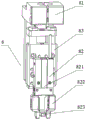
The material taking and placing manipulator 4 can be a six-axis manipulator, a swing arm manipulator and the like, the front end of the material taking and placing manipulator 4 is provided with a material taking assembly 8, and the material taking assembly 8 can adopt a vacuum suction mode, a clamping mode and the like according to different products. For a generally annular product, the material taking assembly 8 comprises a first support 81, a material clamping mechanism 82 and a second lifting mechanism 83 for driving the material clamping mechanism 82 to move up and down are arranged on the first support 81, and the second lifting mechanism 83 pushes the material clamping mechanism 82 to move up and down so as to clamp and place the corresponding product. The second lifting mechanism 83 can adopt the modes of an air cylinder, an oil cylinder, an electric cylinder, a linear module and the like, and generally adopts the mode of the air cylinder, so that the structure is simple and compact, the installation and the maintenance are convenient, and the safety, the environmental protection and the like are realized.
The material clamping mechanism 82 comprises a pneumatic clamping jaw 821, the pneumatic clamping jaw 821 is connected with the second lifting mechanism 83, two clamping jaws of the pneumatic clamping jaw 821 are respectively connected with a supporting plate 822, the two supporting plates 822 can be inserted into inner holes of annular products, and the pneumatic clamping jaw 821 moves along the horizontal direction by pushing the two supporting plates 822 to enable the two supporting plates 822 to stretch or loosen the products, so that corresponding products can be clamped and placed. The pneumatic gripper 821, also known as a pneumatic finger or a pneumatic gripper finger, is an actuating device for gripping or grabbing a workpiece by using compressed air as power, and can effectively improve the production efficiency and the safety of work. In addition, to some irregularly shaped, asymmetric products, the product need be put according to certain direction in receiving material balance device 5, second elevating system 83 can also be provided with press from both sides material mechanism 82 matched with prevent slow-witted piece 823, prevent that slow-witted piece 823 can guarantee to place the product according to certain direction, prevent that the product direction from putting reversely, and is safer, reliable.
The material receiving swing plate device 5 comprises an upper mounting plate 51 and a lower mounting plate 52 which are used for placing a packaging material plate, a plurality of cavities used for placing products are usually uniformly distributed on the packaging material plate, the upper mounting plate 51 is located above the lower mounting plate 52, the upper mounting plate 51 and the lower mounting plate 52 are respectively driven by a fifth linear motion mechanism 53, the two fifth linear motion mechanisms 53 are arranged side by side, the two fifth linear motion mechanisms 53 can drive the upper mounting plate 51 and the lower mounting plate 52 to respectively correspond to a product placing station and a packaging material plate replacing station, and the movement of the upper mounting plate 51 and the movement of the lower mounting plate 52 are not interfered with each other. In the use, go up the packing charging tray on the mounting panel 51 and place the station with the product and carry out the product when placing, fifth rectilinear movement mechanism can drive down mounting panel 52 and remove the packing charging tray and change the station and carry out the change of packing charging tray, packing charging tray on the lower mounting panel 52 is placing the station with the product and carry out the product when placing, fifth rectilinear movement mechanism can drive upper mounting panel 51 equally and remove the packing charging tray and change the station and carry out the change of packing charging tray, thereby the placing of product and the change mutual noninterference of packing charging tray, it is more convenient to operate, efficiency is higher.
Go up on mounting panel 51 and be provided with a plurality of locating pieces that are used for the location packing material dish on the mounting panel, the locating piece of four directions encloses into the interval that is used for the location to place the packing material dish usually, simple structure, convenient operation, stability is good. The fifth linear motion mechanism 53 can adopt a cylinder, an oil cylinder, an electric cylinder, a screw rod driving mechanism, a linear module and the like, and generally adopts a cylinder form, especially a rodless cylinder or a rodless cylinder with a guide rod, so that the structure is simpler and more compact, the motion is more stable, the installation and the maintenance are more convenient, the installation space is saved, and the safety, the environmental protection and the like are realized. In addition, guide mechanisms, such as linear bearing guide rods, linear slide rails, etc., may be provided to be linearly moved in cooperation with the upper mounting plate 51 and the lower mounting plate 52, respectively.
The lifting and rotating workbench 2 comprises a rotating upper plate 21 and a rotating lower plate 22 which are coaxially arranged, the rotating upper plate 21 and the rotating lower plate 22 are connected through a first guide mechanism 27 arranged along the vertical direction, the first guide mechanism 27 is usually fixedly connected with the rotating upper plate 21, the first guide mechanism 27 is in sliding connection with the rotating lower plate 22, a plurality of first brackets 23 are uniformly distributed along the circumferential direction of the rotating upper plate 21, the number of the first brackets 23 can be one, two or more according to specific requirements, the rotating lower plate 22 is driven by a first driving mechanism 26 to rotate, the rotating lower plate 22 drives the rotating upper plate 21 to synchronously rotate through the first guide mechanism 27, the rotating upper plate 21 is driven by a first lifting mechanism 24 to lift through a first connecting shaft 25 arranged along the vertical direction, the first guide mechanism 27 slides relative to the rotating lower plate 22 along the vertical direction, the first driving mechanism 26 is driven and installed on the working bottom plate 11 of the rack 1, the first guide mechanism 27 is located below the work base 11. When in use, after the product jig 7 filled with products is placed on the first bracket 23, the first lifting mechanism 24 pushes the rotating upper plate 21 to lift through the first connecting shaft 25, the first guide mechanism 27 slides relative to the rotating lower plate 22 along the vertical direction, then the first driving mechanism 26 drives the rotating lower plate 22 to rotate, the rotating lower plate 22 drives the rotating upper plate 21 to rotate synchronously through the first guide mechanism 27, when the product jig 7 rotated on the first bracket 23 corresponds to the loading and unloading station, the laser detection device 31, the camera detection device 32, the material taking and placing manipulator 4 and the like, the first lifting mechanism 24 drives the rotating upper plate 21 to descend to a proper position through the first connecting shaft 25 so as to perform corresponding processing on the products of the product jig 7, the lifting and rotating of the rotating upper plate 21 can be realized through the first driving mechanism 26 and the first lifting mechanism 24, so that the rotating plane of the rotating upper plate 21 is not in the same plane with the operating plane, the rotary upper plate 21 can freely and safely rotate, and cannot collide with other devices around the rotary upper plate, so that the space is more fully utilized, the overall size of the equipment is reduced, the structure is simple and compact, the operation such as installation and adjustment is convenient, the motion is stable and reliable, the overall processing precision and the processing quality of the equipment can be improved, the practicability is high, and the application and the development of the equipment are improved.
Be provided with on first bracket 23 and be used for with product tool 7 matched with reference column 231 and dodge hole 232, be convenient for more accurately, stably, settle corresponding product tool 7 reliably through reference column 231 and dodge hole 232, easy operation, convenience.
The first guiding mechanism 27 comprises a plurality of first guiding shafts 271 arranged along the vertical direction, the upper ends of the first guiding shafts 271 are fixedly connected with the rotating upper plate 21, the rotating lower plate 22 is provided with first guiding through holes 221 matched with the first guiding shafts 271, when the rotating upper plate 21 is pushed to lift by the first lifting mechanism 24 through the first connecting shaft 25, the first guiding shafts 271 synchronously slide up and down along the first guiding through holes 221 on the rotating lower plate 22, the structure is simple, the movement is stable, and the precision is high. Further, the first guide through hole 221 is provided with a first guide sleeve 222, such as a shaft sleeve, an oilless shaft sleeve, a linear bearing, etc., which is matched with the first guide shaft 271, so that the movement is more stable and the precision is higher.
The first guide shafts 271 are usually plural, and the plural first guide shafts 271 are arranged along the circumferential direction of the rotating upper plate 21, so that the lifting motion of the rotating upper plate 21 is more stable, the integral structure of the rotating upper plate 21 and the rotating lower plate 22 is more stable, and the rotating upper plate 21 can better rotate synchronously with the rotating upper plate 21.
Be provided with a plurality of first buffers 223 with rotatory upper plate 21 matched with on rotatory hypoplastron 22, first buffer 223 is installed on rotatory hypoplastron 22 through second support 225, the quantity and the position of first buffer 223 are according to the size of rotatory upper plate 21, specific situations such as shape are decided, first buffer 223 can adopt elastic buffer block, oil pressure buffer, spring damper, polyurethane buffer etc, the oil pressure buffer that has advantages such as reduction vibrations and noise usually adopts, first buffer 223 can carry out the buffering protection to rotatory upper plate 21, thereby it is more stable, reliable, the life of this workstation has been improved.
The first lifting mechanism 24 can be a cylinder, an oil cylinder, an electric cylinder, a linear module, etc. The first lifting mechanism 24 adopts a first electric cylinder 241 arranged along the vertical direction, the first electric cylinder 241 is connected with the lower end of the first connecting shaft 25 through a first connecting plate 242, the first electric cylinder 241 is usually installed on the working bottom plate 11 of the frame 1 of the corresponding processing equipment through a fixing frame 243, and the electric cylinder integrates a servo motor and a lead screw, so that high-precision straight line can be realized, the operation and maintenance are simple, the installation and configuration are very flexible, and the electric cylinder has the advantages of low noise, energy conservation, cleanness, high rigidity, impact resistance, super long service life and the like.
The first driving mechanism 26 includes a hollow rotating platform 261 connected to the rotating lower plate 22 and a first motor 262 for driving the hollow rotating platform 261 to rotate, the rotating disc of the hollow rotating platform 261 is of a hollow structure, the rotating disc of the hollow rotating platform is supported by a set of precise crossed roller bearings so that the rotating disc can bear various moments such as radial, axial and overturning, the first motor 262 is connected to the side of the rotating disc, the first motor 262 can be a servo motor, a stepping motor and the like, the outer ring of the crossed roller bearing is connected to the rotating lower plate 22, the first motor 262 drives the outer ring of the crossed roller bearing to rotate through gear transmission and the like, so as to drive the rotating lower plate 22 to rotate, and the efficiency, the precision, the rigidity, the bearing stability and the like are high.
In order to facilitate the lifting and rotating of the rotating upper plate 21, etc., the first connecting shaft 25 passes through the central hole of the hollow rotating platform 261 and is coaxial with the central hole of the hollow rotating platform 261, that is, the first connecting shaft 25 is coaxial with the central hole of the hollow rotating platform 261, the rotating upper plate 21 and the rotating lower plate 22, the center of the rotating lower plate 22 is provided with a first avoiding through hole 224 matched with the first connecting shaft 25, and the upper end of the first connecting shaft 25 is generally axially fixed with the rotating upper plate 21 and rotates relatively in the circumferential direction, so that the structure is more compact and stable. In order to facilitate the relative rotation of the upper end of the first connecting shaft 25 and the circumferential direction of the rotating upper plate 21, a first bearing 211 matched with the first connecting shaft 25 and a bearing cover 213 for fixing the first bearing 211 are arranged on the rotating upper plate 21, a first cover plate 212 matched with the first bearing 211 is further arranged at the top of the first connecting shaft 25, and the first cover plate 212 can axially fix the first connecting shaft 25 and the rotating upper plate 21.
Still be provided with first axle sleeve 28 between the centre bore of cavity revolving platform 261 and the first connecting axle 25, when rotatory upper plate 21 goes up and down, first connecting axle 25 slides from top to bottom along first axle sleeve 28 is synchronous, cavity revolving platform 261 and first axle sleeve 28 are installed on the work bottom plate 11 of frame 1 usually, be convenient for first connecting axle 25 better to cooperate with the centre bore of cavity revolving platform 261 through first axle sleeve 28, and also can reduce the diameter and the weight of first connecting axle 25, and materials are saved, and the cost etc..
Can also set up the first support 9 of placing product tool 7 on the work bottom plate 11 of frame 1, go up the unloading station, laser detection device 31, camera detection device 32 and get and expect that manipulator 4 punishment do not is provided with first support 9, 2 rotatory to respectively with last unloading station of rotatory workstation, laser detection device 31, camera detection device 32 and get when expecting the corresponding position of manipulator 4, 2 drive product tool of rotatory workstation 7 downstream, product tool 7 on the first bracket 23 can be placed automatically on first support 9, and is more stable, and reliable.
The bottom of frame 1 can be provided with the area and transfer whole block truckle 12, sets up area and transfer whole block truckle 12 respectively at four extreme angle departments of frame 1 bottom usually, is convenient for move equipment wholely and leveling through area and transfer whole block truckle 12, and convenient operation has improved the flexibility and the stability of equipment. Still be provided with protection casing 13 on the frame 1, lifting and drop rotating table 2, automatic checkout device 3, get and put material manipulator 4, receive material balance device 5, garbage collection box 6 etc. and all be located protection casing 13 to it is safer, reliable. The protective cover 13 can be further provided with a plurality of layers of warning lamps, the plurality of layers of warning lamps are also called multilayer signal lamps, indicator lamps, industrial signal lamps or tower lamps, are generally used for industrial production equipment and transmission control operation, mainly transmit the equipment state or the transmission state to machine operators, technicians, production managers and factory personnel in a visual and sound signal mode, and improve the safety of the equipment by arranging the plurality of layers of warning lamps. Safety gratings 14 can be further arranged on two sides of the feeding and discharging station, misoperation can be prevented when the product jig 7 is replaced, and the safety gratings 14 can also be arranged on the packaging material tray replacing station of the material receiving swing tray device 5, so that the material receiving swing tray device is safer and more reliable.
In the using process, the product jigs 7 filled with products are arranged on the first bracket 23 of the lifting rotary worktable 2 at the loading and unloading station, then the lifting and rotating workbench 2 is lifted and rotated to ensure that the product jig 7 is respectively matched with the laser detection device 31, the camera detection device 32 and the material taking and placing manipulator 4 in sequence, the laser detection device 31 and the camera detection device 32 can automatically and accurately and comprehensively detect the products on the product jig 7, detect whether the appearance, the height and the size of the products are qualified or not, according to the detection result of the automatic detection device 3, the material taking and placing manipulator 4 puts the qualified products into the packaging material tray on the material receiving tray placing device 5 through the material taking component 8, and put unqualified product into the garbage collection box 6, empty product tool 7 is changed at the material loading and unloading station, and this process is circulated, thereby realizes automated inspection and packing of product.
Compared with the prior art, the advantage of this disclosure has: the automatic accurate and comprehensive detection can be automatically carried out on products through the laser detection device 31 and the camera detection device 32, the detected products can be automatically classified, packaged and collected through the material taking and placing manipulator 4, the material taking assembly 8, the material receiving swing disc device 5 and the waste material collecting box 6, the automatic detection and packaging of the products are realized, the operation is simple and convenient, the detection precision is high, the speed is high, the false detection, the omission, the product pollution, the omission and the like are not easy to generate, the labor intensity is low, the labor and the time are effectively saved, and the lifting and rotating workbench 2 rotates after being lifted, so that the rotating plane is not in the same plane with the operation plane, the collision and the like with other devices around the lifting and rotating workbench 2 can not be generated in the rotating process, the space is more fully utilized, the integral volume of the equipment is reduced, the structure is compact and stable, and the stability and the reliability are high, the production management and control are convenient, especially under the conditions that the product is small, irregular in shape or complex in structure, the production efficiency, the quality and the yield of the product are improved, the production cost is reduced, and the competitiveness of the product is enhanced. In addition, at last unloading station, can also be equipped with suitable manipulator etc. so that realize the automatic unloading of going up of product tool 7, production efficiency is higher.
The foregoing is directed to embodiments of the present disclosure, which are provided for illustration only and not for limitation, and it is understood that modifications and substitutions may be made by those skilled in the art without departing from the spirit of the disclosure and all such modifications and substitutions are to be considered within the scope of the appended claims. In this case all the details may be replaced with equivalent elements, and the materials, shapes and dimensions may be any.
Claims (10)
1. The automatic detection and packaging integrated machine is characterized by comprising a rack (1), wherein a lifting rotary workbench (2), a feeding and discharging station, an automatic detection device (3), a feeding and discharging manipulator (4) and a receiving and placing tray device (5) and a waste collection box (6) which are sequentially arranged along the circumferential direction of the lifting rotary workbench (2) as well as a receiving and placing manipulator (4) matched with the feeding and discharging manipulator (4) are arranged on the rack (1), the lifting rotary workbench (2) is provided with a first bracket (23) for placing a product jig (7) along the circumferential direction, the lifting rotary workbench (2) can drive the product jig (7) to lift and rotate so that the product jig (7) is sequentially matched with the feeding and discharging station, the automatic detection device (3) and the feeding and discharging manipulator (4) correspondingly, and the automatic detection device (3) can automatically detect products on the product jig (7), the material taking and placing manipulator (4) can place products into the material receiving and placing tray device (5) or the waste collecting box (6) according to detection results.
2. The machine according to claim 1, wherein the automatic detection means (3) comprise laser detection means (31) and at least one camera detection means (32).
3. The machine according to claim 2, wherein the laser detection device (31) comprises a laser scanner (311) and a first linear motion mechanism (312) and a second linear motion mechanism (313) for driving the laser scanner (311) to move horizontally in the transverse direction and the longitudinal direction, and the camera detection device (32) comprises a first camera (321) and a third linear motion mechanism (322) and a fourth linear motion mechanism (323) for driving the first camera (321) to move horizontally in the transverse direction and the longitudinal direction.
4. The all-in-one machine for automatically detecting and packaging as claimed in claim 1, wherein a material taking assembly (8) is arranged at the front end of the material taking and placing manipulator (4).
5. The all-in-one machine for automatically detecting and packaging as claimed in claim 4, wherein the material taking assembly (8) comprises a first support (81), and a material clamping mechanism (82) and a second lifting mechanism (83) for driving the material clamping mechanism (82) to move up and down are arranged on the first support (81).
6. The all-in-one machine for automatically detecting and packaging materials as claimed in claim 1, wherein the material receiving and swinging device (5) comprises an upper mounting plate (51) and a lower mounting plate (52) for placing a packaging material tray, the upper mounting plate (51) is positioned above the lower mounting plate (52), the upper mounting plate (51) and the lower mounting plate (52) are respectively driven by a fifth linear motion mechanism (53), the two fifth linear motion mechanisms (53) are arranged side by side, and the two fifth linear motion mechanisms (53) can drive the upper mounting plate (51) and the lower mounting plate (52) to respectively correspond to a product placing station and a packaging material tray replacing station.
7. The automated inspection and packaging kiosk according to any of claims 1-6, it is characterized in that the lifting rotary worktable (2) comprises a rotary upper plate (21) and a rotary lower plate (22) which are coaxially arranged, the rotary upper plate (21) is connected with the rotary lower plate (22) through a first guide mechanism (27) arranged along the vertical direction, a plurality of first brackets (23) are uniformly distributed along the circumferential direction of the rotary upper plate (21), the rotating lower plate (22) is driven by a first driving mechanism (26) to rotate and drives the rotating upper plate (21) to rotate synchronously through the first guide mechanism (27), the rotary upper plate (21) is pushed by a first lifting mechanism (24) through a first connecting shaft (25) arranged along the vertical direction to lift, and the first guide mechanism (27) slides relative to the rotary lower plate (22) along the vertical direction.
8. The all-in-one machine for automatic detection and packaging as claimed in claim 7, wherein the first guide mechanism (27) comprises a plurality of first guide shafts (271) arranged along a vertical direction, the upper ends of the first guide shafts (271) are fixedly connected with the upper rotating plate (21), and the lower rotating plate (22) is provided with first guide through holes (221) matched with the first guide shafts (271).
9. The machine according to claim 7, wherein the first drive mechanism (26) comprises a hollow rotary platform (261) connected to the rotary lower plate (22) and a first motor (262) for driving the hollow rotary platform (261) in rotation.
10. The all-in-one machine for automatically detecting and packaging as claimed in claim 7, wherein the rotating lower plate (2) is provided with a plurality of first buffers (23) matched with the rotating upper plate (1).
Priority Applications (1)
| Application Number | Priority Date | Filing Date | Title |
|---|---|---|---|
| CN202010318194.5A CN111389752A (en) | 2020-04-21 | 2020-04-21 | Automatic detect packaging all-in-one machine |
Applications Claiming Priority (1)
| Application Number | Priority Date | Filing Date | Title |
|---|---|---|---|
| CN202010318194.5A CN111389752A (en) | 2020-04-21 | 2020-04-21 | Automatic detect packaging all-in-one machine |
Publications (1)
| Publication Number | Publication Date |
|---|---|
| CN111389752A true CN111389752A (en) | 2020-07-10 |
Family
ID=71417010
Family Applications (1)
| Application Number | Title | Priority Date | Filing Date |
|---|---|---|---|
| CN202010318194.5A Pending CN111389752A (en) | 2020-04-21 | 2020-04-21 | Automatic detect packaging all-in-one machine |
Country Status (1)
| Country | Link |
|---|---|
| CN (1) | CN111389752A (en) |
Cited By (6)
| Publication number | Priority date | Publication date | Assignee | Title |
|---|---|---|---|---|
| CN111964592A (en) * | 2020-08-28 | 2020-11-20 | 苏州天准科技股份有限公司 | Detection equipment and electronic product part detection system |
| CN113044549A (en) * | 2021-02-01 | 2021-06-29 | 苏州领裕电子科技有限公司 | Examine all-in-one of packing entirely |
| CN113305022A (en) * | 2021-05-19 | 2021-08-27 | 福益柯汽车系统(上海)有限公司 | High-efficient accurate type test fixture of product length foot |
| CN113532282A (en) * | 2021-06-17 | 2021-10-22 | 深圳市骏创科技有限公司 | Automatic change detection, packing integrated form production facility |
| CN114939548A (en) * | 2022-05-16 | 2022-08-26 | 歌尔股份有限公司 | Automatic sorting mechanism |
| CN115055962A (en) * | 2022-07-04 | 2022-09-16 | 新昌县精艺轴承有限公司 | Automatic assembling machine for retainer |
-
2020
- 2020-04-21 CN CN202010318194.5A patent/CN111389752A/en active Pending
Cited By (9)
| Publication number | Priority date | Publication date | Assignee | Title |
|---|---|---|---|---|
| CN111964592A (en) * | 2020-08-28 | 2020-11-20 | 苏州天准科技股份有限公司 | Detection equipment and electronic product part detection system |
| CN113044549A (en) * | 2021-02-01 | 2021-06-29 | 苏州领裕电子科技有限公司 | Examine all-in-one of packing entirely |
| CN113305022A (en) * | 2021-05-19 | 2021-08-27 | 福益柯汽车系统(上海)有限公司 | High-efficient accurate type test fixture of product length foot |
| CN113532282A (en) * | 2021-06-17 | 2021-10-22 | 深圳市骏创科技有限公司 | Automatic change detection, packing integrated form production facility |
| CN113532282B (en) * | 2021-06-17 | 2023-08-11 | 深圳市骏创科技有限公司 | Automatic change detection, packing integrated production facility |
| CN114939548A (en) * | 2022-05-16 | 2022-08-26 | 歌尔股份有限公司 | Automatic sorting mechanism |
| CN114939548B (en) * | 2022-05-16 | 2023-12-22 | 歌尔股份有限公司 | Automatic sorting mechanism |
| CN115055962A (en) * | 2022-07-04 | 2022-09-16 | 新昌县精艺轴承有限公司 | Automatic assembling machine for retainer |
| CN115055962B (en) * | 2022-07-04 | 2024-02-20 | 新昌县精艺轴承有限公司 | Automatic assembling machine for retainer |
Similar Documents
| Publication | Publication Date | Title |
|---|---|---|
| CN111389752A (en) | Automatic detect packaging all-in-one machine | |
| CN212370612U (en) | Automatic detect packaging all-in-one machine | |
| CN111318477A (en) | Multi-threaded hole automatic detection machine | |
| CN212364117U (en) | Multi-directional appearance detection equipment | |
| CN111532487A (en) | Multi-station detection packaging equipment | |
| CN111591754B (en) | Shaft part conveying robot | |
| CN108942984A (en) | A kind of manipulator of intelligent robot | |
| CN109754695B (en) | Teaching equipment for intelligent operation of product detection and sorting informatization | |
| CN207139398U (en) | Multiple-station rotation lifting combination feeding storage arrangement | |
| CN111774329A (en) | Visual detection equipment for elastic sheet | |
| CN212666088U (en) | Automatic material taking and placing device | |
| CN212370626U (en) | Multi-threaded hole automatic detection machine | |
| CN113375630A (en) | Detection apparatus suitable for industrial robot | |
| CN112589504A (en) | Lathe for manufacturing numerical control automatic production mechanical arm | |
| CN214642727U (en) | Special honing machine of rotation multistation connecting rod | |
| CN114047194A (en) | Intelligent robot production detection device for manufacturing industry | |
| CN212349532U (en) | Visual detection equipment for elastic sheet | |
| CN212667785U (en) | Multi-station detection packaging equipment | |
| CN115971086A (en) | Double-turntable type intelligent screw defect full-detection equipment | |
| CN216679093U (en) | Gear shaft coaxiality detection device | |
| CN214776890U (en) | Examine all-in-one of packing entirely | |
| CN213620455U (en) | Workpiece front and back recognition split charging equipment | |
| CN114670406A (en) | Fan impeller intelligent detection equipment | |
| CN211254349U (en) | Rotary manipulator | |
| CN112828759A (en) | Special honing machine of rotation multistation connecting rod |
Legal Events
| Date | Code | Title | Description |
|---|---|---|---|
| PB01 | Publication | ||
| PB01 | Publication | ||
| SE01 | Entry into force of request for substantive examination | ||
| SE01 | Entry into force of request for substantive examination |