CN111361995B - Feeding device and method - Google Patents
Feeding device and method Download PDFInfo
- Publication number
- CN111361995B CN111361995B CN202010218145.4A CN202010218145A CN111361995B CN 111361995 B CN111361995 B CN 111361995B CN 202010218145 A CN202010218145 A CN 202010218145A CN 111361995 B CN111361995 B CN 111361995B
- Authority
- CN
- China
- Prior art keywords
- lifting
- assembly
- material receiving
- translation
- receiving
- Prior art date
- Legal status (The legal status is an assumption and is not a legal conclusion. Google has not performed a legal analysis and makes no representation as to the accuracy of the status listed.)
- Active
Links
Images


Classifications
-
- B—PERFORMING OPERATIONS; TRANSPORTING
- B65—CONVEYING; PACKING; STORING; HANDLING THIN OR FILAMENTARY MATERIAL
- B65G—TRANSPORT OR STORAGE DEVICES, e.g. CONVEYORS FOR LOADING OR TIPPING, SHOP CONVEYOR SYSTEMS OR PNEUMATIC TUBE CONVEYORS
- B65G47/00—Article or material-handling devices associated with conveyors; Methods employing such devices
- B65G47/74—Feeding, transfer, or discharging devices of particular kinds or types
- B65G47/90—Devices for picking-up and depositing articles or materials
- B65G47/91—Devices for picking-up and depositing articles or materials incorporating pneumatic, e.g. suction, grippers
- B65G47/912—Devices for picking-up and depositing articles or materials incorporating pneumatic, e.g. suction, grippers provided with drive systems with rectilinear movements only
-
- B—PERFORMING OPERATIONS; TRANSPORTING
- B65—CONVEYING; PACKING; STORING; HANDLING THIN OR FILAMENTARY MATERIAL
- B65G—TRANSPORT OR STORAGE DEVICES, e.g. CONVEYORS FOR LOADING OR TIPPING, SHOP CONVEYOR SYSTEMS OR PNEUMATIC TUBE CONVEYORS
- B65G47/00—Article or material-handling devices associated with conveyors; Methods employing such devices
- B65G47/74—Feeding, transfer, or discharging devices of particular kinds or types
- B65G47/90—Devices for picking-up and depositing articles or materials
- B65G47/91—Devices for picking-up and depositing articles or materials incorporating pneumatic, e.g. suction, grippers
- B65G47/918—Devices for picking-up and depositing articles or materials incorporating pneumatic, e.g. suction, grippers with at least two picking-up heads
Abstract
The invention relates to the technical field of material handling, in particular to a feeding device and a feeding method. The feeding device provided by the invention comprises a lifting material receiving mechanism and an opening and closing material receiving mechanism, wherein the lifting material receiving mechanism comprises a lifting driving assembly and a lifting material receiving assembly, and a driving end of the lifting driving assembly is connected with the lifting material receiving assembly and can drive the lifting material receiving assembly to lift along the vertical direction; the material receiving mechanism that opens and shuts includes translation drive assembly and translation and connects the material subassembly, and at least two material receiving mechanism that opens and shuts set up along the week side of lift receiving mechanism, and translation drive assembly's drive end connects the material subassembly with the translation and is connected and can drive the translation and connect the material subassembly to remove along the horizontal direction to make at least two translations connect the material subassembly to be close to each other in order to accept the material, or make at least two translations connect the material subassembly to keep away from each other so that the lift connects the material subassembly to rise. This loading attachment can realize two materials of a material loading, improves the material loading efficiency of material.
Description
Technical Field
The invention relates to the technical field of material handling, in particular to a feeding device and a feeding method.
Background
At present, the material is loaded by a manipulator in a material loading mode. When the material is a substrate, the feeding device generally only receives one substrate, so that the manipulator can only carry one substrate at a time, and the feeding efficiency is low.
Therefore, a feeding device is needed to solve the above problems.
Disclosure of Invention
The invention aims to provide a feeding device, which solves the problem of low feeding efficiency of the feeding device in the prior art.
The invention also aims to provide a feeding method, and the feeding device can improve the material feeding efficiency.
In order to realize the purpose, the following technical scheme is provided:
in one aspect, a feeding device is provided, including:
the lifting material receiving mechanism comprises a lifting driving assembly and a lifting material receiving assembly, wherein the driving end of the lifting driving assembly is connected with the lifting material receiving assembly and can drive the lifting material receiving assembly to lift along the vertical direction;
receiving mechanism opens and shuts, including translation drive assembly and translation material receiving assembly, at least two receiving mechanism edge opens and shuts the week side setting of receiving mechanism goes up and down, translation drive assembly's drive end with the translation material receiving assembly is connected and can drives the translation material receiving assembly removes along the horizontal direction to make at least two the translation material receiving assembly is close to each other in order to accept the material, or makes at least two the translation material receiving assembly keeps away from each other so that the material receiving assembly goes up and down to rise.
As loading attachment's preferred scheme, the lift meets material subassembly includes:
the supporting platform is fixedly connected with the driving end of the synchronous lifter;
the first suction nozzles are installed on the supporting platform and used for adsorbing and bearing materials.
As the preferred scheme of loading attachment, supporting platform includes body frame and support bar, many the parallel interval of support bar sets up on the body frame, the body frame with all install on the support bar first suction nozzle.
As a preferable aspect of the feeding device, the lifting drive assembly includes:
a motor;
the synchronous lifter is connected with the driving end of the motor, the driving end of the synchronous lifter is connected with the lifting material receiving assembly, and the motor can drive the driving end of the synchronous lifter to lift along the vertical direction so as to enable the lifting material receiving assembly to lift.
As a preferable scheme of the feeding device, the translation driving assembly comprises a linear driver, and a driving end of the linear driver is connected with the translation material receiving assembly so as to drive the translation material receiving assembly to move along the horizontal direction.
As a preferable scheme of the feeding device, the linear actuator is an air cylinder.
As a preferable scheme of the feeding device, the translation driving assembly further comprises:
the guide rail is parallel to the moving direction of the translation material receiving assembly;
the sliding block is in sliding fit with the guide rail and is connected with the translational material receiving assembly, so that the translational material receiving assembly moves along the guide rail.
As loading attachment's preferred scheme, the translation meets the material subassembly includes:
the support frame is fixedly connected with the driving end of the linear driver;
and the second suction nozzles are arranged on the supporting frame and are used for adsorbing and bearing materials.
As a preferable scheme of the feeding device, the support frame includes:
the bottom surface of the bottom plate is fixedly connected with the driving end of the linear driver;
the support arm, including perpendicular first support arm and the second support arm that sets up, first support arm with the top surface fixed connection of bottom plate, the second support arm is used for the installation the second suction nozzle, it is a plurality of the parallel interval of support arm sets up on the bottom plate.
As a preferred scheme of the feeding device, the number of the opening and closing material receiving mechanisms is two, the two opening and closing material receiving mechanisms are symmetrically arranged on two sides of the lifting material receiving mechanism along the X direction, the two translation material receiving assemblies can approach each other along the X direction to receive materials, or the two translation material receiving assemblies can separate from each other along the X direction to avoid the lifting material receiving assemblies; or
The quantity of the material receiving mechanisms that open and shut is four, wherein two the material receiving mechanisms that open and shut set up along X direction symmetry lift material receiving mechanisms's both sides, two material receiving mechanisms that open and shut set up along Y direction symmetry lift material receiving mechanisms's both sides, four translation material receiving component can be close to each other in order to accept the material, or four translation material receiving component can keep away from each other in order to dodge material receiving component goes up and down.
In another aspect, a feeding method is provided, which is based on the feeding device, and includes the following steps:
the translational material receiving components are far away from each other;
lifting the lifting material receiving assembly to receive a first material, and then lowering the lifting material receiving assembly to the original position;
enabling the translational material receiving assemblies to approach each other to receive a second piece of material;
the manipulator grabs the second piece of material on the translational receiving component, then the translational receiving component moves in the horizontal plane, and at least two translational receiving components are far away from each other to avoid the lifting receiving component;
and the lifting material receiving assembly rises, and the manipulator picks the first material on the lifting material receiving assembly.
Compared with the prior art, the invention has the beneficial effects that:
the feeding device provided by the invention comprises a lifting material receiving mechanism and an opening and closing material receiving mechanism, wherein the lifting material receiving mechanism comprises a lifting driving assembly and a lifting material receiving assembly, and a driving end of the lifting driving assembly is connected with the lifting material receiving assembly and can drive the lifting material receiving assembly to lift along the vertical direction; the material receiving mechanism that opens and shuts includes translation drive assembly and translation and connects the material subassembly, and at least two material receiving mechanism that opens and shuts set up along the week side of lift receiving mechanism, and translation drive assembly's drive end connects the material subassembly with the translation and is connected and can drive the translation and connect the material subassembly to remove along the horizontal direction to make at least two translations connect the material subassembly to be close to each other in order to accept the material, or make at least two translations connect the material subassembly to keep away from each other so that the lift connects the material subassembly to rise. During the material loading, the manipulator snatchs the material on the receiving mechanism that opens and shuts earlier, then opens the receiving mechanism that opens and shuts so that the rising is located the material on the receiving mechanism that goes up and down to make the manipulator snatch the material on the receiving mechanism that goes up and down, thereby can improve material loading efficiency.
According to the feeding method provided by the invention, the feeding device is adopted, two pieces of materials can be fed at one time, and the material feeding efficiency can be improved.
Drawings
In order to more clearly illustrate the technical solutions in the embodiments of the present invention, the drawings used in the description of the embodiments of the present invention will be briefly described below, and it is obvious that the drawings in the following description are only some embodiments of the present invention, and for those skilled in the art, other drawings can be obtained according to the contents of the embodiments of the present invention and the drawings without creative efforts.
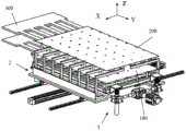
Fig. 1 is a schematic structural diagram of a feeding device provided in an embodiment of the present invention;
fig. 2 is a schematic structural diagram of a lifting receiving mechanism provided in an embodiment of the present invention;
fig. 3 is a schematic structural view of an opening and closing receiving mechanism provided in an embodiment of the present invention;
fig. 4 is a schematic structural diagram of a material placing device according to an embodiment of the present invention;
fig. 5 is a flow chart of loading by the loading device according to the embodiment of the present invention.
Reference numerals:
100-a first sheet of material; 200-a second piece of material; 300-fork plate;
1-lifting material receiving mechanism; 11-a lifting drive assembly; 111-a motor; 112-a synchronous lifter; 12-lifting material receiving components; 121-a support platform; 122-a first suction nozzle;
2, opening and closing the material receiving mechanism; 21-a translation drive assembly; 211-linear drive; 212-a guide rail; 213-a slide block; 22-translating the receiving assembly; 221-a support frame; 2211-a base plate; 2212-support arm; 222-second suction nozzle.
Detailed Description
In order to make the technical solutions of the present invention better understood by those skilled in the art, the technical solutions of the present invention are further described below by way of specific embodiments with reference to the accompanying drawings.
In the description of the present invention, it should be noted that the terms "upper", "lower", "left", "right", "vertical", "horizontal", "inner", "outer", and the like indicate orientations or positional relationships based on the orientations or positional relationships shown in the drawings or orientations or positional relationships conventionally laid out when the product is used, and are only for convenience of description of the present invention, and do not indicate or imply that the referred device or element must have a specific orientation, be constructed in a specific orientation, and be operated, and thus, should not be construed as limiting the present invention.
In the description of the present invention, it should be noted that unless otherwise explicitly stated or limited, the terms "mounted," "connected," and "connected" are to be construed broadly, e.g., as meaning either a fixed connection or a removable connection; can be mechanically or electrically connected; they may be connected directly or indirectly through intervening media, or they may be interconnected between two elements. The specific meanings of the above terms in the present invention can be understood in specific cases to those skilled in the art.
As shown in fig. 1 to 3, the present embodiment provides a feeding device, which includes a lifting material receiving mechanism 1 and an opening and closing material receiving mechanism 2, where the lifting material receiving mechanism 1 includes a lifting driving component 11 and a lifting material receiving component 12, and a driving end of the lifting driving component 11 is connected to the lifting material receiving component 12 and can drive the lifting material receiving component 12 to lift along a vertical direction; the material receiving mechanism 2 that opens and shuts includes translation drive assembly 21 and translation material receiving assembly 22, and two at least material receiving mechanism 2 that open and shut set up along the week side of lift material receiving mechanism 1, and the drive end of translation drive assembly 21 is connected with translation material receiving assembly 22 and can drive translation material receiving assembly 22 and remove along the horizontal direction to make two at least translations material receiving assembly 22 be close to each other in order to accept the material, or make two at least translations material receiving assembly 22 keep away from each other so that lift material receiving assembly 12 rises.
In this embodiment, this loading attachment, under the initial condition, receiving mechanism 2 opens and shuts is in the closed state that is used for accepting the material, lift receiving mechanism 1 is located the below of receiving mechanism 2 that opens and shuts, and the material has all been placed on lift receiving mechanism 1 and the receiving mechanism 2 that opens and shuts, during the material loading, the manipulator snatchs the material on the receiving mechanism 2 that opens and shuts earlier, then opens receiving mechanism 2 that opens and shuts so that the rising is located the material on lift receiving mechanism 1, thereby make the manipulator snatch the material on the lift receiving mechanism 1, thereby can improve material loading efficiency.
It should be noted that the material in this embodiment may be a substrate or other plate-like material.
Illustratively, as shown in fig. 1, the number of the opening and closing receiving mechanisms 2 is two, the two opening and closing receiving mechanisms 2 are symmetrically arranged on two sides of the lifting receiving mechanism 1 along the X direction, the two translational receiving assemblies 22 can be close to each other along the X direction to receive materials, or the two translational receiving assemblies 22 can be far away from each other along the X direction to avoid the lifting receiving assembly 12.
Optionally, the number of the opening and closing receiving mechanisms 2 is four, two of the opening and closing receiving mechanisms 2 are symmetrically arranged on two sides of the lifting receiving mechanism 1 along the X direction, two of the opening and closing receiving mechanisms 2 (not shown in the figure) are symmetrically arranged on two sides of the lifting receiving mechanism 1 along the Y direction, four translational receiving assemblies 22 can be close to each other to receive materials, or four translational receiving assemblies 22 can be far away from each other to avoid the lifting receiving assembly 12. Wherein the X direction and the Y direction are perpendicular.
Optionally, the number of the opening and closing receiving mechanisms 2 can also be three, the three opening and closing receiving mechanisms 2 are uniformly arranged along the peripheral side of the lifting receiving mechanism 1 at intervals, and the translation receiving assemblies 22 in the three opening and closing receiving mechanisms 2 can move in the horizontal plane to form a material receiving platform in a splicing manner, so that materials can be placed conveniently.
In other embodiments, the number of the opening and closing material receiving mechanisms 2 may also be any number, such as five, six, and the like, and specifically may be designed as required, and the material receiving platform formed by splicing at least two translational material receiving assemblies 22 may be rectangular, circular, equilateral polygon, and the like, which is not described herein again.
Preferably, as shown in fig. 2, the lifting driving assembly 11 includes a motor 111 and a synchronous lifter 112, a driving end of the motor 111 is connected to the synchronous lifter 112, a driving end of the synchronous lifter 112 is connected to the lifting material receiving assembly 12, and the motor 111 can drive the driving end of the synchronous lifter 112 to lift in a vertical direction, so as to lift the lifting material receiving assembly 12. The synchronous lifter 112 can drive a plurality of driving ends to lift simultaneously by one motor 111, so that the levelness of the lifting material receiving assembly 12 is guaranteed.
Further, the lifting material receiving assembly 12 comprises a supporting platform 121 and a first suction nozzle 122, wherein the supporting platform 121 is connected with the driving end of the synchronous lifter 112; a plurality of first suction nozzles 122 are installed on the supporting platform 121, and the first suction nozzles 122 are used for sucking and carrying plate-shaped materials, such as materials in the present embodiment. Preferably, the top end of the first suction nozzle 122 is horizontally arranged, so that the material can be stably carried.
Illustratively, the plurality of first nozzles 122 are uniformly arranged on the supporting platform 121 at intervals, and the plurality of first nozzles 122 are arranged in a matrix form, so as to place the material on the first nozzles 122 by using the fork 300. Specifically, the fork 300 includes a connecting portion and a supporting portion, and a plurality of supporting portions are evenly arranged on the connecting portion at intervals, and after the supporting portion holds up the material, the fork 300 moves to the position of the lifting material receiving assembly 12, and the supporting portion corresponds to the interval of the first suction nozzle 122, and then moves the fork 300 downwards to place the material on the first suction nozzle 122.
Further, supporting platform 121 includes body frame and support bar, and the parallel interval of many support bars sets up on body frame, can alleviate supporting platform 121's weight effectively. Further, the body frame and the support bars are mounted with the first nozzles 122.
Preferably, as shown in fig. 3, the translation driving assembly 21 includes a linear driver 211, and a driving end of the linear driver 211 is connected to the translation material receiving assembly 22 to drive the translation material receiving assembly 22 to move in the horizontal direction.
Illustratively, the linear actuator 211 is a pneumatic cylinder. In other embodiments, the linear actuator 211 may also be a linear motor.
Preferably, the translation driving assembly 21 further includes a guide rail 212 and a slide block 213, the guide rail 212 is parallel to the moving direction of the translation receiving assembly 22; the sliding block 213 is in sliding fit with the guide rail 212, and the sliding block 213 is connected with the material receiving component 22 in a translation manner, so that the material receiving component 22 in a translation manner moves along the guide rail 212, and the material receiving component 22 in a translation manner can be guaranteed to move stably.
Illustratively, the translational receiving assembly 22 comprises a supporting frame 221 and a second suction nozzle 222, wherein the supporting frame 221 is fixedly connected with the driving end of the linear driver 211; the plurality of second suction nozzles 222 are installed on the support frame 221, and the second suction nozzles 222 are used for sucking and carrying materials.
Preferably, the first suction nozzle 122 and the second suction nozzle 222 are both vacuum suction nozzles.
Further, the supporting frame 221 includes a bottom plate 2211 and a supporting arm 2212, a bottom surface of the bottom plate 2211 is connected with a driving end of the linear driver 211; the supporting arm 2212 comprises a first supporting arm and a second supporting arm which are vertically arranged, the first supporting arm is fixedly connected with the top surface of the bottom plate 2211, the second supporting arm is used for installing the second suction nozzle 222, and the supporting arms 2212 are arranged on the bottom plate 2211 in parallel at intervals.
Specifically, the bottom surface of the bottom plate 2211 is also connected to the slider 213.
As shown in fig. 4 to 5, the present embodiment further provides a feeding method, where the feeding method includes the following steps:
moving the receiving assemblies 22 away from each other;
lifting the lifting material receiving assembly 12 to receive a first piece of material 100, and then lowering the lifting material receiving assembly 12 to the original position;
the translational receiving assembly 22 is close to receive the second piece of material 200;
the manipulator grabs a second piece of material 200 on the translational receiving assembly 22, and then the translational receiving assembly 22 moves in the horizontal plane, so that at least two translational receiving assemblies 22 are away from each other to avoid the lifting receiving assembly 12;
the lifting material receiving assembly 12 is lifted, and the manipulator grabs the first material 100 on the lifting material receiving assembly 12.
In this embodiment, after the above steps, the method further includes:
the lifting material receiving assembly 12 and the translation material receiving assembly 22 are respectively reset to the initial state.
For example, the initial state is that the translational receiving assembly 22 is reset to a closed state for receiving the material, and the lifting receiving assembly 12 is reset to a position below the translational receiving assembly 22.
According to the feeding method provided by the embodiment, by adopting the feeding device, two pieces of materials can be fed at one time, and the feeding efficiency of the materials is improved.
It is to be noted that the foregoing is only illustrative of the preferred embodiments of the present invention and the technical principles employed. It will be understood by those skilled in the art that the present invention is not limited to the particular embodiments described herein, but is capable of various obvious changes, rearrangements and substitutions as will now become apparent to those skilled in the art without departing from the scope of the invention. Therefore, although the present invention has been described in greater detail by the above embodiments, the present invention is not limited to the above embodiments, and may include other equivalent embodiments without departing from the spirit of the present invention, and the scope of the present invention is determined by the scope of the appended claims.
Claims (9)
1. A feeding method is characterized in that a feeding device adopted by the feeding method comprises:
the lifting material receiving mechanism (1) comprises a lifting driving assembly (11) and a lifting material receiving assembly (12), wherein the driving end of the lifting driving assembly (11) is connected with the lifting material receiving assembly (12) and can drive the lifting material receiving assembly (12) to lift along the vertical direction;
the opening and closing material receiving mechanism (2) comprises a translation driving assembly (21) and translation material receiving assemblies (22), at least two opening and closing material receiving mechanisms (2) are arranged along the peripheral sides of the lifting material receiving mechanism (1), the driving end of the translation driving assembly (21) is connected with the translation material receiving assemblies (22) and can drive the translation material receiving assemblies (22) to move in a horizontal plane, so that the at least two translation material receiving assemblies (22) are close to each other to receive materials, or the at least two translation material receiving assemblies (22) are far away from each other to facilitate the lifting material receiving assemblies (12) to rise;
the feeding method comprises the following steps:
the translational receiving components (22) are far away from each other;
lifting the lifting material receiving assembly (12) to receive a first piece of material (100), and then lowering the lifting material receiving assembly (12) to the original position;
enabling the translational material receiving assemblies (22) to approach each other to receive a second piece of material (200);
the manipulator grabs the second piece of material (200) on the translational receiving assembly (22), and then the translational receiving assembly (22) moves in the horizontal plane, so that at least two translational receiving assemblies (22) are far away from each other to avoid the lifting receiving assembly (12);
and (3) lifting the lifting material receiving assembly (12), and grabbing the first material (100) on the lifting material receiving assembly (12) by a manipulator.
2. A loading method according to claim 1, characterised in that said lifting and receiving assembly (12) comprises:
a support platform (121) connected with the lifting drive assembly (11);
the first suction nozzles (122) are installed on the supporting platform (121), and the first suction nozzles (122) are used for adsorbing bearing materials.
3. The feeding method as claimed in claim 2, wherein the supporting platform (121) comprises a body frame and a plurality of supporting bars, the supporting bars are arranged on the body frame in parallel at intervals, and the first suction nozzle (122) is mounted on both the body frame and the supporting bars.
4. A loading method according to claim 2, wherein said lifting drive assembly (11) comprises:
a motor (111);
the synchronous lifter (112) is connected with the driving end of the motor (111), the driving end of the synchronous lifter (112) is connected with the supporting platform (121), and the motor (111) can drive the driving end of the synchronous lifter (112) to lift along the vertical direction so as to lift the supporting platform (121).
5. A loading method according to claim 1, characterized in that the translational drive assembly (21) comprises a linear drive (211), and the drive end of the linear drive (211) is connected with the translational receiving assembly (22).
6. A loading method according to claim 5, wherein said translation drive assembly (21) further comprises:
the guide rail (212) is parallel to the moving direction of the translational receiving assembly (22);
the sliding block (213) is in sliding fit with the guide rail (212), and the sliding block (213) is connected with the translational receiving assembly (22) so that the translational receiving assembly (22) moves along the guide rail (212).
7. A loading method according to claim 5, characterised in that said translating receiving assembly (22) comprises:
the supporting frame (221) is connected with the driving end of the linear driver (211);
the second suction nozzles (222) are installed on the supporting frame (221), and the second suction nozzles (222) are used for adsorbing and bearing materials.
8. A loading method according to claim 7, wherein said supporting frame (221) comprises:
the bottom surface of the bottom plate (2211) is fixedly connected with the driving end of the linear driver (211);
support arm (2212), including the first support arm and the second support arm of perpendicular setting, first support arm with the top surface fixed connection of bottom plate (2211), the second support arm is used for the installation second nozzle (222), and is a plurality of support arm (2212) parallel interval sets up on bottom plate (2211).
9. The loading method according to any one of claims 1 to 8, characterized in that the number of the opening and closing receiving mechanisms (2) is two, two opening and closing receiving mechanisms (2) are symmetrically arranged on two sides of the lifting receiving mechanism (1) along the X direction, two translational receiving assemblies (22) can approach each other along the X direction to receive materials, or two translational receiving assemblies (22) can move away from each other along the X direction to avoid the lifting receiving assembly (12); or
The quantity that material receiving mechanism (2) opened and shut is four, wherein two material receiving mechanism (2) opens and shuts sets up along X direction symmetry the both sides of going up and down material receiving mechanism (1), two material receiving mechanism (2) opens and shuts sets up along Y direction symmetry the both sides of going up and down material receiving mechanism (1), four translation connects material subassembly (22) can be close to each other in order to accept the material, or four translation connects material subassembly (22) can keep away from each other in order to dodge material receiving assembly (12) goes up and down.
Priority Applications (1)
| Application Number | Priority Date | Filing Date | Title |
|---|---|---|---|
| CN202010218145.4A CN111361995B (en) | 2020-03-25 | 2020-03-25 | Feeding device and method |
Applications Claiming Priority (1)
| Application Number | Priority Date | Filing Date | Title |
|---|---|---|---|
| CN202010218145.4A CN111361995B (en) | 2020-03-25 | 2020-03-25 | Feeding device and method |
Publications (2)
| Publication Number | Publication Date |
|---|---|
| CN111361995A CN111361995A (en) | 2020-07-03 |
| CN111361995B true CN111361995B (en) | 2021-07-30 |
Family
ID=71202995
Family Applications (1)
| Application Number | Title | Priority Date | Filing Date |
|---|---|---|---|
| CN202010218145.4A Active CN111361995B (en) | 2020-03-25 | 2020-03-25 | Feeding device and method |
Country Status (1)
| Country | Link |
|---|---|
| CN (1) | CN111361995B (en) |
Families Citing this family (1)
| Publication number | Priority date | Publication date | Assignee | Title |
|---|---|---|---|---|
| CN115180384A (en) * | 2022-07-18 | 2022-10-14 | 苏州晶洲装备科技有限公司 | Substrate taking and placing mechanism |
Citations (11)
| Publication number | Priority date | Publication date | Assignee | Title |
|---|---|---|---|---|
| US3682340A (en) * | 1971-02-03 | 1972-08-08 | Owen L Field | Method for filling orders of customers |
| CN201981818U (en) * | 2010-12-01 | 2011-09-21 | 梁虎 | Elevator platform and plane-moving parking system |
| CN102290486A (en) * | 2010-06-17 | 2011-12-21 | 细美事有限公司 | Substrate processing apparatus and method for loading and unloading substrates |
| CN103057945A (en) * | 2012-08-08 | 2013-04-24 | 深圳市华星光电技术有限公司 | Storage device of multilayer substrates |
| CN203975499U (en) * | 2014-07-01 | 2014-12-03 | 东北林业大学 | A kind of double-deck gift box of sliding opening |
| CN205222067U (en) * | 2015-12-21 | 2016-05-11 | 上海通彩自动化设备有限公司 | Be applied to double -deck conveyor of glass panels production line |
| CN208265265U (en) * | 2018-02-09 | 2018-12-21 | 广东翠峰机器人科技股份有限公司 | A kind of feeding device |
| CN208264791U (en) * | 2018-05-17 | 2018-12-21 | 昆明瑞丰印刷有限公司 | A kind of displaying case with music |
| CN209306574U (en) * | 2018-12-25 | 2019-08-27 | 北京极智嘉科技有限公司 | One kind holding formula carrying robot |
| CN110391475A (en) * | 2019-06-28 | 2019-10-29 | 回收哥(武汉)互联网有限公司 | A kind of small Matter Transfer dumping system |
| CN110522046A (en) * | 2019-09-27 | 2019-12-03 | 江南大学 | A kind of hot pickled mustard tuber peeling equipment and peeling method |
Family Cites Families (7)
| Publication number | Priority date | Publication date | Assignee | Title |
|---|---|---|---|---|
| CN2911091Y (en) * | 2006-06-15 | 2007-06-13 | 江苏双良停车设备有限公司 | Three-storyed and half melt pit lifting transition parking installation |
| CN106123603A (en) * | 2016-08-23 | 2016-11-16 | 惠州市环昱自动化设备有限公司 | A kind of drying oven and drying materials method thereof |
| CN207061040U (en) * | 2017-08-14 | 2018-03-02 | 广州市驷源机电设备有限公司 | Unpowered chassis based on AGV drivings |
| CN108316702A (en) * | 2017-12-29 | 2018-07-24 | 康金华 | A kind of open-close type stealth dual-layer parking garage independent up and down |
| CN110356807B (en) * | 2018-07-09 | 2023-12-01 | 青岛海科佳智能科技股份有限公司 | Integrated intelligent stacking workstation system |
| CN109812091A (en) * | 2019-03-13 | 2019-05-28 | 山东建筑大学 | A kind of list column spiral lift double-deck garage |
| CN110871984A (en) * | 2019-11-08 | 2020-03-10 | 上海精测半导体技术有限公司 | Drag chain rolling device, drag chain mechanism and equipment |
-
2020
- 2020-03-25 CN CN202010218145.4A patent/CN111361995B/en active Active
Patent Citations (11)
| Publication number | Priority date | Publication date | Assignee | Title |
|---|---|---|---|---|
| US3682340A (en) * | 1971-02-03 | 1972-08-08 | Owen L Field | Method for filling orders of customers |
| CN102290486A (en) * | 2010-06-17 | 2011-12-21 | 细美事有限公司 | Substrate processing apparatus and method for loading and unloading substrates |
| CN201981818U (en) * | 2010-12-01 | 2011-09-21 | 梁虎 | Elevator platform and plane-moving parking system |
| CN103057945A (en) * | 2012-08-08 | 2013-04-24 | 深圳市华星光电技术有限公司 | Storage device of multilayer substrates |
| CN203975499U (en) * | 2014-07-01 | 2014-12-03 | 东北林业大学 | A kind of double-deck gift box of sliding opening |
| CN205222067U (en) * | 2015-12-21 | 2016-05-11 | 上海通彩自动化设备有限公司 | Be applied to double -deck conveyor of glass panels production line |
| CN208265265U (en) * | 2018-02-09 | 2018-12-21 | 广东翠峰机器人科技股份有限公司 | A kind of feeding device |
| CN208264791U (en) * | 2018-05-17 | 2018-12-21 | 昆明瑞丰印刷有限公司 | A kind of displaying case with music |
| CN209306574U (en) * | 2018-12-25 | 2019-08-27 | 北京极智嘉科技有限公司 | One kind holding formula carrying robot |
| CN110391475A (en) * | 2019-06-28 | 2019-10-29 | 回收哥(武汉)互联网有限公司 | A kind of small Matter Transfer dumping system |
| CN110522046A (en) * | 2019-09-27 | 2019-12-03 | 江南大学 | A kind of hot pickled mustard tuber peeling equipment and peeling method |
Also Published As
| Publication number | Publication date |
|---|---|
| CN111361995A (en) | 2020-07-03 |
Similar Documents
| Publication | Publication Date | Title |
|---|---|---|
| EP2433299B1 (en) | Substrate container storage system | |
| JP4711770B2 (en) | Conveying apparatus, vacuum processing apparatus, and conveying method | |
| KR100991288B1 (en) | Substrate processing apparatus | |
| CN111361995B (en) | Feeding device and method | |
| JP3718806B2 (en) | Slide slit type heat treatment equipment | |
| CN108529223B (en) | Quick positioner and apron location suction means | |
| CN212451452U (en) | Cell passage batch culture and detection device | |
| CN112122831A (en) | Current collecting disc automatic feeding device, current collecting disc welding equipment and battery cell production line | |
| CN113526143B (en) | Device for automatically adding skid | |
| CN216310226U (en) | Polarity detection and adjustment device of battery cell | |
| CN210425775U (en) | Automatic vacuum drying production line for batteries | |
| KR101085241B1 (en) | Gate valve assembly and water processing system having the same | |
| CN211687334U (en) | Automatic circuit board feeding device | |
| CN210467797U (en) | Wafer collecting device | |
| KR100606566B1 (en) | Apparatus for manufacturing FPD | |
| KR20110029618A (en) | Substrate exchanging module for substrate processing apparatus, and substrate processing apparatus having the same | |
| JPH11130250A (en) | Substrate carrying device attached with pitch change | |
| CN112382597A (en) | Storage box conveying device | |
| CN212666092U (en) | Electronic displacement glass tongs of general type | |
| CN217780064U (en) | Automatic blanking device and production line | |
| CN218619100U (en) | Plane type material transferring platform | |
| CN220596167U (en) | Feeding device | |
| CN116620855B (en) | Automatic feeding and discharging cleaning equipment | |
| CN219476651U (en) | Wafer taking, placing and centering device | |
| CN214588780U (en) | Wafer transfer device |
Legal Events
| Date | Code | Title | Description |
|---|---|---|---|
| PB01 | Publication | ||
| PB01 | Publication | ||
| SE01 | Entry into force of request for substantive examination | ||
| SE01 | Entry into force of request for substantive examination | ||
| GR01 | Patent grant | ||
| GR01 | Patent grant |