CN111163620A - High-efficient radiating miniaturized digital subarray - Google Patents
High-efficient radiating miniaturized digital subarray Download PDFInfo
- Publication number
- CN111163620A CN111163620A CN202010018318.8A CN202010018318A CN111163620A CN 111163620 A CN111163620 A CN 111163620A CN 202010018318 A CN202010018318 A CN 202010018318A CN 111163620 A CN111163620 A CN 111163620A
- Authority
- CN
- China
- Prior art keywords
- plate
- cold plate
- subarray
- digital
- heat dissipation
- Prior art date
- Legal status (The legal status is an assumption and is not a legal conclusion. Google has not performed a legal analysis and makes no representation as to the accuracy of the status listed.)
- Pending
Links
Images


Classifications
-
- H—ELECTRICITY
- H05—ELECTRIC TECHNIQUES NOT OTHERWISE PROVIDED FOR
- H05K—PRINTED CIRCUITS; CASINGS OR CONSTRUCTIONAL DETAILS OF ELECTRIC APPARATUS; MANUFACTURE OF ASSEMBLAGES OF ELECTRICAL COMPONENTS
- H05K7/00—Constructional details common to different types of electric apparatus
- H05K7/20—Modifications to facilitate cooling, ventilating, or heating
- H05K7/20218—Modifications to facilitate cooling, ventilating, or heating using a liquid coolant without phase change in electronic enclosures
-
- G—PHYSICS
- G01—MEASURING; TESTING
- G01S—RADIO DIRECTION-FINDING; RADIO NAVIGATION; DETERMINING DISTANCE OR VELOCITY BY USE OF RADIO WAVES; LOCATING OR PRESENCE-DETECTING BY USE OF THE REFLECTION OR RERADIATION OF RADIO WAVES; ANALOGOUS ARRANGEMENTS USING OTHER WAVES
- G01S7/00—Details of systems according to groups G01S13/00, G01S15/00, G01S17/00
- G01S7/02—Details of systems according to groups G01S13/00, G01S15/00, G01S17/00 of systems according to group G01S13/00
Abstract
The invention discloses a miniaturized digital subarray with high-efficiency heat dissipation, which comprises a cold plate 1, a tile subarray 2, a U-shaped soaking plate 3, a power panel 4, a frequency conversion plate 5, a digital plate 6 and 2 blind-plugging water plugs 7. Cold drawing 1 adopts the water route design that the microchannel cluster combines, and tile subarray 2, power strip 4 are installed on cold drawing 1, and the heat source directly contacts with cold drawing 1, and frequency conversion board 5 passes through U type soaking plate 3 and cold drawing 1 contact, realizes heat-conduction. The digital subarray and an external water path are connected by 2 blind-plug water plugs 7. The invention utilizes the U-shaped soaking plate 3 to realize the heat conduction problem of the device far away from the cold plate in the limited space of the miniaturized digital subarray, improves the heat conduction efficiency of the device, improves the heat dissipation capability of the digital subarray, and is suitable for the heat dissipation design of miniaturized equipment.
Description
Technical Field
The present invention relates to thermal design and manufacture of miniaturized electronic devices.
Background
In the current development of radar technology, miniaturization, high integration and high power are the development trend and direction of digital sub-arrays, and the problem of heat dissipation of the sub-arrays caused by the development trend and the direction is more prominent. The heat dissipation efficiency of the limited space is a problem which is urgently needed to be solved because the structure size of the miniaturized digital subarray is limited and the thermal design space of the subarray is limited.
For the problem of heat dissipation of the existing miniaturized digital subarray, a laminated water-cooling heat dissipation structure for a tile subarray (application number: CN201420210050.8, publication number: CN203826531U) provides a laminated water-cooling heat dissipation structure for a tile subarray, and a cold plate is designed into the same structural form as an upper module and a lower module, namely the integral laminated design is completed. The whole quick plug cold drawing divides two parts, and the upper portion cold drawing is the heat dissipation of tile formula active phased array antenna supporter to TR subassembly, and the lower part cold drawing is the heat dissipation of upper portion cold drawing supporting structure body to rear end number board. But does not address the problems of thermal conduction of devices with stacked digital sub-arrays away from the cold plate. A design method of a high-power vertical tile type multichannel digital transceiving subarray (application number: CN201810356924.3, publication number: CN108931765A) provides a method of adopting a power amplifier back-attached radiator, solving the heat dissipation problem of a high-power heating element by forced air cooling, wherein the heat dissipation efficiency of an air cooling heat dissipation mode is relatively lower than that of a liquid cooling heat dissipation mode.
The heat dissipation of the elements far away from the cold plate for the highly integrated miniaturized digital subarray is limited by the space size, and the traditional forced air cooling can not effectively solve the heat dissipation problem of the elements far away from the cold plate with high power. In order to solve the problems, the invention provides an efficient heat dissipation miniaturized digital sub-array implementation scheme in a limited space. The U-shaped soaking plate is used for directly and efficiently transmitting the heat of the element far away from the cold plate to the cold plate and the heat is taken away by the cooling circulation system.
Disclosure of Invention
In order to solve the problem that the heat dissipation efficiency of elements far away from a cold plate under the limited space of a miniaturized digital subarray is low, the invention provides a miniaturized digital subarray with high heat dissipation efficiency.
The technical scheme for realizing the invention is as follows: the miniaturized digital subarray capable of efficiently dissipating heat comprises a cold plate, a tile subarray, a U-shaped soaking plate, a power panel, a frequency conversion plate, a digital plate and a blind-plugging water plug. Wherein the cold plate is provided with a water channel combined in series and parallel; the blind-plugging water plug is arranged on the cold plate and is used for being connected with an external water path; the tile subarrays are arranged on one side of the cold plate and are tightly attached to the cold plate water channel; the power panel, the frequency conversion panel and the digital panel are respectively arranged on the other side of the cold plate, wherein a heat source of the power panel is tightly attached to the cold plate; the frequency conversion plate utilizes the U-shaped soaking plate to conduct heat to the cold plate.
The cold plate is used as an installation carrier and a heat dissipation carrier of the digital subarray, a water channel which is combined in series and parallel is designed, and 2 blind-plug water plugs are installed on the cold plate and are used for being connected with an external water channel to form a circulating cooling system. The cold plate is provided with mounting holes for fastening other parts, the tile subarray is mounted on one side of the cold plate and clings to the cold plate water channel, the other side of the cold plate is respectively provided with the power supply board, the frequency conversion board and the digital board, and the heat source of the power supply board clings to the cold plate.
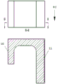
In the design of the laminated miniaturized digital subarray structure, the heat dissipation design of the frequency conversion plate which is far away from the cold plate and cannot be in direct contact with the cold plate is realized by adopting a U-shaped vapor chamber design mode, two ends of the U-shaped vapor chamber are respectively in contact with the cold plate and the frequency conversion plate, heat-conducting silicone grease is respectively coated on two end faces of the U-shaped vapor chamber, the contact thermal resistance is reduced, the heat dissipation efficiency is improved, and the efficient heat conduction of a heat dissipation device far away from the cold plate is realized.
Compared with the prior art, the invention has the following advantages:
the U-shaped soaking plate is used as a medium for heat conduction between the element far away from the cold plate and the cold plate, so that the heat conduction efficiency is greatly improved, and the heat dissipation efficiency of the miniaturized digital subarray is obviously improved.
1) The thermal resistance of the U-shaped soaking plate reaches 3.6 multiplied by 10-5m2K/W, the thermal resistance is low, the temperature uniformity reaches 4 ℃, and the heat conduction of devices far away from a cold plate can be effectively realized;
2) compared with the traditional forced air cooling heat dissipation mode, the application of the U-shaped soaking plate enables the heat dissipation capacity of the subarray system to be remarkably improved under the same condition.
Drawings
FIG. 1 is a schematic view of the structural assembly of the device of the present invention.
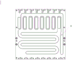
FIG. 2 is a schematic diagram of the layout of the water channels on the front side of the cold plate of the device of the present invention.
FIG. 3 is a schematic view of the reverse structure of the cold plate of the apparatus of the present invention.
FIG. 4 is a schematic view of the U-shaped soaking plate of the present invention.
In the figure: the device comprises a cold plate 1, a tile subarray 2, a U-shaped soaking plate 3, a power supply plate 4, a frequency conversion plate 5, a digital plate 6, a blind-plugging water plug 7, a flow channel cover plate 8, blind-plugging water plug mounting holes 9, a cold source 10 and a heat source 11.
Detailed Description
The invention provides a high-efficiency heat-dissipation miniaturized digital subarray which comprises a cold plate 1, a tile subarray 2, a U-shaped soaking plate 3, a power panel 4, a frequency conversion plate 5, a digital plate 6 and a blind-plugging water plug 7. Cold drawing 1 adopts the water route design that the microchannel cluster combined, and water course processing adopts electron beam welding process, and tile subarray 2, power strip 4 are installed on the cold drawing, and the heat source directly contacts with the cold drawing, and frequency conversion board 5 passes through U type soaking plate and cold drawing 1 contact, realizes heat-conduction. The digital subarray and an external water path are connected in a water path mode through blind-plugging water plugs 7.
In order to more clearly illustrate the embodiments of the present invention, the present invention is further described in detail below with reference to the drawings and examples of the specification.
The efficient heat dissipation miniaturized digital sub-array installation and use schematic diagram and the structure schematic diagram of each key part provided by the embodiment are shown in fig. 1 to 4. The water cooling plate comprises a cold plate 1 combined with series-parallel water channels, wherein the front surface of the cold plate 1 is fully distributed with a flow channel, the flow channel is realized by adopting an electron beam welding process, mounting holes for mounting other structural members are designed on the front surface and the back surface, and mounting holes for mounting blind-plugging water plugs are designed on the back surface. The tile subarray 2 is arranged on the front surface of the cold plate 1 and is in direct contact with the cold plate 1 for heat transfer. The power panel 4 is arranged on the back of the cold plate 1 and directly contacts with the heat dissipation boss on the cold plate 1 for heat transfer. The frequency conversion board is arranged on the inner side of the power supply board, and heat conduction is realized by the contact of the U-shaped soaking board 3 and the cold plate 1. The digit plate 6 is installed at the frequency conversion inboard, and 2 blind plug water plugs 7 are installed on two stabilizer blades of cold drawing 1, are regarded as respectively and advance back the liquid mouth.
The water channel layout of the cold plate 1 is as shown in fig. 2, the flow channel cover plate and the shell are welded and formed through electron beam welding, the water channel layout adopts a series-parallel connection combination mode, the heat exchange area of the flow passing through each tile subarray can be effectively increased, and the heat exchange efficiency is improved.
The variable frequency board 5 is arranged on the cold plate 1, the power supply board 4 is arranged between the variable frequency board 5 and the cold plate 1, and a heat source cannot be directly attached to the cold plate.
The heat dissipation performance indexes of the U-shaped soaking plate of the subarray system are shown in the table 1.
TABLE 1U-shaped soaking plate Performance index
| Serial number | Performance index | Measured value | Remarks for note |
| 1 | Temperature uniformity of U-shaped soaking |
4℃ | Measured value of |
| 2 | U-shaped soaking plate thermal resistance | 3.6×10⁻⁵m2·K/W | The thermal conductivity coefficient is 2000W/m.K |
| 3 | Surface temperature of |
65℃ | Forced air cooling is 73 DEG C |
Claims (2)
1. The utility model provides a high-efficient radiating miniaturized digital subarray which characterized in that: the intelligent water heater comprises a cold plate, a blind-mate plug, a tile subarray, a power panel, a frequency conversion plate, a digital plate and a U-shaped soaking plate; the blind-plugging water plug is arranged on the cold plate and is used for being connected with an external water path; the tile subarrays are arranged on one side of the cold plate and are tightly attached to the cold plate water channel; the power panel, the frequency conversion panel and the digital panel are respectively arranged on the other side of the cold plate.
2. A miniaturized digital sub-array with efficient heat dissipation as defined in claim 1, wherein: in the design of the laminated miniaturized digital subarray structure, the heat dissipation design of the frequency conversion plate which is far away from the cold plate and cannot be in direct contact with the cold plate adopts a U-shaped vapor chamber design mode, and the two ends of the U-shaped vapor chamber are respectively in contact with the cold plate and the frequency conversion plate, so that the efficient heat conduction of a heat dissipation device far away from the cold plate is realized.
Priority Applications (1)
| Application Number | Priority Date | Filing Date | Title |
|---|---|---|---|
| CN202010018318.8A CN111163620A (en) | 2020-01-08 | 2020-01-08 | High-efficient radiating miniaturized digital subarray |
Applications Claiming Priority (1)
| Application Number | Priority Date | Filing Date | Title |
|---|---|---|---|
| CN202010018318.8A CN111163620A (en) | 2020-01-08 | 2020-01-08 | High-efficient radiating miniaturized digital subarray |
Publications (1)
| Publication Number | Publication Date |
|---|---|
| CN111163620A true CN111163620A (en) | 2020-05-15 |
Family
ID=70562028
Family Applications (1)
| Application Number | Title | Priority Date | Filing Date |
|---|---|---|---|
| CN202010018318.8A Pending CN111163620A (en) | 2020-01-08 | 2020-01-08 | High-efficient radiating miniaturized digital subarray |
Country Status (1)
| Country | Link |
|---|---|
| CN (1) | CN111163620A (en) |
Citations (7)
| Publication number | Priority date | Publication date | Assignee | Title |
|---|---|---|---|---|
| CN201270640Y (en) * | 2008-08-29 | 2009-07-08 | 索士亚科技股份有限公司 | Overlapping type temperature equalizing board and heat radiation apparatus comprising the same |
| CN201293965Y (en) * | 2008-10-24 | 2009-08-19 | 索士亚科技股份有限公司 | Radiating module for notebook type computer |
| CN204906956U (en) * | 2015-09-14 | 2015-12-23 | 深圳市天健热技术有限公司 | Radiator |
| CN107561504A (en) * | 2017-07-27 | 2018-01-09 | 中国船舶重工集团公司第七二四研究所 | A kind of multichannel T/R inside modules three-dimensional blindmate structure implementation method |
| CN107579324A (en) * | 2017-07-27 | 2018-01-12 | 中国船舶重工集团公司第七二四研究所 | A kind of T/R components multichannel water power loads in mixture blindmate structure |
| CN110418555A (en) * | 2019-07-20 | 2019-11-05 | 中国船舶重工集团公司第七二四研究所 | The annular heat radiation apparatus of containing heat pipe inside |
| CN110645815A (en) * | 2019-09-29 | 2020-01-03 | 联想(北京)有限公司 | Vapor chamber and preparation method thereof |
-
2020
- 2020-01-08 CN CN202010018318.8A patent/CN111163620A/en active Pending
Patent Citations (7)
| Publication number | Priority date | Publication date | Assignee | Title |
|---|---|---|---|---|
| CN201270640Y (en) * | 2008-08-29 | 2009-07-08 | 索士亚科技股份有限公司 | Overlapping type temperature equalizing board and heat radiation apparatus comprising the same |
| CN201293965Y (en) * | 2008-10-24 | 2009-08-19 | 索士亚科技股份有限公司 | Radiating module for notebook type computer |
| CN204906956U (en) * | 2015-09-14 | 2015-12-23 | 深圳市天健热技术有限公司 | Radiator |
| CN107561504A (en) * | 2017-07-27 | 2018-01-09 | 中国船舶重工集团公司第七二四研究所 | A kind of multichannel T/R inside modules three-dimensional blindmate structure implementation method |
| CN107579324A (en) * | 2017-07-27 | 2018-01-12 | 中国船舶重工集团公司第七二四研究所 | A kind of T/R components multichannel water power loads in mixture blindmate structure |
| CN110418555A (en) * | 2019-07-20 | 2019-11-05 | 中国船舶重工集团公司第七二四研究所 | The annular heat radiation apparatus of containing heat pipe inside |
| CN110645815A (en) * | 2019-09-29 | 2020-01-03 | 联想(北京)有限公司 | Vapor chamber and preparation method thereof |
Similar Documents
| Publication | Publication Date | Title |
|---|---|---|
| CN107979962B (en) | Water-cooled circuit board heat abstractor | |
| CN108766946B (en) | Liquid cooling heat abstractor and motor controller | |
| CN113301762B (en) | Heat abstractor and phased array radar structure | |
| CN110475466B (en) | Air-cooled radiator and electrical equipment | |
| CN111163620A (en) | High-efficient radiating miniaturized digital subarray | |
| KR101373126B1 (en) | A Heat Exchanger using Thermoelectric Modules | |
| CN114679896A (en) | Tile type TR assembly heat pipe type air cooling radiator | |
| CN109974332B (en) | Water-cooling type semiconductor refrigerating device | |
| CN112285847A (en) | Multipath parallel optical module heat radiation structure | |
| CN220252530U (en) | Server radiator | |
| CN220755363U (en) | Module power supply heat dissipation assembly | |
| CN217086851U (en) | Tile type TR (transmitter-receiver) component heat pipe type air-cooled radiator | |
| CN217486756U (en) | Full-shielding digital high-power transmitting device | |
| CN219999879U (en) | TR module and TR combined module | |
| CN219457747U (en) | Battery module and battery box assembly | |
| CN209746117U (en) | Phased array radar T/R subassembly heat radiation structure | |
| CN218851204U (en) | Heat dissipation module and refrigerating device | |
| CN215188083U (en) | Chassis and robot | |
| CN212135345U (en) | Wireless network card for computer case | |
| CN220510169U (en) | Combined battery pack mounting connecting frame | |
| CN218784063U (en) | Heat dissipation heat sink for integrated circuit board | |
| CN219459637U (en) | Heat transfer device for successful radiation of annular array combination | |
| RU196690U1 (en) | Transceiver module of the active phased antenna array of the Ka-band with a two-stage cooling system | |
| CN216672160U (en) | Laser heat radiation structure | |
| CN219536653U (en) | Liquid cooling assembly, power module and power conversion equipment |
Legal Events
| Date | Code | Title | Description |
|---|---|---|---|
| PB01 | Publication | ||
| PB01 | Publication | ||
| SE01 | Entry into force of request for substantive examination | ||
| SE01 | Entry into force of request for substantive examination | ||
| WD01 | Invention patent application deemed withdrawn after publication |
Application publication date: 20200515 |
|
| WD01 | Invention patent application deemed withdrawn after publication |