Michelson optical fiber magnetic field sensing device and method
Technical Field
The invention belongs to the field of optical fiber sensing, and relates to a Michelson optical fiber magnetic field sensor.
Background
Magnetic field sensors are devices that convert various magnetic fields and the amount of their changes into readable signals. The traditional magnetic field sensor generally realizes measurement and calculation of a magnetic field through a Hall effect, a Faraday magneto-optical effect, a giant magnetic induction effect, a magnetic saturation effect and the like, but an active metal probe can disturb the distribution of the measured magnetic field, so that the measurement is not accurate, meanwhile, a cable for transmitting signals can generate noise, inconvenience is brought to the processing and analysis of the detected signals, and the defects of low anti-electromagnetic interference performance, low sensitivity, large loss and the like of the traditional magnetic field sensor are caused.
The optical fiber is widely applied to the sensing field due to the advantages of strong electromagnetic interference resistance, small loss, low cost and the like, and the Michelson interference type optical fiber magnetic field sensor is widely applied due to the advantages of simple structure, low power consumption and stable performance. In recent decades, with the development of micro-nano fiber preparation technology and magnetic material research, a novel micro-nano fiber magnetic field sensing technology based on a magnetofluid material becomes a hot point of research of people. The magnetic field sensing head is prepared by adopting a method of wrapping the micro-nano optical fiber by magnetic fluid. The micro-nano optical fiber can improve the sensitivity of a measuring magnetic field because the ambient evanescent field of the micro-nano optical fiber is very sensitive to the change of the refractive index of the external environment, but the micro-nano optical fiber preparation equipment is expensive and is easily influenced by external environment factors in the preparation process, the prepared micro-nano optical fiber has low mechanical strength and is easy to break, and the magnetic field sensing head is inconvenient to manufacture; the device for measuring the magnetic field by directly connecting the magnetic field sensing head with the spectrometer has poor stability, and the device is greatly influenced by external interference.
Aiming at the problems, the invention provides the Michelson optical fiber magnetic field sensor which is relatively low in cost, good in stability, simple and convenient in manufacturing process of a magnetic field sensing head and high in mechanical strength.
Disclosure of Invention
The Michelson optical fiber magnetic field sensor provided by the invention has the advantages of simple manufacturing process, lower system cost, stable performance and large developable space.
The following technical scheme is proposed for achieving the purpose:
a Michelson optical fiber magnetic field sensing device and a Michelson optical fiber magnetic field sensing method are characterized by comprising a broadband light source (1), an optical isolator (2), an optical fiber coupler (3), a first optical fiber mirror (4), a magnetic field sensing head (5), a second optical fiber mirror (6) and a spectrometer (7); the output of broadband light source (1) links to each other with the one end of optical isolator (2), the other end of optical isolator (2) links to each other with the A1 port of optical fiber coupler A end, the B1 port of optical fiber coupler B end is connected with first optical fiber mirror (3), the B2 port of optical fiber coupler B end is connected with the one end of magnetic field sensing head (5), the other end of magnetic field sensing head links to each other with second optical fiber mirror (6), the A2 port of optical fiber coupler A end links to each other with the optical input port of spectrum appearance (7).
The magnetic field sensing head adopts a sandwich structure of single-mode optical fiber-magnetofluid core optical fiber-single-mode optical fiber; when magnetic fluid filling is carried out, firstly, one end of a hollow quartz optical fiber which is not filled with magnetic fluid is connected with an injector by using an elastic rubber tube, then the other end of the hollow quartz optical fiber is inserted into magnetic fluid liquid, and the magnetic fluid liquid is pumped into the quartz hollow optical fiber by using the injector to complete filling, so that a magnetic fluid core optical fiber is obtained; and then, respectively plugging two ends of the magnetofluid core liquid core optical fiber by the single-mode optical fiber with the coating layer removed and the optical fiber end flattened, and sealing and reinforcing by using UV glue to finish the preparation of the magnetic field sensing head with the single-mode optical fiber-magnetofluid core liquid core optical fiber-single-mode optical fiber sandwich structure. The magnetic fluid in the magnetic fluid core-liquid core optical fiber does not show magnetism when not acted by a magnetic field, and the refractive index of the magnetic fluid changes along with the change of the magnetic field when acted by the magnetic field.
The optical fiber coupler, the first optical fiber mirror, the magnetic field sensing head and the second optical fiber mirror are connected to form a Michelson optical fiber interferometer, a port of the optical fiber coupler B1 is connected with the first optical fiber mirror to form a reference arm of the Michelson optical fiber interferometer, a port of the optical fiber coupler B2, the magnetic field sensing head and the second optical fiber mirror are connected to form a sensing arm of the Michelson optical fiber interferometer, and the first optical fiber mirror and the second optical fiber mirror are respectively used as reflecting mirrors of the reference arm and the sensing arm.
When the magnetic field environment of the magnetic field sensing head is changed, the free spectral range of the transmission spectrum of the Michelson fiber interferometer serving as a wide-spectrum light source cutting filter is also changed, and the size or the change of the magnetic field sensing head can be obtained through the change of the free spectral range of the transmission spectrum.
The working principle of the invention is as follows:
the broadband light source enters the Michelson optical fiber interferometer through the optical isolator and then is respectively transmitted into a reference arm and a sensing arm of the Michelson optical fiber interferometer, light of a light beam returning to the optical fiber coupler through the reference arm of the Michelson optical fiber interferometer is called as reference light, light returning to the optical fiber coupler through the sensing arm of the Michelson optical fiber interferometer is called as signal light, and the signal light and the reference light are subjected to double-beam interference in the optical fiber coupler. The magnetic field sensing head is in a sandwich structure of single-mode optical fiber-magnetic fluid core optical fiber-single-mode optical fiber. When the environment temperature is room temperature, when the environment of the magnetic field sensing head has a magnetic field or a magnetic field change, the refractive index n (H) of the magnetic fluid in the magnetic fluid core-liquid core optical fiber changes along with the change of the magnetic field according to the Langmuir formula, namely,
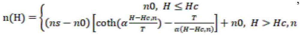
wherein n0 is the refractive index of the magnetofluid when the external magnetic field is smaller than a certain critical magnetic field intensity Hc, n, ns is the refractive index of the magnetofluid when the external magnetic field is saturated, T is the thermodynamic temperature, H is the external magnetic field intensity, α is an adjusting parameter.
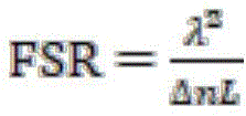
In the formula, λ is the wavelength of the input light source, Δ n is the change of the refractive index of the sensing region, that is, Δ n ═ n (h) -n0, and L is the length of the magnetofluid core optical fiber in the magnetic field sensing head. When a magnetic field or a magnetic field change exists in the environment where the magnetic field sensing head is positioned, the refractive index n (H) of the magnetic fluid core liquid core optical fiber is changed, so that the Michelson optical fiber interferometer is obtainedThe additional optical path difference between the reference arm and the sensing arm changes, namely delta is delta nL, so that the free spectral range FSR of the spectrum transmission response of the Michelson fiber interferometer changes, and the magnetic field size or the change of the environment where the magnetic field sensing head is located can be obtained according to the Laplace's formula through the change of the free spectral range FSR of the spectrum transmission response of the Michelson fiber interferometer.
The invention has the advantages that:
the magnetic field sensing head adopts a sandwich structure of single-mode optical fiber-magnetic fluid core optical fiber-single-mode optical fiber as the sensing head of the magnetic field sensor, has simple preparation process and high mechanical strength, does not need expensive special optical fiber processing equipment, has low sensing system cost and has wide development prospect.
Drawings
Fig. 1 is a schematic diagram of the michelson optical fiber magnetic field sensor principle.
The reference numerals in the figures are to be interpreted: the device comprises a broadband light source 1, an optical isolator 2, an optical fiber coupler 3, a first optical fiber mirror 4, a magnetic field sensing head 5, a second optical fiber mirror 6 and a spectrometer 7.
Detailed Description
The technical scheme of the invention is further explained by combining the attached drawings.
A Michelson optical fiber magnetic field sensing device and a Michelson optical fiber magnetic field sensing method are characterized by comprising a broadband light source (1), an optical isolator (2), an optical fiber coupler (3), a first optical fiber mirror (4), a magnetic field sensing head (5), a second optical fiber mirror (6) and a spectrometer (7); the output of broadband light source (1) links to each other with the one end of optical isolator (2), the other end of optical isolator (2) links to each other with the A1 port of optical fiber coupler A end, the B1 port of optical fiber coupler B end is connected with first optical fiber mirror (3), the B2 port of optical fiber coupler B end is connected with the one end of magnetic field sensing head (5), the other end of magnetic field sensing head links to each other with second optical fiber mirror (6), the A2 port of optical fiber coupler A end links to each other with the optical input port of spectrum appearance (7).
The magnetic field sensing head adopts a sandwich structure of single-mode optical fiber-magnetofluid core optical fiber-single-mode optical fiber; when magnetic fluid filling is carried out, firstly, one end of a hollow quartz optical fiber which is not filled with magnetic fluid is connected with an injector by using an elastic rubber tube, then the other end of the hollow quartz optical fiber is inserted into magnetic fluid liquid, and the magnetic fluid liquid is pumped into the quartz hollow optical fiber by using the injector to complete filling, so that a magnetic fluid core optical fiber is obtained; and then, respectively plugging two ends of the magnetofluid core liquid core optical fiber by the single-mode optical fiber with the coating layer removed and the optical fiber end flattened, and sealing and reinforcing by using UV glue to finish the preparation of the magnetic field sensing head with the single-mode optical fiber-magnetofluid core liquid core optical fiber-single-mode optical fiber sandwich structure. The magnetic fluid in the magnetic fluid core-liquid core optical fiber does not show magnetism when not acted by a magnetic field, and the refractive index of the magnetic fluid changes along with the change of the magnetic field when acted by the magnetic field.
The optical fiber coupler, the first optical fiber mirror, the magnetic field sensing head and the second optical fiber mirror are connected to form a Michelson optical fiber interferometer, a port of the optical fiber coupler B1 is connected with the first optical fiber mirror to form a reference arm of the Michelson optical fiber interferometer, a port of the optical fiber coupler B2, the magnetic field sensing head and the second optical fiber mirror are connected to form a sensing arm of the Michelson optical fiber interferometer, the reference arm is as long as the sensing arm, and the first optical fiber mirror and the second optical fiber mirror are respectively used as reflectors of the reference arm and the sensing arm.
When the magnetic field environment of the magnetic field sensing head is changed, the free spectral range of the transmission spectrum of the Michelson fiber interferometer serving as a wide-spectrum light source cutting filter is also changed, and the size or the change of the magnetic field sensing head can be obtained through the change of the free spectral range of the transmission spectrum.
The working mechanism of the invention is as follows:
the broadband light source enters the Michelson optical fiber interferometer through the optical isolator and then is respectively transmitted into a reference arm and a sensing arm of the Michelson optical fiber interferometer, light of a light beam returning to the optical fiber coupler through the reference arm of the Michelson optical fiber interferometer is called as reference light, light returning to the optical fiber coupler through the sensing arm of the Michelson optical fiber interferometer is called as signal light, and the signal light and the reference light are subjected to double-beam interference in the optical fiber coupler. The magnetic field sensing head is of a sandwich structure of single-mode optical fiber-magnetofluid core liquid core optical fiber-single-mode optical fiber, and when the ambient temperature is room temperature, a magnetic field exists in the environment where the magnetic field sensing head is located or the magnetic field is changedThe refractive index n (H) of the magnetic fluid in the magnetic fluid core-liquid core optical fiber changes along with the change of the received magnetic field according to the Langmuim formula
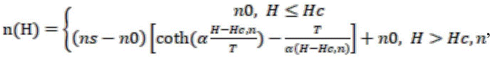
Wherein n0 is the refractive index of the magnetofluid when the external magnetic field is smaller than a certain critical magnetic field intensity Hc, n, ns is the refractive index of the magnetofluid when the external magnetic field is saturated, T is the thermodynamic temperature, H is the external magnetic field intensity, α is an adjusting parameter.
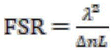
In the formula, λ is the wavelength of the input light source, Δ n is the change of the refractive index of the sensing region, that is, Δ n ═ n (h) -n0, and L is the length of the magnetofluid core optical fiber in the magnetic field sensing head. When a magnetic field or a magnetic field change exists in the environment where the magnetic field sensing head is located, the refractive index n (H) of the magnetic fluid core liquid core optical fiber is caused to change, so that the additional optical path difference between the reference arm and the sensing arm of the Michelson optical fiber interferometer is changed, namely delta is delta nL, the free spectral range FSR of the spectral transmission response of the Michelson optical fiber interferometer is changed, and the magnetic field size or the change of the environment where the magnetic field sensing head is located can be obtained according to the Langmy formula through the change of the free spectral range FSR of the spectral transmission response of the Michelson optical fiber interferometer.
The output spectral range of the broadband light source is C + L wave band, and the output power is 100 mW.
The optical isolator is used for ensuring unidirectional transmission of light output by the broadband light source and preventing light in the opposite direction from entering the broadband light source.
The optical fiber coupler is a 3dB optical fiber coupler.
The magnetofluid core-liquid core optical fiber is characterized in that magnetofluid filled in the magnetofluid core optical fiber is processed in a special proportion in order to ensure that the refractive index of magnetofluid in the fiber core is larger than that of the cladding of the magnetofluid core optical fiber.
The first optical fiber mirror and the second optical fiber mirror are both optical fiber mirrors with reflection functions.
The above detailed description of the working process of the present invention provides a person skilled in the art with the idea of the present invention that there may be variations in the specific implementation, and these variations should be considered as the protection scope of the present invention.

