CN111055272B - Machine claw with strong control performance - Google Patents
Machine claw with strong control performance Download PDFInfo
- Publication number
- CN111055272B CN111055272B CN201911301916.XA CN201911301916A CN111055272B CN 111055272 B CN111055272 B CN 111055272B CN 201911301916 A CN201911301916 A CN 201911301916A CN 111055272 B CN111055272 B CN 111055272B
- Authority
- CN
- China
- Prior art keywords
- plate
- fixed
- plates
- blocks
- grooves
- Prior art date
- Legal status (The legal status is an assumption and is not a legal conclusion. Google has not performed a legal analysis and makes no representation as to the accuracy of the status listed.)
- Active
Links
Images


Classifications
-
- B—PERFORMING OPERATIONS; TRANSPORTING
- B25—HAND TOOLS; PORTABLE POWER-DRIVEN TOOLS; MANIPULATORS
- B25J—MANIPULATORS; CHAMBERS PROVIDED WITH MANIPULATION DEVICES
- B25J9/00—Programme-controlled manipulators
- B25J9/10—Programme-controlled manipulators characterised by positioning means for manipulator elements
- B25J9/12—Programme-controlled manipulators characterised by positioning means for manipulator elements electric
-
- B—PERFORMING OPERATIONS; TRANSPORTING
- B25—HAND TOOLS; PORTABLE POWER-DRIVEN TOOLS; MANIPULATORS
- B25J—MANIPULATORS; CHAMBERS PROVIDED WITH MANIPULATION DEVICES
- B25J15/00—Gripping heads and other end effectors
-
- B—PERFORMING OPERATIONS; TRANSPORTING
- B25—HAND TOOLS; PORTABLE POWER-DRIVEN TOOLS; MANIPULATORS
- B25J—MANIPULATORS; CHAMBERS PROVIDED WITH MANIPULATION DEVICES
- B25J15/00—Gripping heads and other end effectors
- B25J15/08—Gripping heads and other end effectors having finger members
Abstract
The invention discloses a machine claw with strong handle control performance, which comprises a fixed plate, wherein the top of the fixed plate is fixedly connected with a fixed box, the top of the fixed box is fixedly provided with a servo motor, a threaded rod is longitudinally and rotatably arranged in the fixed box, the output shaft of the servo motor is fixedly arranged with the top end of the threaded rod, the threaded rod is in threaded connection with a fixed block, the fixed block is in sliding connection with the fixed box, the bottom of the fixed plate is provided with four grooves, the four grooves are mutually vertical, sliding blocks are respectively and slidably arranged in the four grooves, the four sliding blocks are respectively matched with the fixed block, lead screws are respectively and rotatably arranged in the four grooves, and. The invention relates to a machine claw with strong handle control performance, which can perform side extrusion fixing on an object by adopting four side extrusion plates to perform first fixed grabbing, and can perform bottom grabbing and mutual approaching further grabbing on the object by adopting four grabbing bottom plates to grab the object, so that the fixing effect and the handle control strength can be improved.
Description
Technical Field
The invention relates to the technical field of mechanical grippers, in particular to a mechanical gripper with strong handling and control performance.
Background
In industrial production or life, the object is picked and placed through common machine work, the object is picked and placed through the machine, the machine is used for picking the object by using the machine claw, the common machine claw is more in variety, two or more grabbing clamps are driven by power equipment such as a motor or hydraulic pressure to be close to each other to grab the object, and the purpose that the machine claw picks the object is achieved.
At present, the machine claw is simple in structure, can only fix and clamp an object through the mutual approaching of the grabbing clamp, is poor in fixed grabbing effect and weak in control performance, so that the machine claw with strong control performance is designed, and the problems are solved.
Disclosure of Invention
The invention aims to provide a machine claw with strong handle control performance so as to solve the problems in the background technology.
In order to achieve the purpose, the invention provides the following technical scheme: the utility model provides a machine claw that controllability is strong, which comprises a fixing plate and i, the fixed box of top fixedly connected with of fixed plate, the top fixed mounting of fixed box has servo motor, longitudinal rotation installs the threaded rod in the fixed box, servo motor's output shaft and the top fixed mounting of threaded rod, threaded connection has the fixed block on the threaded rod, fixed block and fixed box sliding connection, four recesses have been seted up to the bottom of fixed plate, four recess mutually perpendicular, equal slidable mounting has the sliding block in four recesses, four sliding blocks all cooperate with the fixed block, all rotate in four recesses and install the lead screw, sliding block and the lead screw threaded connection that corresponds, the bottom fixed mounting of sliding block has the side stripper plate, rotate on the side stripper plate and install the bottom plate of copying, fixed mounting helps the power plate on copying the bottom plate, help the plate and cooperate with.
Preferably, the inner walls of the tops of the four grooves are provided with movable holes, movable blocks are slidably mounted in the four movable holes, one ends of the four inclined rods are rotatably mounted on the outer sides of the fixed blocks, and the other ends of the four inclined rods are rotatably connected with the four movable blocks respectively.
Preferably, four cavities are formed in the fixed plate, rotating rods are installed in the four cavities in a longitudinal rotating mode, the screw rods are matched with the corresponding rotating rods, screw rods are connected to the rotating rods in a threaded mode, guide grooves are formed in the top of the boosting plate, guide blocks are slidably installed in the guide grooves, and the screw rods are rotatably connected with the corresponding guide blocks.
Preferably, one end of the screw rod extends into the corresponding cavity and is fixedly provided with a first bevel gear, a second bevel gear is fixedly arranged on the outer side of the rotating rod, and the first bevel gear is meshed with the second bevel gear.
Preferably, one side fixed mounting of side stripper plate has the stripper plate, and slidable mounting has the buffer board on the stripper plate, and the dashpot has been seted up to one side of buffer board, stripper plate and the dashpot sliding connection that corresponds, fixed mounting has a plurality of buffering springs between stripper plate and the dashpot that corresponds.
Preferably, the limiting grooves are formed in the inner walls of the two sides of the buffer groove, limiting blocks are slidably mounted in the limiting grooves, and the limiting blocks are fixedly connected with the corresponding extrusion plates.
Preferably, two limiting rods are fixedly installed between the inner wall of the top and the inner wall of the bottom of the fixing box, and the fixing block is connected with the two limiting rods in a sliding mode.
Preferably, four square holes are formed in the outer side of the fixed box, the four inclined rods are movably connected with the four square holes respectively, and two mounting blocks are fixedly mounted at the top of the fixed box.
Preferably, the specific using method is as follows:
(A1) before the electric fishing machine is used, the two mounting blocks are connected with the machine, the servo motor is connected with the controller and the power supply, when an object is grabbed, the four shoveling bottom plates and the four side extrusion plates are all positioned on the outer side of the object, the servo motor is started, the servo motor drives the threaded rod to rotate, the threaded rod drives the fixing block to move upwards, and the two limiting rods limit and guide the fixing block;
(A2) the fixed block moves upwards to drive the four moving blocks to approach each other through the four inclined rods, the four moving blocks respectively drive the four sliding blocks to approach each other, the four sliding blocks respectively drive the four lead screws to rotate, the four sliding blocks respectively drive the four side extrusion plates to approach each other, the four side extrusion plates are in contact extrusion with the object through the four buffer plates, and four directions of the object are simultaneously compressed and fixed;
(A3) the buffer plate is extruded when contacting with the object, and plays a role in buffering through the buffer spring, so that the impact of the buffer plate when just contacting with the object can be relieved, and the buffer protection effect is played;
(A4) when the screw rod rotates, the screw rod drives the corresponding rotating rod to rotate due to the arrangement of the first bevel gear and the second bevel gear, the rotating rod drives the corresponding screw rod to move downwards, the screw rod pushes the power-assisted plate to turn over through the guide block, the power-assisted plate drives the corresponding copying bottom plate to turn over to copy the bottom of the object, and the four copying bottom plates are close to each other and can simultaneously copy the bottom of the object to grab.
Compared with the prior art, the invention has the beneficial effects that:
1. the invention relates to a machine claw with strong handle control performance, which respectively drives four side extrusion plates to approach each other through four sliding blocks, the four side extrusion plates are in contact extrusion with an object through four buffer plates, and four directions of the object are simultaneously pressed and fixed;
2. the buffer plate is extruded when contacting with the object, and plays a role of buffering through the buffer spring, so that the impact of the buffer plate when just contacting with the object can be relieved, and the buffer protection effect is played;
3. the power plate drives the corresponding copying bottom plates to overturn to copy the bottom of the object, and meanwhile, the four copying bottom plates are close to each other, so that the object can be copied and grabbed at the same time.
4. The four side extrusion plates are adopted to extrude and fix the side of the object, so that the first fixed grabbing can be realized, the four grabbing bottom plates are adopted to grab the bottom of the object and approach each other for further grabbing, and the fixing effect and the handle control strength can be improved.
Drawings
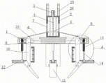
FIG. 1 is a schematic view of the main structure of the present invention;
FIG. 2 is a schematic top view of the present invention;
FIG. 3 is an enlarged view of the structure of FIG. 1 at A in accordance with the present invention;
FIG. 4 is a schematic perspective view of the connection structure of the fixing box and the mounting plate according to the present invention;
fig. 5 is a schematic view of a three-dimensional connection structure of the booster plate and the shoveling bottom plate of the invention.
In the figure: 1. a fixing plate; 2. a fixing box; 3. a servo motor; 4. a threaded rod; 5. a fixed block; 6. a diagonal bar; 7. a square hole; 8. a groove; 9. a slider; 10. a side extrusion plate; 11. a bottom board is copied; 12. a booster plate; 13. rotating the rod; 14. a screw rod; 15. a moving block; 16. a guide groove; 17. a guide block; 18. a first bevel gear; 19. a second bevel gear; 20. a pressing plate; 21. a buffer plate; 22. a buffer spring; 23. a lead screw; 24. a buffer tank; 25. mounting blocks; 26. a limiting rod; 27 cavity.
Detailed Description
The embodiment of the application solves the problems in the prior art by providing the machine claw with strong control performance. The following will clearly and completely describe the technical solutions in the embodiments of the present invention, and it is obvious that the described embodiments are only a part of the embodiments of the present invention, and not all embodiments. All other embodiments, which can be derived by a person skilled in the art from the embodiments given herein without making any creative effort, shall fall within the protection scope of the present invention.
Example one
Referring to fig. 1-5, the present embodiment provides a machine claw with strong handle control, which includes a fixing plate 1, a fixing box 2 is fixedly connected to the top of the fixing plate 1, the fixing box 2 supports a servo motor 3, the servo motor 3 is fixedly mounted on the top of the fixing box 2, the servo motor 3 provides power for grasping an object, a threaded rod 4 is longitudinally rotatably mounted in the fixing box 2, an output shaft of the servo motor 3 is fixedly mounted on the top end of the threaded rod 4, a fixing block 5 is threadedly connected to the threaded rod 4, the threaded rod 4 can drive the fixing block 5 to move, the fixing block 5 is slidably connected to the fixing box 2, four grooves 8 are formed in the bottom of the fixing plate 1, the four grooves 8 are perpendicular to each other, sliding blocks 9 are slidably mounted in the four grooves 8, the four sliding blocks 9 are all matched with the fixing block 5, and lead screws 23 are rotatably, the sliding block 9 is in threaded connection with the corresponding lead screw 23, the sliding block 9 can move to drive the corresponding lead screw 23 to rotate, a side extrusion plate 10 is fixedly installed at the bottom of the sliding block 9, the side extrusion plate 10 is used for fixing the side face of an object, a copying bottom plate 11 is rotatably installed on the side extrusion plate 10, the copying bottom plate 11 is used for grabbing the bottom of the object, a power assisting plate 12 is fixedly installed on the copying bottom plate 11, the power assisting plate 12 is used for driving the copying bottom plate 11 to turn over, and the power assisting plate 12 is matched with the corresponding lead screw 23.
In the embodiment, before use, two mounting blocks 25 are connected with a machine, a servo motor 3 is connected with a controller and a power supply, when an object is grabbed, four shoveling bottom plates 11 and four side extrusion plates 10 are positioned on the outer side of the object, the servo motor 3 is started, the servo motor 3 drives a threaded rod 4 to rotate, the threaded rod 4 drives a fixed block 5 to move upwards, the fixed block 5 moves upwards to drive four moving blocks 15 to approach each other through four inclined rods 6, the four moving blocks 15 respectively drive four sliding blocks 9 to approach each other, the four sliding blocks 9 respectively drive four lead screws 23 to rotate, the four side extrusion plates 10 are respectively driven to approach each other by the four sliding blocks 9, the four side extrusion plates 10 contact and extrude the object through four buffer plates 21, the four directions of the object are simultaneously pressed and fixed, the buffer plates 21 are extruded when contacting the object, and play a role in buffering through buffer springs 22, the impact of the buffer plate 21 when just contacting with an object can be relieved, because the first bevel gear 18 and the second bevel gear 19 are arranged, the lead screw 23 drives the corresponding rotating rod 13 to rotate, the rotating rod 13 drives the corresponding lead screw 14 to move downwards, the lead screw 14 pushes the power assisting plate 12 to turn over through the guide block 17, the power assisting plate 12 drives the corresponding bottom copying plate 11 to turn over to copy the bottom of the object, simultaneously, the four bottom copying plates 11 are close to each other and can simultaneously capture the copied bottom of the object, the invention adopts the four side extrusion plates 10 to extrude and fix the side of the object to play the first fixed capture, adopts the four bottom copying plates 11 to copy the bottom of the object and mutually close to each other to capture, after the object is moved to a proper position, the servo motor 3 is reversely started to enable the fixed block 5 to move downwards, so that the four side extrusion plates 10 are mutually far away from each other to loosen the object, and simultaneously, the four bottom copying plates 11 turn, the object is put down.
Example two
Referring to fig. 1-5, a further improvement is made on the basis of embodiment 1:
the inner walls of the tops of the four grooves 8 are respectively provided with a movable hole, a movable block 15 is slidably arranged in each of the four movable holes, one end of each of the four inclined rods 6 is rotatably arranged on the outer side of the fixed block 5, the other end of each of the four inclined rods 6 is rotatably connected with the corresponding movable block 15, the fixed block 5 can drive the corresponding movable block 15 to move through the inclined rods 6, four cavities 27 are formed in the fixed plate 1, rotating rods 13 are longitudinally and rotatably arranged in the four cavities 27, lead screws 23 are matched with the corresponding rotating rods 13, lead screws 14 are connected with the rotating rods 13 in a threaded manner, guide grooves 16 are formed in the tops of the power-assisted plates 12, guide blocks 17 are slidably arranged in the guide grooves 16, the lead screws 14 are rotatably connected with the corresponding guide blocks 17, the guide blocks 17 can slide in the guide grooves 16 to meet the movement of the power-assisted plates, one end of a lead screw 23 extends into a corresponding cavity 27 and is fixedly provided with a first bevel gear 18, a second bevel gear 19 is fixedly arranged on the outer side of the rotating rod 13, the first bevel gear 18 is meshed with the second bevel gear 19, the lead screw 23 drives the rotating rod 13 to rotate through the first bevel gear 18 and the second bevel gear 19, one side of the side extrusion plate 10 is fixedly provided with an extrusion plate 20, the extrusion plate 20 is provided with a buffer plate 21 in a sliding manner, one side of the buffer plate 21 is provided with a buffer groove 24, the extrusion plate 20 is in sliding connection with the corresponding buffer groove 24, a plurality of buffer springs 22 are fixedly arranged between the extrusion plate 20 and the corresponding buffer groove 24, the buffer springs 22 provide elasticity for the buffer plate 21, so that the impact force generated when the buffer plate 21 is contacted with an object can be relieved, the inner walls on the two sides of the buffer groove 24 are both provided with limit grooves, the limit blocks, stopper and spacing groove's cooperation can be spacing to buffer board 21, fixed mounting has two gag lever post 26 between the top inner wall of fixed box 2 and the bottom inner wall, fixed block 5 and two gag lever post 26 sliding connection, gag lever post 26 plays limiting displacement to fixed block 5, make fixed block 5 can only carry out the vertical migration, four quad slit 7 have been seted up in the outside of fixed box 2, four down tubes 6 respectively with four quad slit 7 swing joint, the top fixed mounting of fixed box 2 has two installation pieces 25, installation piece 25 is used for being connected with the machine erection.
In the description of the present invention, it should be noted that the terms "vertical", "upper", "lower", "horizontal", and the like indicate orientations or positional relationships based on those shown in the drawings, and are only for convenience of describing the present invention and simplifying the description, but do not indicate or imply that the referred device or element must have a specific orientation, be constructed and operated in a specific orientation, and thus, should not be construed as limiting the present invention. Furthermore, "first," "second," "third," and "fourth" are used for descriptive purposes only and are not to be construed as indicating or implying relative importance.
In the description of the present invention, it should be further noted that, unless otherwise specifically stated or limited, the terms "disposed," "mounted," "connected," and "connected" are to be construed broadly and may be, for example, fixedly connected, detachably connected, integrally connected, mechanically connected, electrically connected, directly connected, connected through an intermediate medium, or connected through the insides of two elements. The specific meanings of the above terms in the present invention can be understood by those skilled in the art according to specific situations.
Although embodiments of the present invention have been shown and described, it will be appreciated by those skilled in the art that changes, modifications, substitutions and alterations can be made in these embodiments without departing from the principles and spirit of the invention, the scope of which is defined in the appended claims and their equivalents.
Claims (7)
1. The utility model provides a strong machine claw of accuse nature, includes fixed plate (1), its characterized in that: the top of the fixed plate (1) is fixedly connected with a fixed box (2), the top of the fixed box (2) is fixedly provided with a servo motor (3), a threaded rod (4) is longitudinally and rotatably arranged in the fixed box (2), an output shaft of the servo motor (3) is fixedly arranged with the top end of the threaded rod (4), the threaded rod (4) is in threaded connection with a fixed block (5), the fixed block (5) is in sliding connection with the fixed box (2), the bottom of the fixed plate (1) is provided with four grooves (8), the four grooves (8) are mutually vertical, sliding blocks (9) are respectively and slidably arranged in the four grooves (8), the inner walls of the tops of the four grooves (8) are respectively provided with a movable hole, a movable block (15) is respectively and slidably arranged in the four movable holes, one end of four inclined rods (6) is rotatably arranged at the outer side of the fixed block (5), and the other ends of the, the fixed block (5) moves upwards to drive four moving blocks (15) to be close to each other through four inclined rods (6), the four moving blocks (15) respectively drive four sliding blocks (9) to be close to each other, the four sliding blocks (9) respectively drive four lead screws (23) to rotate, the four sliding blocks (9) respectively drive four side extrusion plates (10) to be close to each other to simultaneously compress and fix four directions of an object, the lead screws (23) are rotatably mounted in four grooves (8), the sliding blocks (9) are in threaded connection with the corresponding lead screws (23), the side extrusion plates (10) are fixedly mounted at the bottoms of the sliding blocks (9), a copying bottom plate (11) is rotatably mounted on the side extrusion plates (10), and a power assisting plate (12) is fixedly mounted on the copying bottom plate (11); four cavities (27) are formed in the fixed plate (1), rotating rods (13) are longitudinally and rotatably mounted in the four cavities (27), one end of each lead screw (23) extends into the corresponding cavity (27) and is fixedly mounted with a first bevel gear (18), a second bevel gear (19) is fixedly mounted on the outer side of each rotating rod (13), the first bevel gears (18) are meshed with the second bevel gears (19), the lead screws (23) drive the corresponding rotating rods (13) to rotate, the rotating rods (13) drive the corresponding lead screws (14) to move downwards, the lead screws (14) push the power assisting plates (12) to turn over through guide blocks (17), the power assisting plates (12) drive the corresponding power copying bottom plates (11) to turn over to copy the bottom of an object, meanwhile, the four power copying bottom plates 11 are close to each other to realize grabbing the bottom of the object, the lead screws (14) are in threaded connection with the rotating rods (13), guide grooves (16) are formed in the tops of the power assisting plates (, the guide groove (16) is internally provided with a guide block (17) in a sliding way, and the screw rod (14) is rotationally connected with the corresponding guide block (17).
2. A highly controlled machine jaw according to claim 1, characterized in that: one end of the screw rod (23) extends into the corresponding cavity (27) and is fixedly provided with a first bevel gear (18), the outer side of the rotating rod (13) is fixedly provided with a second bevel gear (19), and the first bevel gear (18) is meshed with the second bevel gear (19).
3. A highly controlled machine jaw according to claim 2, characterized in that: one side fixed mounting of side stripper plate (10) has stripper plate (20), and slidable mounting has buffer board (21) on stripper plate (20), and dashpot (24) have been seted up to one side of buffer board (21), stripper plate (20) and corresponding dashpot (24) sliding connection, fixed mounting has a plurality of buffering springs (22) between stripper plate (20) and corresponding dashpot (24).
4. A highly controlled machine jaw according to claim 3, characterized in that: the limiting grooves are formed in the inner walls of the two sides of the buffer groove (24), limiting blocks are arranged in the limiting grooves in a sliding mode, and the limiting blocks are fixedly connected with the corresponding extrusion plates (20).
5. A highly controlled machine jaw according to claim 1, characterized in that: two limiting rods (26) are fixedly mounted between the inner wall of the top and the inner wall of the bottom of the fixing box (2), and the fixing block (5) is connected with the two limiting rods (26) in a sliding mode.
6. A highly controlled machine jaw according to claim 1, characterized in that: four square holes (7) are formed in the outer side of the fixed box (2), the four inclined rods (6) are movably connected with the four square holes (7) respectively, and two mounting blocks (25) are fixedly mounted at the top of the fixed box (2).
7. The machine claw with strong control performance according to claim 4 is used by the following specific method:
(A1) before the electric fishing machine is used, the two mounting blocks (25) are connected with the machine, the servo motor (3) is connected with the controller and the power supply, when an object is grabbed, the four shoveling bottom plates (11) and the four side extrusion plates (10) are all positioned on the outer side of the object, the servo motor (3) is started, the servo motor (3) drives the threaded rod (4) to rotate, the threaded rod (4) drives the fixing block (5) to move upwards, and the two limiting rods (26) play a role in limiting and guiding the fixing block (5);
(A2) the fixed block (5) moves upwards to drive the four moving blocks (15) to approach each other through the four inclined rods (6), the four moving blocks (15) respectively drive the four sliding blocks (9) to approach each other, the four sliding blocks (9) respectively drive the four lead screws (23) to rotate, the four sliding blocks (9) respectively drive the four side extrusion plates (10) to approach each other, the four side extrusion plates (10) are in contact extrusion with an object through the four buffer plates (21), and four directions of the object are simultaneously compressed and fixed;
(A3) the buffer plate (21) is extruded when contacting with the object, and plays a role of buffering through the buffer spring (22), so that the impact of the buffer plate (21) when just contacting with the object can be relieved, and the buffer protection effect is played;
(A4) when the screw rod (23) rotates, the first bevel gear (18) and the second bevel gear (19) are arranged, so that the screw rod (23) drives the corresponding rotating rod (13) to rotate, the rotating rod (13) drives the corresponding screw rod (14) to move downwards, the screw rod (14) pushes the power assisting plate (12) to turn over through the guide block (17), the power assisting plate (12) drives the corresponding copying bottom plate (11) to turn over to copy the bottom of an object, and meanwhile, the four copying bottom plates (11) are close to each other and can simultaneously copy the bottom of the object to grab.
Priority Applications (1)
| Application Number | Priority Date | Filing Date | Title |
|---|---|---|---|
| CN201911301916.XA CN111055272B (en) | 2019-12-17 | 2019-12-17 | Machine claw with strong control performance |
Applications Claiming Priority (1)
| Application Number | Priority Date | Filing Date | Title |
|---|---|---|---|
| CN201911301916.XA CN111055272B (en) | 2019-12-17 | 2019-12-17 | Machine claw with strong control performance |
Publications (2)
| Publication Number | Publication Date |
|---|---|
| CN111055272A CN111055272A (en) | 2020-04-24 |
| CN111055272B true CN111055272B (en) | 2021-05-28 |
Family
ID=70301910
Family Applications (1)
| Application Number | Title | Priority Date | Filing Date |
|---|---|---|---|
| CN201911301916.XA Active CN111055272B (en) | 2019-12-17 | 2019-12-17 | Machine claw with strong control performance |
Country Status (1)
| Country | Link |
|---|---|
| CN (1) | CN111055272B (en) |
Families Citing this family (4)
| Publication number | Priority date | Publication date | Assignee | Title |
|---|---|---|---|---|
| CN109986499A (en) * | 2019-04-02 | 2019-07-09 | 安徽全柴锦天机械有限公司 | A kind of shaft block ring installation special tool |
| CN111871837A (en) * | 2020-08-04 | 2020-11-03 | 罗峰 | Numerical control cutter detects sieving mechanism |
| CN113024921A (en) * | 2021-02-07 | 2021-06-25 | 李春梅 | Preparation method of EPE environment-friendly packaging material |
| CN113084859A (en) * | 2021-03-15 | 2021-07-09 | 湖北天珊数控焊割设备有限责任公司 | Clamping head structure for industrial robot |
Citations (5)
| Publication number | Priority date | Publication date | Assignee | Title |
|---|---|---|---|---|
| JP2012081564A (en) * | 2010-10-13 | 2012-04-26 | Yaskawa Electric Corp | Hand, robot, and robot system |
| CN106584494A (en) * | 2016-12-22 | 2017-04-26 | 六安力达生产力促进中心有限公司 | Self-centering grabbing mechanism for manipulator |
| CN108015790A (en) * | 2017-11-16 | 2018-05-11 | 常州嘉业智能装备科技有限公司 | Pole plate grasping mechanism |
| CN108621185A (en) * | 2018-05-04 | 2018-10-09 | 旌德县瀚海星云智能化技术研发有限公司 | A kind of conveying robot with defencive function |
| CN110181545A (en) * | 2019-05-06 | 2019-08-30 | 江苏大学 | A kind of Multi Role Aircraft machinery claw |
-
2019
- 2019-12-17 CN CN201911301916.XA patent/CN111055272B/en active Active
Patent Citations (5)
| Publication number | Priority date | Publication date | Assignee | Title |
|---|---|---|---|---|
| JP2012081564A (en) * | 2010-10-13 | 2012-04-26 | Yaskawa Electric Corp | Hand, robot, and robot system |
| CN106584494A (en) * | 2016-12-22 | 2017-04-26 | 六安力达生产力促进中心有限公司 | Self-centering grabbing mechanism for manipulator |
| CN108015790A (en) * | 2017-11-16 | 2018-05-11 | 常州嘉业智能装备科技有限公司 | Pole plate grasping mechanism |
| CN108621185A (en) * | 2018-05-04 | 2018-10-09 | 旌德县瀚海星云智能化技术研发有限公司 | A kind of conveying robot with defencive function |
| CN110181545A (en) * | 2019-05-06 | 2019-08-30 | 江苏大学 | A kind of Multi Role Aircraft machinery claw |
Also Published As
| Publication number | Publication date |
|---|---|
| CN111055272A (en) | 2020-04-24 |
Similar Documents
| Publication | Publication Date | Title |
|---|---|---|
| CN111055272B (en) | Machine claw with strong control performance | |
| CN203449318U (en) | Stacking robot sucker gripper device | |
| CN105293060A (en) | Stable and efficient clamping moving picking device | |
| CN110127358A (en) | Mechanical paw and feeding robot | |
| CN111169981B (en) | Rotatory clamping jaw device of triaxial linkage and battery processing equipment | |
| CN110228706B (en) | Automatic adjusting industrial robot gripper | |
| CN113714953B (en) | Multi-process machining device for explosion-proof cabinet | |
| CN216465443U (en) | Be used for assembly type structure apparatus for producing for construction based on BIM technique | |
| CN215848284U (en) | Six-shaft grabbing mechanical arm with intelligent force control | |
| CN214421709U (en) | Distribution valve production equipment | |
| CN212124072U (en) | Automatic manipulator of injection molding machine rack | |
| CN210132157U (en) | Accumulator wall-through welding machine | |
| CN108288732B (en) | A kind of mechanical equipment automatically grabbing displacement for lithium battery | |
| CN208214928U (en) | A kind of stereo garage formula tool magazine | |
| CN220378214U (en) | Drill rod grabbing device of hydraulic drilling machine | |
| CN215853590U (en) | Flexible tongs of pile up neatly machine people centre gripping | |
| CN220739988U (en) | Positioner for welding battery replacement contact | |
| CN219404301U (en) | Rotary telescopic industrial manipulator | |
| CN219885129U (en) | Automatic hose stacking device with movable adjusting function | |
| CN216544568U (en) | Novel injection molding machine manipulator structure | |
| CN215395203U (en) | Automatic lifting device of manipulator platform | |
| CN220148553U (en) | Refractory brick power-assisted floating clamping device | |
| CN219751059U (en) | Cell module turning device | |
| CN219777743U (en) | Transmission mechanism for detecting quality of circuit board | |
| CN216229470U (en) | Device is got with robot clamp to intelligent manufacturing |
Legal Events
| Date | Code | Title | Description |
|---|---|---|---|
| PB01 | Publication | ||
| PB01 | Publication | ||
| SE01 | Entry into force of request for substantive examination | ||
| SE01 | Entry into force of request for substantive examination | ||
| GR01 | Patent grant | ||
| GR01 | Patent grant | ||
| TR01 | Transfer of patent right |
Effective date of registration: 20230801 Address after: Room 306, Building 13, Xinggong Science and Technology Park, No. 100 Luyun Road, High tech Development Zone, Changsha City, Hunan Province, 410000 Patentee after: Hunan Xiangyue Lingtong Automation Technology Co.,Ltd. Address before: 211100 two, B unit 300, Zhihui Road, Qilin science and Technology Innovation Park, Nanjing, Jiangsu. Patentee before: NANJING YUSHENG ROBOT TECHNOLOGY Co.,Ltd. |
|
| TR01 | Transfer of patent right |