CN111021749A - Simple hoisting mechanism for bare concrete exterior wall cladding and construction method thereof - Google Patents
Simple hoisting mechanism for bare concrete exterior wall cladding and construction method thereof Download PDFInfo
- Publication number
- CN111021749A CN111021749A CN202010039918.2A CN202010039918A CN111021749A CN 111021749 A CN111021749 A CN 111021749A CN 202010039918 A CN202010039918 A CN 202010039918A CN 111021749 A CN111021749 A CN 111021749A
- Authority
- CN
- China
- Prior art keywords
- rope
- lifting
- limiting
- hanging plate
- hoisting
- Prior art date
- Legal status (The legal status is an assumption and is not a legal conclusion. Google has not performed a legal analysis and makes no representation as to the accuracy of the status listed.)
- Pending
Links
Images
Classifications
-
- E—FIXED CONSTRUCTIONS
- E04—BUILDING
- E04G—SCAFFOLDING; FORMS; SHUTTERING; BUILDING IMPLEMENTS OR AIDS, OR THEIR USE; HANDLING BUILDING MATERIALS ON THE SITE; REPAIRING, BREAKING-UP OR OTHER WORK ON EXISTING BUILDINGS
- E04G21/00—Preparing, conveying, or working-up building materials or building elements in situ; Other devices or measures for constructional work
- E04G21/14—Conveying or assembling building elements
- E04G21/16—Tools or apparatus
- E04G21/167—Tools or apparatus specially adapted for working-up plates, panels or slab shaped building elements
-
- B—PERFORMING OPERATIONS; TRANSPORTING
- B66—HOISTING; LIFTING; HAULING
- B66C—CRANES; LOAD-ENGAGING ELEMENTS OR DEVICES FOR CRANES, CAPSTANS, WINCHES, OR TACKLES
- B66C1/00—Load-engaging elements or devices attached to lifting or lowering gear of cranes or adapted for connection therewith for transmitting lifting forces to articles or groups of articles
- B66C1/10—Load-engaging elements or devices attached to lifting or lowering gear of cranes or adapted for connection therewith for transmitting lifting forces to articles or groups of articles by mechanical means
- B66C1/22—Rigid members, e.g. L-shaped members, with parts engaging the under surface of the loads; Crane hooks
- B66C1/28—Duplicate, e.g. pivoted, members engaging the loads from two sides
-
- E—FIXED CONSTRUCTIONS
- E04—BUILDING
- E04G—SCAFFOLDING; FORMS; SHUTTERING; BUILDING IMPLEMENTS OR AIDS, OR THEIR USE; HANDLING BUILDING MATERIALS ON THE SITE; REPAIRING, BREAKING-UP OR OTHER WORK ON EXISTING BUILDINGS
- E04G21/00—Preparing, conveying, or working-up building materials or building elements in situ; Other devices or measures for constructional work
- E04G21/14—Conveying or assembling building elements
Landscapes
- Engineering & Computer Science (AREA)
- Architecture (AREA)
- Mechanical Engineering (AREA)
- Civil Engineering (AREA)
- Structural Engineering (AREA)
- Conveying And Assembling Of Building Elements In Situ (AREA)
Abstract
The invention discloses a simple hoisting mechanism for a bare concrete exterior wall cladding, which comprises a U-shaped ground anchor and a steel wire rope, wherein the U-shaped ground anchor is arranged on a floor slab, an outrigger is preset in the middle of the U-shaped ground anchor, the front end of the outrigger is provided with a pulley, the steel wire rope is assembled on the pulley, the lower part of the steel wire rope is provided with a lifting hook, the lifting hook is connected with a hoisting beam through an upper lifting lug, the lower part of the hoisting beam is provided with a hand-operated block, the lower lifting hook of the hand-operated block penetrates through a screw hoisting ring, and the screw hoisting ring is arranged on two sides of the. The invention has the beneficial effects that: the installation cost is reduced, the installation time is shortened, and the installation efficiency is greatly improved; has higher practical value and social and economic values; the reusability rate is high, the operation is easy to operate, and the operation is safe and reliable.
Description
Technical Field
The invention relates to construction of a bare concrete exterior wall cladding, in particular to a lifting mechanism suitable for the bare concrete exterior wall cladding.
Background
An assembled bare concrete exterior wall cladding is a novel building exterior wall decoration structure. At present, the building form is greatly popularized in the industry, and is characterized in that the traditional wet operations such as plastering and painting on site and the like are abandoned for the outer wall of the building. All the components installed on site are produced in factory workshops and then transported to the construction site for installation. The traditional installation mode is that a truck crane or a tower crane on a construction site is adopted for hoisting and installation. The defects of the truck crane are that the hoisting height is limited and influenced by the site, the driving route and the parking position of the truck crane are restricted to a certain extent, and the hoisting requirement is difficult to be completely met. When the tower crane in the construction site is adopted for hoisting, the occupied time of the tower crane is long, other operations needing hoisting in the construction site can be influenced, and the site construction efficiency is seriously reduced. And because there is driver operation sight blind area, the potential safety hazard when the link plate is installed has been increased. Particularly, in the operation step of lifting the bare concrete exterior wall cladding, the problem is solved by urgently needing a construction facility.
Disclosure of Invention
The invention aims to design a bare concrete exterior wall cladding lifting mechanism which is reasonable in structure and safe to use.
The invention has the technical scheme that the simple lifting mechanism for the bare concrete exterior wall cladding comprises a U-shaped ground anchor and a steel wire rope, and is characterized in that: be equipped with the U-shaped earth anchor on the floor, preset the outrigger in the middle of the U-shaped earth anchor, be equipped with the pulley at the front end of outrigger, be equipped with wire rope on the pulley, wire rope's lower part is equipped with the lifting hook, and the lifting hook is connected with the hoist and mount roof beam through last lug, is equipped with hand block in the lower part of hoist and mount roof beam, and hand block's lower lifting hook penetrates screw hoist and mount ring, and screw hoist and mount ring installs the both sides at clear water concrete link plate.
The two sides of the hoisting beam are provided with limiting U-shaped rings, the limiting U-shaped rings penetrate through limiting pull ropes, the limiting pull ropes are fixed to the lower portion of the floor slab and located on the two sides of the cantilever beam, the limiting pull ropes are symmetrically arranged, and the bottoms of the limiting pull ropes are fixed to the ground.
And the lower part of the hoisting beam is provided with a lower lifting lug for connecting a hand hoist.
And a steel wire rope clamping groove is arranged above the cantilever beam.
The outer end of the pulley is preset with an anti-skipping rope cross rod. The rope skipping prevention cross rod is a U-shaped rod, two ends of the rope skipping prevention cross rod are respectively fixed at the end part of the cantilever beam, and the rope skipping prevention cross rod is arranged around the outer side of the pulley; this prevents the wire rope from swinging out of the sheave.
And a rope skipping prevention cross rod can be arranged at the top of the cantilever beam and close to the pulley, and fixing pins are arranged at two ends of the rope skipping prevention cross rod and are wedged into the cantilever beam.
A construction method for lifting an exposed concrete exterior wall cladding is characterized by comprising the following steps:
1) firstly, a hoisting power device is in place, and a winch is generally adopted as a power output device; the winch is fixed firmly by finding a proper position, and one end of the steel wire rope is wound in the winch drum.
2) The installation outrigger is in place, the installation outrigger is placed right above the position where the exterior wall cladding is to be installed, the outrigger is made of I-shaped steel, the length is approximately within the range of 1.5m-2m, the top end of the outrigger extending out of the floor slab is provided with the upper part, the outrigger is suspended out of the floor slab by 50-70cm, and the other end of the outrigger is fixed with the floor slab by adopting a U-shaped ground anchor, a nut and the like to prevent overturning displacement.
3) The steel wire rope penetrates through the front section of the cantilever beam and extends into the pulley, and penetrates through the space between the cantilever beam pulley and the rope skipping prevention cross rod to directly reach the ground.
4) The limiting ropes are fixed on two sides of the cantilever beam, the distance between the two limiting ropes is the length of the hoisting beam, one end of each limiting rope is fixed on the floor slab, the other end of each limiting rope is fixed on the ground of the lowest floor, the protection between the limiting ropes and the floor slab is well done, and the phenomenon of rope fracture due to friction is prevented.
5) And (3) installing a hoisting beam, connecting the steel wire rope to a lifting lug on the hoisting beam by using a lock catch in the first step, penetrating a limiting rope through a limiting hole on the hoisting beam in the second step, fixing the hoisting beam in the range of the limiting rope, and respectively hanging hooks at one ends of two hand hoists at the lower lifting lug of the hoisting beam in the third step.
6) Promote the clear water concrete link plate, twist on clear water concrete link plate hole of hoist with screw hoist and mount ring, hang the couple of hand block other end on the hoist and mount ring, after firm, start the hoist engine and try to promote, slowly carry to leaving ground no longer than 30cm, treat that the link plate level is steady after, do not have to rock, the free from the abnormal shape after begin to continue to promote.
7) After the fair-faced concrete hanging plate is lifted to a floor to be installed, the winch stops working, the hanging plate is pulled to the position to be installed at the edge of the floor by a hook, two installation holes of the bottom foot of the fair-faced concrete hanging plate are aligned with the reserved installation holes of the floor, and then the L-shaped angle iron is used for fixing the hanging plate respectively; manually adjusting the height error of the hanging plate by using a manual hoist; and after the construction requirements are met, aligning the bare concrete hanging plate with the reserved mounting hole of the upper floor slab, and fixing the bare concrete hanging plate and the floor slab by using L-shaped angle iron respectively.
8) After the installation is completed, screw hoisting rings on two sides of the hanging plate are unscrewed, the winch is started, the hoisting beam is placed on the ground, and the next hanging plate is hoisted.
9) After the hanging plate is installed by the lifting mechanism, the lifting beam is placed on the ground, an upper lifting lug and a lifting hook are removed, a U-shaped limiting ring is removed from a limiting hole after loosening, a limiting rope is removed, the limiting rope is removed from a top floor and the ground after loosening, the limiting rope and the lifting rope are moved to the other hanging plate to be installed together, next round of installation is carried out again, a lifting steel wire rope is completely lifted and recovered to a winding drum of a winch, two ground anchor upper nuts at the rear part of the cantilever beam are removed, the U-shaped ground anchor is removed, the cantilever beam is recovered, the cantilever beam is transported to the position right above the other hanging plate to be installed by a trolley, and next round of cantilever beam installation in place is carried out.
The invention has the beneficial effects that: 1. compared with the traditional mode of using a crane and a tower crane for installation, the method has the advantages that the installation cost is reduced, the installation time is shortened, and the installation efficiency is greatly improved; 2. compared with the size of the outer wall cladding in the traditional mode, the size of the bare concrete outer wall cladding is larger, the weight is heavier, the traditional embedded part type installation mode can not meet the weight of the bare concrete outer wall cladding, and under the condition of pursuing the diversity of the outer wall decoration effect, the installation mechanism adopted by the invention completely meets the installation technology and the safety requirement of the large-size outer wall cladding, so that the mounting mechanism has higher practical value and social and economic values; 3. the hoisting mechanism is simple and convenient to mount and dismount; the repeated utilization rate is high, the operation is easy to operate, and the method is safe and reliable.
Drawings
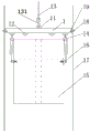
Fig. 1 is a schematic structural view of a hoisting beam part according to the present invention.
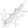
Fig. 2 is a schematic structural view of a mounting part of the cantilever beam on a floor slab according to the present invention.
Detailed Description
The embodiments are described in detail in connection with the above drawings,
in the case of the example 1, the following examples are given,
the utility model provides a simple and easy hoist mechanism of fair-faced concrete exterior wall cladding, it includes U-shaped earth anchor 22, wire rope 13, be equipped with U-shaped earth anchor on floor 21, predetermine in the middle of U-shaped earth anchor, and use U-shaped earth anchor to be fixed with outrigger 23, be equipped with pulley 25 at the front end of outrigger, be equipped with wire rope on the pulley, wire rope's lower part is equipped with lifting hook 131, the lifting hook is connected with hoist and mount roof beam 1 through last lug 11, be equipped with hand block 14 in the lower part of hoist and mount roof beam, hand block's lower lifting hook penetrates screw hoist and mount ring 16, screw hoist and mount ring installs the both sides at fair-faced concrete cladding 15.
In the case of the example 2, the following examples are given,
on the basis of embodiment 1, further be equipped with spacing U type ring 18 in the both sides of hoist and mount roof beam, spacing U type ring passes spacing stay cord 17, and spacing stay cord is fixed in the floor lower part, and is located the both sides of outrigger, and the symmetry sets up, and the bottom and the ground of spacing stay cord are fixed.
In this embodiment, the lower part of the hoisting beam is provided with a lower lifting lug 12 for connecting a hand hoist.
And a steel wire rope clamping groove 26 is arranged above the cantilever beam and used for clamping a steel wire rope.
An end rope skipping prevention cross bar 24 is preset at the outer end of the pulley. The rope skipping prevention cross rod is a U-shaped rod, two ends of the rope skipping prevention cross rod are respectively fixed at the end part of the cantilever beam, and the rope skipping prevention cross rod is arranged around the outer side of the pulley; this prevents the wire rope from swinging out of the sheave.
The rope skipping prevention cross rod 27 can be arranged at the top of the cantilever beam and close to the pulley, the rope skipping prevention cross rod is erected on the steel wire rope clamping groove in a straddling mode, fixing pins are arranged at two ends of the rope skipping prevention cross rod and are wedged into the cantilever beam, and the steel wire rope is further prevented from sliding out of the cantilever beam.
When the invention is used, the water-saving agent is added,
1) firstly, a hoisting power device is in place, and a winch is generally adopted as a power output device. The winch is fixed firmly by finding a proper position, and one end of the steel wire rope is wound in the winch drum.
2) Installing the cantilever beam in place. The mounting cantilever beam is arranged right above the position where the exterior wall cladding is to be mounted. The cantilever beam is made of I-shaped steel, the length of the cantilever beam is within the range of 1.5-2 m, the top end of the cantilever beam extending out of the floor slab is provided with an upper part, and the cantilever beam is cantilevered out of the floor slab by 50-70 cm. The other end of the cantilever beam is fixed with the floor slab by adopting a U-shaped ground anchor, a nut and the like to prevent overturning displacement.
3) The steel wire rope penetrates through the front section of the cantilever beam and extends into the pulley, and penetrates through the space between the cantilever beam pulley and the rope skipping prevention cross rod to directly reach the ground.
4) The limiting ropes are fixed on two sides of the cantilever beam, the distance between the two limiting ropes is the length of the hoisting beam, one end of each limiting rope is fixed on the floor slab, the other end of each limiting rope is fixed on the ground of the lowest floor, the protection between the limiting ropes and the floor slab is well done, and the phenomenon of rope fracture due to friction is prevented.
5) And (3) installing a hoisting beam, connecting the steel wire rope to a lifting lug on the hoisting beam by using a lock catch in the first step, penetrating a limiting rope through a limiting hole on the hoisting beam in the second step, fixing the hoisting beam in the range of the limiting rope, and respectively hanging hooks at one ends of two hand hoists at the lower lifting lug of the hoisting beam in the third step.
6) Promote the clear water concrete link plate, twist on clear water concrete link plate hole of hoist with screw hoist and mount ring, hang the couple of hand block other end on the hoist and mount ring, after firm, start the hoist engine and try to promote, slowly carry to leaving ground no longer than 30cm, treat that the link plate level is steady after, do not have to rock, the free from the abnormal shape after begin to continue to promote.
7) After the fair-faced concrete hanging plate is lifted to a floor to be installed, the winch stops working, the hanging plate is pulled to the position to be installed at the edge of the floor by a hook, two installation holes of the bottom foot of the fair-faced concrete hanging plate are aligned with the reserved installation holes of the floor, and then the L-shaped angle iron is used for fixing the hanging plate respectively; manually adjusting the height error of the hanging plate by using a manual hoist; and after the construction requirements are met, aligning the bare concrete hanging plate with the reserved mounting hole of the upper floor slab, and fixing the bare concrete hanging plate and the floor slab by using L-shaped angle iron respectively.
8) After the installation is completed, screw hoisting rings on two sides of the hanging plate are unscrewed, the winch is started, the hoisting beam is placed on the ground, and the next hanging plate is hoisted.
9) After the hanging plate is installed on the column through the lifting mechanism, the lifting beam is placed on the ground, the upper lifting lug and the lifting hook are removed, the limiting U-shaped ring is removed from the limiting hole after loosening, the limiting rope is removed from the top floor and the ground after loosening, and the limiting rope and the lifting hook are moved to the other column of hanging plates to be installed together to be installed again for next round of installation. And lifting the hoisting steel wire rope completely and recovering the hoisting steel wire rope to a winding drum of the hoisting machine, removing nuts on two ground anchors at the rear part of the cantilever beam, and removing the U-shaped ground anchor. And (4) withdrawing the cantilever beam, conveying the cantilever beam to the position right above the other row of hanging plates to be installed by using the trolley, and installing the cantilever beam of the next wheel in place.
The above examples are merely illustrative for clarity and are not intended to limit the embodiments. Other variations and modifications will be apparent to persons skilled in the art in light of the above description. It is not necessary or necessary to exhaustively enumerate all embodiments herein, and obvious variations or modifications can be made without departing from the scope of the invention.
Claims (7)
1. The utility model provides a simple and easy hoist mechanism of fair-faced concrete exterior wall cladding, it includes U-shaped earth anchor, wire rope, its characterized in that: be equipped with the U-shaped earth anchor on the floor, preset the outrigger in the middle of the U-shaped earth anchor, be equipped with the pulley at the front end of outrigger, be equipped with wire rope on the pulley, wire rope's lower part is equipped with the lifting hook, and the lifting hook is connected with the hoist and mount roof beam through last lug, is equipped with hand block in the lower part of hoist and mount roof beam, and hand block's lower lifting hook penetrates screw hoist and mount ring, and screw hoist and mount ring installs the both sides at clear water concrete link plate.
2. The simple lifting mechanism for the bare concrete exterior wall cladding as claimed in claim 1, is characterized in that: the two sides of the hoisting beam are provided with limiting U-shaped rings, the limiting U-shaped rings penetrate through limiting pull ropes, the limiting pull ropes are fixed to the lower portion of the floor slab and located on the two sides of the cantilever beam, the limiting pull ropes are symmetrically arranged, and the bottoms of the limiting pull ropes are fixed to the ground.
3. The bare concrete exterior wall cladding lifting mechanism of claim 1, wherein: and the lower part of the hoisting beam is provided with a lower lifting lug for connecting a hand hoist.
4. The simple lifting mechanism for the bare concrete exterior wall cladding as claimed in claim 1, is characterized in that: and a steel wire rope clamping groove is arranged above the cantilever beam.
5. The simple lifting mechanism for the bare concrete exterior wall cladding as claimed in claim 1, is characterized in that: an end rope skipping prevention cross rod is preset at the outer end of the pulley; the rope skipping prevention cross rod is a U-shaped rod, two ends of the rope skipping prevention cross rod are respectively fixed at the end part of the cantilever beam, and the rope skipping prevention cross rod is arranged around the outer side of the pulley.
6. The simple lifting mechanism for the bare concrete exterior wall cladding as claimed in claim 1, is characterized in that: the top of the cantilever beam is provided with an upper rope-skipping prevention cross rod at a position close to the pulley, two ends of the rope-skipping prevention cross rod are provided with fixing pins, and the fixing pins are wedged into the cantilever beam.
7. A construction method for lifting an exposed concrete exterior wall cladding is characterized in that:
1) firstly, a hoisting power device is in place, and a winch is generally adopted as a power output device; finding a proper position for the winch to be fixed firmly, and winding one end of the steel wire rope in the winch drum;
2) installing an outrigger in place, placing the installed outrigger right above a position to be installed on the exterior wall cladding, wherein the outrigger is made of I-shaped steel, the length of the outrigger is within the range of 1.5-2 m, the top end of the outrigger extending out of the floor slab is provided with an upper part, the outrigger is suspended out of the floor slab by 50-70cm, and the other end of the outrigger is fixed with the floor slab by adopting a U-shaped ground anchor, a nut and the like;
3) the steel wire rope penetrates through the front section of the cantilever beam and extends into the pulley, and penetrates through the space between the cantilever beam pulley and the rope skipping prevention cross rod to directly reach the ground;
4) fixing limiting ropes at two sides of the cantilever beam, wherein the distance between the two limiting ropes is the length of the hoisting beam, one end of each limiting rope is fixed on the floor slab, the other end of each limiting rope is arranged below the ground of the lowest floor and fixed on the ground, and the protection between each limiting rope and the floor slab is well done;
5) installing a hoisting beam, connecting the steel wire rope to an upper lifting lug of the hoisting beam by using a lock catch in the first step, penetrating a limiting rope through a limiting hole in the hoisting beam in the second step, fixing the hoisting beam in the range of the limiting rope, and respectively hanging hooks at one ends of two hand hoists at a lower lifting lug of the hoisting beam in the third step;
6) lifting the bare concrete hanging plate, screwing the bare concrete hanging plate on a lifting hole of the bare concrete hanging plate by using a screw lifting ring, hanging the hook at the other end of the hand-operated hoist on the lifting ring, starting a winch to try to lift after the bare concrete hanging plate is stable, slowly lifting the bare concrete hanging plate until the bare concrete hanging plate is not more than 30cm away from the ground, and starting to continue lifting after the hanging plate is level and stable and has no shake or abnormal shape;
7) after the fair-faced concrete hanging plate is lifted to a floor to be installed, the winch stops working, the hanging plate is pulled to the position to be installed at the edge of the floor by a hook, two installation holes of the bottom foot of the fair-faced concrete hanging plate are aligned with the reserved installation holes of the floor, and then the L-shaped angle iron is used for fixing the hanging plate respectively; manually adjusting the height error of the hanging plate by using a manual hoist; after the construction requirements are met, aligning the bare concrete hanging plate with the reserved mounting hole of the upper floor slab, and fixing the bare concrete hanging plate and the floor slab by using L-shaped angle iron respectively;
8) after the installation is finished, screwing off screw hoisting rings on two sides of the hanging plate, starting a winch, lowering the hoisting beam to the ground, and hoisting the next hanging plate;
9) after the hanging plate is installed by the lifting mechanism, the lifting beam is placed on the ground, an upper lifting lug and a lifting hook are removed, a U-shaped limiting ring is removed from a limiting hole after loosening, a limiting rope is removed, the limiting rope is removed from a top floor and the ground after loosening, the limiting rope and the lifting rope are moved to the other hanging plate to be installed together, next round of installation is carried out again, a lifting steel wire rope is completely lifted and recovered to a winding drum of a winch, two ground anchor upper nuts at the rear part of the cantilever beam are removed, the U-shaped ground anchor is removed, the cantilever beam is recovered, the cantilever beam is transported to the position right above the other hanging plate to be installed by a trolley, and next round of cantilever beam installation in place is carried out.
Priority Applications (1)
| Application Number | Priority Date | Filing Date | Title |
|---|---|---|---|
| CN202010039918.2A CN111021749A (en) | 2020-01-15 | 2020-01-15 | Simple hoisting mechanism for bare concrete exterior wall cladding and construction method thereof |
Applications Claiming Priority (1)
| Application Number | Priority Date | Filing Date | Title |
|---|---|---|---|
| CN202010039918.2A CN111021749A (en) | 2020-01-15 | 2020-01-15 | Simple hoisting mechanism for bare concrete exterior wall cladding and construction method thereof |
Publications (1)
| Publication Number | Publication Date |
|---|---|
| CN111021749A true CN111021749A (en) | 2020-04-17 |
Family
ID=70202854
Family Applications (1)
| Application Number | Title | Priority Date | Filing Date |
|---|---|---|---|
| CN202010039918.2A Pending CN111021749A (en) | 2020-01-15 | 2020-01-15 | Simple hoisting mechanism for bare concrete exterior wall cladding and construction method thereof |
Country Status (1)
| Country | Link |
|---|---|
| CN (1) | CN111021749A (en) |
Cited By (5)
| Publication number | Priority date | Publication date | Assignee | Title |
|---|---|---|---|---|
| CN112027935A (en) * | 2020-09-21 | 2020-12-04 | 杭州通达集团有限公司 | Hoisting construction method of PC (polycarbonate) wallboard used under window |
| CN114165061A (en) * | 2021-12-07 | 2022-03-11 | 北京城建集团有限责任公司 | Construction method of vertical transportation system |
| CN114314307A (en) * | 2022-03-09 | 2022-04-12 | 徐州奥星新型建材有限公司 | Concrete prefabricated part hoisting equipment with multipoint fixing function |
| CN114457692A (en) * | 2022-02-23 | 2022-05-10 | 中交一公局厦门工程有限公司 | Adjustable cast-in-place support platform is pour to reinforced concrete composite beam cantilever roof |
| CN115262984A (en) * | 2022-07-15 | 2022-11-01 | 上海二十冶建设有限公司 | Hoisting method for steel bar truss floor bearing plate inside building |
-
2020
- 2020-01-15 CN CN202010039918.2A patent/CN111021749A/en active Pending
Cited By (6)
| Publication number | Priority date | Publication date | Assignee | Title |
|---|---|---|---|---|
| CN112027935A (en) * | 2020-09-21 | 2020-12-04 | 杭州通达集团有限公司 | Hoisting construction method of PC (polycarbonate) wallboard used under window |
| CN112027935B (en) * | 2020-09-21 | 2023-02-03 | 杭州通达集团有限公司 | Hoisting construction method of PC (polycarbonate) wallboard used under window |
| CN114165061A (en) * | 2021-12-07 | 2022-03-11 | 北京城建集团有限责任公司 | Construction method of vertical transportation system |
| CN114457692A (en) * | 2022-02-23 | 2022-05-10 | 中交一公局厦门工程有限公司 | Adjustable cast-in-place support platform is pour to reinforced concrete composite beam cantilever roof |
| CN114314307A (en) * | 2022-03-09 | 2022-04-12 | 徐州奥星新型建材有限公司 | Concrete prefabricated part hoisting equipment with multipoint fixing function |
| CN115262984A (en) * | 2022-07-15 | 2022-11-01 | 上海二十冶建设有限公司 | Hoisting method for steel bar truss floor bearing plate inside building |
Similar Documents
| Publication | Publication Date | Title |
|---|---|---|
| CN111021749A (en) | Simple hoisting mechanism for bare concrete exterior wall cladding and construction method thereof | |
| CN107435438B (en) | Chimney rollover construction device | |
| CN113502924A (en) | Method for constructing steel beam in high-rise closed core cylinder | |
| CN109973112B (en) | Super-large-dip-angle narrow-space tunnel anchor cable saddle gantry system and installation method thereof | |
| CN112072560B (en) | Method for vertically laying super high-rise shaft cable in air through relay lifting | |
| CN105003082A (en) | Glass curtain wall mounting equipment and glass curtain mounting method | |
| CN102444271B (en) | Suspended scaffolding | |
| CN111764629A (en) | Method for mounting and dismounting inclined roof hanging basket without counterweight | |
| CN113137054A (en) | Method for setting inverted hoisting power equipment in attached lifting scaffold | |
| CN209873584U (en) | Hang basket template and demolish device | |
| CN216341336U (en) | Adjustable inverted frame structure of 750 x 750mm cross-section holding rod system | |
| CN205419580U (en) | A hoist and mount system for dismantling tower crane overlength pull rod | |
| CN211691536U (en) | Simple lifting mechanism for bare concrete exterior wall cladding | |
| CN215287701U (en) | Special lifting appliance for prefabricated wall | |
| CN107161879B (en) | Attached wall provision for disengagement and its method for dismounting on rear side of derrick crane | |
| JP2006299559A (en) | Self climbing scaffold and self climbing method by use of it | |
| CN204983692U (en) | Concrete panel's hoist device | |
| CN202988556U (en) | Special lifting appliance for angle-steel type frame body | |
| CN210885048U (en) | Large-scale equipment hoisting system | |
| CN101723240B (en) | Special fixture for hoisting rectangular section steel column and hoisting method by using same | |
| CN210029781U (en) | Anti-shaking device for hoisting | |
| KR101976724B1 (en) | Method for installing elevator guide rails without a machine room | |
| CN108729855B (en) | Drilling and mounting integrated anchor rod construction equipment and using method thereof | |
| CN218114849U (en) | Curtain wall material hoisting device | |
| CN218758804U (en) | Guide rail frame dismouting auxiliary device |
Legal Events
| Date | Code | Title | Description |
|---|---|---|---|
| PB01 | Publication | ||
| PB01 | Publication | ||
| SE01 | Entry into force of request for substantive examination | ||
| SE01 | Entry into force of request for substantive examination |