CN110997529B - Article sorting and sorting system - Google Patents
Article sorting and sorting system Download PDFInfo
- Publication number
- CN110997529B CN110997529B CN201880029863.8A CN201880029863A CN110997529B CN 110997529 B CN110997529 B CN 110997529B CN 201880029863 A CN201880029863 A CN 201880029863A CN 110997529 B CN110997529 B CN 110997529B
- Authority
- CN
- China
- Prior art keywords
- conveyor
- pop
- sorting
- article
- articles
- Prior art date
- Legal status (The legal status is an assumption and is not a legal conclusion. Google has not performed a legal analysis and makes no representation as to the accuracy of the status listed.)
- Active
Links
Images


Classifications
-
- B—PERFORMING OPERATIONS; TRANSPORTING
- B07—SEPARATING SOLIDS FROM SOLIDS; SORTING
- B07C—POSTAL SORTING; SORTING INDIVIDUAL ARTICLES, OR BULK MATERIAL FIT TO BE SORTED PIECE-MEAL, e.g. BY PICKING
- B07C5/00—Sorting according to a characteristic or feature of the articles or material being sorted, e.g. by control effected by devices which detect or measure such characteristic or feature; Sorting by manually actuated devices, e.g. switches
- B07C5/36—Sorting apparatus characterised by the means used for distribution
-
- B—PERFORMING OPERATIONS; TRANSPORTING
- B07—SEPARATING SOLIDS FROM SOLIDS; SORTING
- B07C—POSTAL SORTING; SORTING INDIVIDUAL ARTICLES, OR BULK MATERIAL FIT TO BE SORTED PIECE-MEAL, e.g. BY PICKING
- B07C3/00—Sorting according to destination
- B07C3/02—Apparatus characterised by the means used for distribution
-
- B—PERFORMING OPERATIONS; TRANSPORTING
- B07—SEPARATING SOLIDS FROM SOLIDS; SORTING
- B07C—POSTAL SORTING; SORTING INDIVIDUAL ARTICLES, OR BULK MATERIAL FIT TO BE SORTED PIECE-MEAL, e.g. BY PICKING
- B07C5/00—Sorting according to a characteristic or feature of the articles or material being sorted, e.g. by control effected by devices which detect or measure such characteristic or feature; Sorting by manually actuated devices, e.g. switches
- B07C5/04—Sorting according to size
- B07C5/10—Sorting according to size measured by light-responsive means
-
- B—PERFORMING OPERATIONS; TRANSPORTING
- B65—CONVEYING; PACKING; STORING; HANDLING THIN OR FILAMENTARY MATERIAL
- B65G—TRANSPORT OR STORAGE DEVICES, e.g. CONVEYORS FOR LOADING OR TIPPING, SHOP CONVEYOR SYSTEMS OR PNEUMATIC TUBE CONVEYORS
- B65G47/00—Article or material-handling devices associated with conveyors; Methods employing such devices
- B65G47/52—Devices for transferring articles or materials between conveyors i.e. discharging or feeding devices
- B65G47/53—Devices for transferring articles or materials between conveyors i.e. discharging or feeding devices between conveyors which cross one another
- B65G47/54—Devices for transferring articles or materials between conveyors i.e. discharging or feeding devices between conveyors which cross one another at least one of which is a roller-way
-
- B—PERFORMING OPERATIONS; TRANSPORTING
- B65—CONVEYING; PACKING; STORING; HANDLING THIN OR FILAMENTARY MATERIAL
- B65G—TRANSPORT OR STORAGE DEVICES, e.g. CONVEYORS FOR LOADING OR TIPPING, SHOP CONVEYOR SYSTEMS OR PNEUMATIC TUBE CONVEYORS
- B65G47/00—Article or material-handling devices associated with conveyors; Methods employing such devices
- B65G47/52—Devices for transferring articles or materials between conveyors i.e. discharging or feeding devices
- B65G47/68—Devices for transferring articles or materials between conveyors i.e. discharging or feeding devices adapted to receive articles arriving in one layer from one conveyor lane and to transfer them in individual layers to more than one conveyor lane or to one broader conveyor lane, or vice versa, e.g. combining the flows of articles conveyed by more than one conveyor
- B65G47/71—Devices for transferring articles or materials between conveyors i.e. discharging or feeding devices adapted to receive articles arriving in one layer from one conveyor lane and to transfer them in individual layers to more than one conveyor lane or to one broader conveyor lane, or vice versa, e.g. combining the flows of articles conveyed by more than one conveyor the articles being discharged or distributed to several distinct separate conveyors or to a broader conveyor lane
-
- B—PERFORMING OPERATIONS; TRANSPORTING
- B65—CONVEYING; PACKING; STORING; HANDLING THIN OR FILAMENTARY MATERIAL
- B65G—TRANSPORT OR STORAGE DEVICES, e.g. CONVEYORS FOR LOADING OR TIPPING, SHOP CONVEYOR SYSTEMS OR PNEUMATIC TUBE CONVEYORS
- B65G43/00—Control devices, e.g. for safety, warning or fault-correcting
- B65G43/08—Control devices operated by article or material being fed, conveyed or discharged
-
- B—PERFORMING OPERATIONS; TRANSPORTING
- B65—CONVEYING; PACKING; STORING; HANDLING THIN OR FILAMENTARY MATERIAL
- B65G—TRANSPORT OR STORAGE DEVICES, e.g. CONVEYORS FOR LOADING OR TIPPING, SHOP CONVEYOR SYSTEMS OR PNEUMATIC TUBE CONVEYORS
- B65G43/00—Control devices, e.g. for safety, warning or fault-correcting
- B65G43/10—Sequence control of conveyors operating in combination
Abstract
A sorting, unloading and article sorting system that automatically separates different package types includes a supply conveyor, a receiving conveyor, a sorting conveyor, a camera, and a photo-eye. The overhead camera detects the size of the object and whether it is cubic in nature and the type and size of the space it occupies. Tandem slide sorters with alternating conveyor rollers and pop-up belts transfer articles to or from a downstream conveyor. Vision-based systems may also be used to detect spaces between items and insert items into unoccupied spaces.
Description
Cross Reference to Related Applications
This application claims priority from us patent 10,427,884 granted on day 10/1 of 2019 from us application serial No. 15/588,230 filed on day 5/5 of 2017, which is incorporated herein by reference in its entirety.
Technical Field
The present invention relates to material handling and in particular to a method and apparatus for conveying packages, and to a mechanism for: the mechanism is used to sense the position and physical characteristics of the packages on a conveyance, such as a rail vehicle, aircraft, ship, or truck, to route the articles to the appropriate sorting system, and to control the rate of conveyance of the articles.
Background
Package delivery companies and airports utilize automated transport systems to match incoming packages with appropriate outgoing transport to the package destination.
For example, in the courier industry, shippers load truck trailers with mixed loads, including envelopes, packages, packs, bags, or discrete items of varying size, weight, and physical characteristics, including height, width, and length, as well as irregular dimensions. These items are divided into "small", "regular", and "non-regular/incompatible" groupings. Conventional methods of automating unloading devices have met with limited automation success. Robotic "gripper" technology is expensive. Sorting equipment must be very fast, yet provide gentle and accurate handling of packages of various sizes, shapes and sizes. Different sorting subsystems must be used to process different types of articles. Physical labor is still used to sort packages of unconventional shapes.
There is still a reliable need for separating items from a transport container, i.e. a trailer, depending on the type of package. Achieving this goal is particularly difficult in the case of large or heavy irregularly shaped packages. Belt and roller conveyor systems are commonly used in package sortation systems to move packages from an incoming loading dock to an outgoing transport. The initial sorting of packages travelling along the conveyor may be achieved by: packages are transferred from the conveyor based on their destination or based on their size, weight, or other characteristics.
Some conveyor systems include a main conveyor with a belt or a plurality of powered rollers or wheels that fit between wheels below the normal conveyor surface. Us patent No. 3,926,298 teaches a conveyor assembly in which a section of the drive roller can be lowered to drop a package onto the belt conveyor without interrupting the speed at which the articles move along the main path. However, the belt conveyor can only be shifted in one direction.
Us patent No. 5,547,084 teaches a baggage sorting system in which bags are fed onto a moving carriage comprising a plurality of conveyors. After loading, the carriage moves along the track until it is aligned with the output conveyor. The carriage conveyor then transfers the bag from the carriage to an appropriate output conveyor. This is not a high speed sorting system, as the bags must be stopped on the carriage and transported laterally, and then accelerated again after sorting.
Us patent 5,699,161 teaches a method and apparatus for measuring the dimensions of packages using a triangulation laser rangefinder.
Us patents 6,690,995 and 6,952,626 teach gravity center and size measuring devices and apparatus.
Conventional pop-up transfer conveyors require that as the articles pass the pop-up transfer conveyor, the incoming conveyor belt stops so that the conveyor's ejected belt can be raised and activated to transfer the articles onto a receiving or transfer conveyor, with the articles maintained in the proper orientation for conveyance on the receiving conveyor. A problem occurs when the incoming conveyor is not stopped with the articles above the pop-up conveyor because the longitudinal articles rotate sideways in the transfer program, which causes downstream orientation problems for the receiving conveyor.
In both the manual and automated cases, it is convenient to use a single expandable belt conveyor to transfer articles from within a trailer or storage facility for transport or container unloading. Different sorting subsystems process different types of articles. There is a need for a process to automatically separate different package types as the packages are unloaded from the trailer or transport, and for a diverter that can reliably divert irregularly shaped packages from the main conveyor path using a modular and easily maintained slide sorter mechanism, all while operating at high throughput speeds along the main path.
Disclosure of Invention
A slide sorter module located after the sorting lane discharge collection conveyor, the slide sorter module having a slide sorter central conveyor positioned to transfer the small articles to a first side conveyor positioned at a selected angle to and in flow communication with the central conveyor to convey the articles toward the receiving conveyor; and optionally, transferring articles of different sizes or shapes to a second side conveyor positioned at a selected angle to and in flow communication with the central conveyor to convey the articles toward an opposing receiving conveyor on a second side of the slide sorter module. The irregularities pass directly to a downstream receiving conveyor positioned in flow communication therewith.
The Vision-Based control System and the Slide Sorter Conveyor System are described in U.S. Pat. No. 10,358,298 entitled "Vision-Based Conveyor Package Flow Management System" entitled at 23.7.2019 and U.S. Pat. No. 9,771,222 entitled "Slide Sorter Point-Up converting Conveyor With Transfer Rate Based on Article Characteristics" entitled "patent Based on 26.9.2017, both of which are hereby incorporated by reference in their entirety.
The vision-based article sorting and separating system employs a vision-based system that includes a sorting channel that includes an unloading conveyor and at least one and preferably two or more overhead cameras and a low-positioned single-beam photo-eye. A camera is located in the air at each side of the conveyor and a low positioned single beam Photo Eye (PE) is located close to the camera location in the flow direction. The overhead camera detects the size of the object and whether it is cubic in nature and has a footprint that includes a flat bottom or an irregular bottom. Alternatively, a scale may be used in conjunction with the camera and PE to determine the destination of the item by weight.
A slide sorter module located after the sorting lane discharge collection conveyor, the slide sorter module having a slide sorter central conveyor positioned to transfer the small articles to a first side conveyor positioned at a selected angle to and in flow communication with the central conveyor to convey the articles toward the receiving conveyor; and optionally, transferring articles of different sizes or shapes to a second side conveyor positioned at a selected angle to and in flow communication with the central conveyor to convey the articles toward an opposing receiving conveyor on a second side of the slide sorter module. The irregularities pass directly to a downstream receiving conveyor positioned in flow communication therewith.
It is envisaged that line scan cameras conventionally have a single row of pixel sensors rather than a matrix of them. These lines are fed in series to a programmable controller or computer which links them to each other and makes images, for example, by connecting the camera output to the image capture card slot of an industrial computer. The image acquisition card is used to buffer the image and sometimes provides some processing before it is provided to the computer software for processing. Multiple rows of sensors can be used to make color images or the sensitivity can be increased by TDI (time delay and integration). Traditionally, maintaining consistent light over large 2D areas is quite difficult, and industrial applications often require a wide field of view. A line scan camera is used to provide uniform illumination across the "line" that the camera is currently viewing. This makes it possible to have a clear picture of an object passing through the camera at high speed and to be used as an industrial instrument for analyzing fast processes. It is contemplated that a 3D camera system utilizing one or more cameras or other pixel detection and/or digital imaging devices may also be used to detect the height of the package and determine bulk density.
A camera-based vision system identifies and maximizes belt area utilization of the discharge conveyor. A plurality of cameras are located at the flow entry points of the discharge feed conveyor and the receiving conveyor. A computer with a control algorithm identifies the area of each article, the footprint of the article and the rate at which each object passes and the area utilization of the unloaded tape. A video camera and computer based conveyor package management system monitors and controls the speed of the discharge conveyor based on the number and size of packages present on the discharge conveyor and the skid steer sorter. Information from receiving, collecting, separator and/or sorting conveyors in the package handling system may also be utilized, wherein camera data is used to measure the available area or space or volume on the conveyors to maintain a desired density of packages on a selected conveyor. The conveyor speed is controlled according to the occupancy on the collector or just before the sliding sorter conveyor, separator or receiver conveyor.
At least one camera, video camera or other pixel detection and/or digital imaging device is located at each individual input point, with control algorithms to identify incoming flow density in terms of both band utilization and throughput. These measures can be used to make changes to reduce the package input flow and if the flow is too dense, it may be necessary to stop the supply line. Similarly, no flow can be identified, prompting an increase in the speed of the input conveyor.
A camera positioned to view the splitter surface is similarly used to assess buffer capacity utilization, primarily based on area coverage identification. This feedback is used to dynamically adjust the behavior of the feed line. The use of webcams provides added benefits in terms of visibility of the system control room. Changes in parameters used to adjust the system can be evaluated in a more efficient manner. Clogging and other system problems are better identified.
A video camera and computer based conveyor package management system includes a video camera that monitors the number and size of packages present on an infeed conveyor, collector conveyor, separator conveyor and/or sortation conveyor in a package handling system, wherein the camera data is used to measure the available area or space or volume on the conveyors to maintain a desired package density on a selected conveyor. The conveyor speed is controlled according to the occupancy on the collector or just before the separator. The computer feeds information to the conveyor speed controller to introduce packages from one or more feed conveyors to the collecting conveyor, wherein the packages are detected by one or more cameras and the speed of the selected conveyor and/or the speed of the packages or articles is controlled to arrange the packages at an optimal spacing to maximize the density or volume of packages over a given conveyor area and the throughput of the system and correspondingly minimize the number of conveyors required by the system. When the computer determines that there is sufficient space on one of the conveyor belts (e.g., the collector belt), the computer tells the controller to add one or more packages by causing the feed belt to add one or more packages to the space or free area on the collector belt.
According to the present invention there is provided a video/camera based conveyor pack management system comprising, consisting of or consisting essentially of: a programmable logic controller or computer and a camera, video camera or other pixel detection and/or digital imaging device (collectively referred to as a video camera); a collector conveyor comprising different sections of the conveyor driven separately by separate motors with separate speed controls, selected ones of the sections of the collector conveyor having devices such as low friction conveying surfaces (e.g., deflection rollers) or high friction conveying surfaces capable of urging packages to selected sides of the collector conveyor; a plurality of infeed conveyors comprising different sections of the conveyors individually driven by separate motors having separate speed controllers; a first video camera monitoring the area of the collector conveyor leading up to the merge area of each feed conveyor with the collector conveyor; a second video camera monitoring the area of the feed conveyor leading up to the merge area of each feed conveyor with the collector conveyor; and a control program within the video computer capable of controlling the speed of the sections of the collector conveyor and the sections of the feed conveyor based on the calculated amount of free space on a given collector section as compared to the footprint of packages introduced on the feed conveyor, as calculated on a pixel-by-pixel basis providing digital information. The separator conveyor may be incorporated into the conveyor system and fed by the collector conveyor.
The present invention also utilizes a slide sorter that utilizes a pop-up conveyor or transfer mechanism to lift and transport selected articles, packages, packs, bags to another conveyor that is oriented in a different direction and is typically used in pallet handling, tray handling, etc. at a rate of up to 1500 pieces per hour that exceeds the rate at which trailers are typically unloaded. The pop-up conveyor is activated only if: the control system senses the movement of articles from the supply conveyor toward it by weight, footprint, flatness of the bottom of the footprint, surface area of the footprint or selected points determining length, width or height, digital camera pixels, photocells, infrared, laser or other electronic or radiation detection means. The pop-up conveyor is then raised above the surface level of the incoming conveyor as the article passes thereover to lift and support the article or a portion of the article on the conveyor device to transfer the article to a different conveyor or other article removal device. The pop-up conveyor typically remains inactive until the sensor senses that an article on the infeed conveyor is on the pop-up conveyor or in its immediate vicinity, whereupon the conveyor is activated to lift and engage the belt, rollers, chain drive, or a combination thereof, to contact the bottom surface of the article and push it at a selected angle and in a selected direction, typically 90 degrees away from the infeed conveyor.
The present invention includes a plurality of sensors arranged to detect an article of a selected size, weight, density or other physical characteristic and activate a pop-up conveyor for the article to separate and orient the article for further separation. In addition, the sensor can be set to allow an article (e.g., an envelope, a cube, or a package) having a selected characteristic to continue to travel through and over the pop-up conveyor to the outbound pass-through conveyor.
The slide sorter conveyor speed control system includes a first incoming flow conveyor positioned to carry articles in the direction of the longitudinal axis of the conveyor. A sliding sorter pop-up conveyor is positioned perpendicular or transverse to the longitudinal axis, the conveyor being transverse to the surface of the conveyor and flush with or slightly below the surface of the conveyor. It includes a transport mechanism that operates to move the pop-up conveyor between a home position in which the outfeed flow-through conveyor receives articles from the infeed throughfeed and conveys them in the direction of the longitudinal axis. A transfer or receiving conveyor is located on either or both sides of the flow conveyor and receives articles conveyed by the pop-up conveyor so that they move away from the longitudinal axis. One or more sensors (e.g., a multiplexed light curtain) are used to detect the full length of the object. A sensor, such as a photocell or photo eye or laser, fixed above the surface of the intake conveyor detects the portion of the irregular object that can be engaged by the pop-up conveyor. A computer control or PLC is provided to control the actuation of the pop-up conveyor in response to data transmitted from the multiplexed light curtain and photocell. Additionally, an array of height sensors may be used to detect the height of the article and slow the induct conveyor just prior to the taller article contacting the pop-up conveyor to prevent tipping of the top weight.
The vision-based article sorting and separation system may employ a vision-based system in conjunction with a sorting system.
The vision-based bulk package conveyor flow management system includes or consists of a supply conveyor and a receiving conveyor, each having independent drive means. A transition region is selected between the feeding conveyor and the receiving conveyor. At least one camera provides a selected transition region, a selected footprint, or a selected field of view of the selected transition region and the selected footprint. The discharge or feed conveyor, the receiver conveyor, or both are conveyed at a selected speed or time to achieve a desired conveyor area utilization on the downstream receiving conveyor according to the formula V2 = V1 x 2x (DO%)/(RCO% + FCO%), where V is speed (conveyor speed), DO is desired occupancy, RCO is receiving conveyor occupancy, and FCO is feeding conveyor occupancy. The feed conveyor has a selected occupancy defined area. The receiving conveyor has a selected occupancy defined area. The transition between the feeding conveyor and the receiving conveyor is adapted to merge a plurality of packages from one to the other. The selected transition section includes a desired occupancy percentage of the receiving conveyor after the packages from the feeding conveyor to the receiving conveyor are combined. The sensors provide input to a programmable logic control ("PLC") device, which is a digital computer used to automate industrial electromechanical processes. PLC provides a "hard" real-time system because output results must be generated in response to input conditions within a limited time otherwise unexpected operation will result. The computer calculates the desired footprint, conveyor speed and movement at the selected location based on signals received from the camera that identifies gaps between packages on the receiving conveyor that have sufficient space to insert additional packages from the feeding conveyor.
A sliding sorter conveyor speed control system includes a first upstream conveyor conveying a first group of articles of a selected size, shape, irregular base, marking, or other characteristic and a second group of articles of a selected different size, characteristic shape along a longitudinal axis of the first upstream conveyor. The second downstream conveyor conveys a first group of articles along a longitudinal axis of the second downstream conveyor. A pop-up or slide sorter conveyor is disposed between and in flow communication with the first upstream conveyor through the first group of articles. The pop-up conveyor diverts and conveys the second group of articles in a direction away from the second downstream conveyor. The pop-up conveyor includes a frame including a plurality of spaced parallel conveyor rollers disposed perpendicular to and at about the same elevation as the first upstream conveyor and the second downstream conveyor to receive and convey the first group of articles from the first upstream conveyor to the second downstream conveyor. A motor and drive are used to rotate the conveyor rollers. At least one pop-up belt is disposed between spaced conveyor rollers, the pop-up belt being spaced from and aligned parallel to the conveyor rollers, the conveyor rollers including a motor and drive means for rotating one of the pop-up belts. The pop-up belt remains in the inactive position a selected distance below the conveyor rollers during the passing of the first group of articles from the first upstream conveyor and through the conveyor rollers of the pop-up conveyor to the second downstream conveyor. The pop-up conveyor includes a cam device for raising the pop-up belt a selected distance above the conveyor rollers to convey and transfer a second group of articles from the second downstream conveyor. At least one multiplexed light curtain sensor that detects the full length of the first and second groups of items. The at least one photocell includes an emitter that projects at least a single beam of light at a selected distance above the surface of the first upstream conveyor. A receiver for receiving the at least one single beam detects a portion of an article in the first set of articles resting on the surface of the first upstream conveyor surface and detects a portion of an article in the second set of articles resting on the surface of the first upstream conveyor surface, which portions are engageable by the at least one pop-up belt. The variable speed control device is used for controlling the conveying speed of the first upstream conveyor. A computer control means is in electrical communication with the variable speed control means and the pop-up conveyor motor and the first upstream conveyor for controlling actuation of at least one pop-up belt of the pop-up conveyor in response to data transmitted from the multiplexed light curtain sensor and the photocell, thereby allowing the first group of articles to pass over the conveyor rollers and through the pop-up conveyor to the second downstream conveyor. The computer activates the cam device, which raises the at least one pop-up belt, which diverts the second group of articles away from the second downstream conveyor without stopping the first upstream conveyor and the second downstream conveyor. The computer receives input from the multiplexed light curtain sensor and controls the optimal speed of the first upstream conveyor based on the full length of the article and the portion of the article resting on the surface of the first upstream conveyor, thereby slowing the first upstream conveyor, and activates the pop-up conveyor, thereby raising the belt to engage the portion of the article to be transferred. The computer controls the duration of time the pop-up tape remains activated based on the full length of the item to be transferred. The computer controls the speed of the first upstream conveyor and slows the speed of the first upstream conveyor before the article engages the pop-up conveyor, as determined by the length of the article or the length of the first portion of the article that falls within the selected proximity of the pop-up conveyor.
A method of unloading, sorting and sorting articles from a bulk package conveyor stream using a vision management system and a pop-up slide sorter, comprising the steps of: identifying and sorting selected packages from an unload feed conveyor using a slide sorter pop-up conveyor comprises the steps of: a selected group of articles having a selected size, shape, irregular base, ID mark or other characteristic are conveyed along the longitudinal axis of the first upstream discharge feed conveyor by at least one photo eye device and/or at least one multiplexed light curtain sensor device that identifies and sorts articles to be passed to or diverted from the downstream conveyor. A pop-up or slide sorter conveyor is positioned between and in flow communication with the first upstream conveyor so that selected articles pass over the plurality of rollers and through the pop-up conveyor to the second downstream conveyor. The selected article is transferred by passing it through or using a pop-up conveyor having a plurality of tandem rollers and a driven belt raised above the surface of the rollers to contact the surface and transfer the selected article. A transition region may be selected between the feed conveyor and the receiving conveyor, each having an independent drive. The camera field of view of the selected transition region is determined so as to set the speed or motion of the feed conveyor, the receiving conveyor, or both the feed and receiving conveyors according to the formula V2 = V1 x 2x (DO%)/(RCO% + FCO%) to achieve a desired conveyor area utilization on the downstream receiving conveyor, where V is speed (conveyor speed), DO is desired occupancy, RCO is receiving conveyor occupancy, and FCO is feeding conveyor occupancy. The percentage of the supply conveyor occupancy defined area is determined, the percentage of the receiving conveyor occupancy defined area is determined, and a desired occupancy percentage of the receiving conveyor is selected for merging parcels from the supply conveyor to the receiving conveyor. A conveyor area is selected that includes a desired footprint at the selected location. Packages from the supply conveyor are supplied at a selected rate to the receiving conveyor occupancy defining area. The packages are conveyed towards the conveyor area at the desired footprint at the selected location. The packages at the conveyor area of the transition section are merged between the feeding conveyor and the receiving conveyor.
It is an object of the present invention to provide a conveyor pop-up slide sorter mechanism and speed sensing control system in which articles may be transferred without stopping the conveyor and without resting the articles prior to transferring them with the pop-up slide sorter, and without resting the articles on the ejectors prior to the ejectors being raised.
It is an object of the present invention to control the speed of the conveyor so that prior to pop-up transfer, the conveyor speed is reduced according to the length of the article or the length of the first portion falling within the close proximity of the conveying surface, which is close enough that the pop-up belt can be expected to engage the article and apply a lateral force to eject the article.
It is an object of the present invention to provide a sorting and article unloading collector conveyor for removing articles from a conveyance such as a trailer and utilizing a camera and computer system to determine the size, type, dimensions and irregularities of the articles for sorting the articles for processing.
It is an object of the present invention to provide a sensor to detect the area of an article resting on the conveyor to effect cooperative engagement with the pop-up conveyor.
It is an object of the present invention to provide a slide sorter speed control system with variable speed and/or multi-speed capabilities.
It is an object of the present invention to provide a slide sorter speed control system having at least three speeds, including the feed belt decelerating from 300 feet per minute to 100 or 200 feet per minute or remaining at 300 feet per minute before performing a transfer action.
It is an object of the present invention to provide different up point "encoder pulses" and down point "encoder pulses" for each speed according to the sensing eye.
It is an object of the present invention to incorporate a computer control system to measure and apply the fastest speed that can handle various items such as bumpers, chain saws, tables, tires, drums and 2x4 boards of varying length to gather a series of flat bottom speed criteria.
It is an object of the present invention to use a photo eye just above the belt surface to detect any object within about 3/8 inches above the belt.
It is an object of the present invention to provide a maximum safe speed calculated from the length of the object measured with the photo eye or the length of the first contact "pd" measured with the photo eye in a flat condition.
It is an object of the present invention wherein the speed length (speed length) is measured with the optical eye.
It is an object of the present invention to determine the hit point or the rise and fall points from a look-up table.
It is another object of the present invention to have variable rates for the incoming conveyor, outgoing conveyor, pop-up slide sorter conveyor, exit rollers, and receiver or diverter conveyors.
It is an object of the present invention to develop an ejector device which is raised periodically when the front portion of the object passes over the first lifting rail.
It is another object of the present invention to provide at least three speed adjustments, wherein at 300 feet per minute the hit point is 131 and the deceleration is 120, at 200 feet per minute the hit point is 134 and the deceleration is 125, and at 100 feet per minute the hit point is 139 and the deceleration is 126.
It is an object of the present invention to provide a pop-up tape having a speed of at least two meters per second (394 fpm) that is activated upon lifting.
It is an object of the present invention wherein the lift mechanism remains raised based on the article lift length measured with the second eye plus a length adder (length plus about 30 inches) using a feed tape encoder.
It is an object of the present invention to provide an acceleration rate as well as a deceleration rate and a speed of about 0.3G at deceleration.
It is an object of the present invention to provide a selected minimum clearance.
It is an object of the present invention to include an array of height sensors to detect high top heavy articles to control the conveyor to achieve maximum safe speed to prevent tipping over during conveyance by the slide sorter.
A vision-based sorting and separation system provides a method of managing bulk package conveyor flow with a vision management system, the method comprising or consisting of the steps of: a transition region is selected between the discharge feed conveyor and the receiving conveyor, each of which has an independent drive. The camera field of view of the selected transition region is selected. The speed or motion of the feed conveyor, the receiving conveyor, or both the feed and receiving conveyors is set according to the formula V2 = V1 x 2x (DO%)/(RCO% + FCO%) to achieve a desired conveyor area utilization on the downstream receiving conveyor, where V speed (conveyor speed), DO is the desired occupancy, RCO is the receiving conveyor occupancy, and FCO is the feeding conveyor occupancy. A percentage of the occupancy-limited area of the feed conveyor is determined. A percentage of the receiving conveyor occupancy defined area is determined. After merging packages from the feeding conveyor to the receiving conveyor, a percentage of a desired occupancy of the receiving conveyor is selected. A conveyor area is selected that includes a desired footprint at the selected location. Packages are fed from a feeding conveyor at a selected rate to a receiving conveyor occupancy defined area. The packages are conveyed towards a desired footprint of the conveyor area at the selected location. The packages are merged at the conveyor area of the transition between the feeding conveyor and the receiving conveyor.
A method of transferring selected packages from an unload feed conveyor using a slide sorter pop-up conveyor, comprising the steps of: a selected group of articles having a selected size, shape, irregular base, ID tag, or other characteristic is conveyed along a longitudinal axis of the first upstream discharge feed conveyor. A pop-up or slide sorter conveyor is disposed between and in flow communication with the first upstream conveyor for passing selected articles over the plurality of rollers and through the pop-up conveyor to the second downstream conveyor. The selected articles to be transferred are conveyed by means of a sliding sorter pop-up conveyor by driven belts of the pop-up conveyor that lift above the surface of the rollers to contact the surface of the conveyed articles in a direction away from the second downstream conveyor. The pop-up belts are spaced apart and aligned parallel to conveyor rollers that include motors and drives for rotating one of the pop-up belts. The pop-up belt remains in the inactive position a selected distance below the conveyor rollers during the passing of the first group of articles from the first upstream conveyor and through the conveyor rollers of the pop-up conveyor to the second downstream conveyor. The pop-up belt is lifted by the cam device a selected distance above the conveyor rollers to convey and divert a second group of articles away from the second downstream conveyor.
In certain applications, the photo eye and multiplexed light curtain sensors may be used with or in place of a camera to identify items to be sorted and transported to a particular location. Detecting the full length of selected ones of the first and second groups of items may be accomplished using at least one multiplexed light curtain sensor. At least one photocell is used with the emitter to detect a portion of an article resting on the surface of the first upstream conveyor surface that is engageable by the pop-up belt. The emitter projects at least a single beam at a selected distance above the surface of the conveyor toward the receiver. The conveying speed of the first upstream conveyor is controlled using a variable speed control device. A computer control in electrical communication with the variable speed control and the pop-up conveyor motor and the first upstream conveyor motor controls actuation of the pop-up belts of the pop-up conveyor in response to data transmitted from the multiplexed light curtain sensor and the photocell to allow the first group of articles to pass over the conveyor rollers and through the pop-up conveyor to the second downstream conveyor. Raising the pop-up belt diverts the selected article away from the second downstream conveyor without stopping the first upstream conveyor. The computer receives input from the multiplexed light curtain sensor, the camera, or both, and controls the optimal speed of the first upstream conveyor based on the full length of the article and the portion of the article resting on the surface of the first upstream conveyor, thereby slowing the first upstream conveyor, and activates the pop-up conveyor, thereby raising the belt to engage the portion of the article to be transferred. The computer controls the duration of time the pop-up tape remains activated based on the full length of the item to be transferred. The computer controls the speed of the first upstream conveyor and may slow the speed of the first upstream conveyor before the articles engage the pop-up conveyor. The speed of the feed conveyor, the pop-up conveyor, and the dwell time of the article on the pop-up conveyor are determined based on the length of the article or the length of the first portion of the article that falls within the selected proximity of the pop-up conveyor.
Other objects, features and advantages of the present invention will become apparent from the following detailed description taken in conjunction with the accompanying drawings which illustrate preferred embodiments of the invention.
Drawings
The present invention will be better understood by reference to the following description, taken in conjunction with the accompanying drawings, in which like reference numerals identify like parts throughout the several views, and in which:
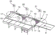
FIG. 1 is a perspective view of a vision-based article sorting and separating apparatus showing a truck, an extendable discharge collector feed conveyor extending from the floor of a trailer, a bracket supporting a pair of cameras, a photoelectric eye above the discharge conveyor in an occupancy-defined area, a percentage of a receiving conveyor occupancy-defined area, and a percentage in flow communication with a slide sorter conveyor in flow communication with a side conveyor and a downstream conveyor;
FIG. 2 is a perspective view of a section of a conveyor system as applied to a linear package separator, showing a feed conveyor and a receiving conveyor and a separator, wherein the roller and belt conveyors utilize independent motors to convey, arrange and separate packages, and the principle of conveyor area utilization can be controlled and package counting with a system having cameras positioned at the inflow entry points of selected conveyors to efficiently feed the separator or other sorting device;
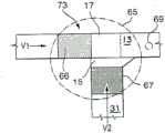
FIG. 3 is a top view of a video-based conveyor package management system for use with the sorting and sorting unloading system showing the camera field of view of the vision-based bulk parcel flow management system wherein the in-line conveyor speeds are set to achieve a desired conveyor area utilization on the downstream conveyor, including a percentage of camera field of view, a percentage of supply conveyors at a combined desired occupancy;
FIG. 4 illustrates camera fields of view of transition sections of a feed conveyor and a receiving conveyor, wherein each camera of the plurality of cameras provides a field of view to define a feed conveyor footprint, a receiving conveyor occupancy definition zone at a merge transition point of the upstream and downstream conveyors;
FIG. 5 is a top view illustrating the merging of a side-transferring feed conveyor with an intersecting collector conveyor, wherein the speed of the conveyors is set to achieve a desired conveyor area utilization on the downstream portion of the collector conveyor based on the camera field of view at the intersection based on a receiving conveyor occupancy defining area, a feed conveyor occupancy defining area, and a merged desired occupancy;
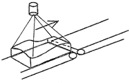
fig. 6 shows a prior art embodiment having an incoming flow-through conveyor having: a sliding sorter pop-up belt disposed at a 90 degree angle below the entry flow conveyor surface; and a diverter conveyor in flow communication with and adjacent to the slide sizer;
FIG. 7 is an enlarged view of a pop-up belt section of a prior art slide sorter showing a belt disposed between conveyor rollers that conveys articles flowing past the exit conveyor downstream of the slide sorter;
FIG. 8 shows a proximity switch (proxi switch) for providing position feedback to the PLC regarding the rollers of the slide sorter;
FIG. 9 shows a proximity sensor for detecting a home downward position on a cam for raising a pop-up belt between conveyor rollers of a slide sorter;
fig. 10 shows a flow-through conveyor having: a sliding sorter pop-up belt in flow communication with a pair of opposing 90 degree lead-away output lanes; and a sensor input comprising a multiplexed light curtain sensor that detects the length of the article, and a photocell (single beam) sensor that detects the portion of the article that can be engaged by the pop-up tape;
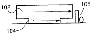
FIG. 11 is an example of a sensor input for an article having an irregular base, showing the height of the light sensor and photocell;
FIG. 12 is an example of sensor input for an occupancy space of an item having an irregular base;
FIG. 13 shows the footprint of an article on an incoming conveyor as measured by a second photo eye to determine the velocity length, thereby providing a value that can be translated by the encoder resolution to determine the maximum safe velocity approaching the slide sorter;
FIG. 14 shows a pair of footprints of an irregularly shaped article introduced onto a conveyor, the footprints measured by a second photo eye to determine a velocity length, thereby providing a value that can be converted by encoder resolution to determine a maximum safe velocity approaching a slide sorter;
FIG. 15 is a cross-sectional view into a flow-through conveyor showing the position of a first photo-eye and a second photo-eye;
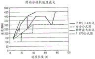
FIG. 16 shows a graph of the maximum flow rate of the speed of the slide sorter based on the speed versus the length of the speed;
FIG. 17 is an enlarged view of a multiplexed light curtain and photovoltaic cell disposed on an article, and a portion of the article may be engaged by a pop-up belt;
FIG. 18 is a flow-through conveyor with a tandem pop-up slide sorter having a parallel pull-off configuration including a multiplexed light curtain sensor and photocell sensor;
FIG. 19 is a perspective view of an in-and out-flow gate conveyor having a sliding sorter pop-up conveyor disposed therebetween, the pop-up conveyor being adjacent an exit roller extending parallel to the flow-through conveyor and perpendicular to the sliding sorter, wherein a diverter or receiver conveyor extends the length of the exit roller, showing a diverter conveyor roller disposed at a selected angle, wherein an outer roller is rearward of an inner roller adjacent the exit roller, thereby producing forward and lateral movement toward an outer wall and a leading edge of the diverter conveyor disposed below the level of the exit roller;
FIG. 20 is a downstream perspective view of the conveyor system shown in FIG. 19;
FIG. 21 is an upstream perspective view of the conveyor system shown in FIG. 19;
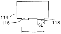
FIG. 22 is a cross-sectional end view of the pop-up transfer conveyor speed control assembly showing the entrance conveyor and the multiplexed light curtain sensor and photocell or photo eye, and a longitudinal article resting on the belt of the pop-up transfer conveyor in a raised position, partially rotating counterclockwise, supported by exit rollers, and extending over a portion of a diverter or receiver conveyor, wherein the pop-up belt is at a height above the entrance and exit flow-through conveyors (about 3/8 inches) and at the same height as the exit rollers (about 3/8 inches above the entrance and exit flow-through conveyors), and the receiving or diverter conveyor rollers are positioned about 1/8 inches below the height of the exit rollers and the flow-through conveyor, wherein the receiving diverter conveyor is tilted upward at a selected angle of 1-35 relative to the flow-through conveyor, contacting the articles with the receiving conveyor after extending over about 25% of the width of the receiving conveyor;
FIG. 23 is a perspective view of the pop-up transfer conveyor speed control assembly showing a longitudinal article resting on the in-feed conveyor and passing through a multiplexed light curtain sensor and photocell or photo eye, the pop-up transfer conveyor in a downward rest position, exit rollers and diverter or receiver conveyor, and the out-flow conveyor;
FIG. 24 is a side view of the pop-up transfer conveyor speed control assembly showing a longitudinal article resting on the in-feed conveyor and passing through a multiplexed light curtain sensor and photocell or photo eye, the pop-up transfer conveyor in a downward rest position, exit rollers and diverter or receiver conveyor, and the out-flow conveyor;
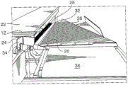
FIG. 25 is a perspective view of the pop-up conveyor speed control assembly showing a tall cylindrical article, such as a drum or bucket, with one end resting on the entry conveyor and passing through a multiplexed light curtain sensor and array of photocells or light eyes and sensors positioned to measure the height of the article and its length, wherein the pop-up conveyor is shown in a downward resting position below the surface of the flow-through conveyor and showing exit rollers and a diverter or receiver conveyor;
FIG. 26 is a side view of the pop-up conveyor speed control assembly showing a drum resting on an incoming flow-through conveyor and passing a multiplexed light curtain sensor and photocell and height sensor array, with the pop-up conveyor in a downward resting position adjacent to an exit roller and diverter or receiver conveyor;
FIG. 27 is a cross-sectional end view of the pop-up transfer conveyor speed control assembly showing a drum resting on an incoming flow-through conveyor and passing through a multiplexed light curtain sensor and light eye and height sensor array, wherein the pop-up transfer conveyor is in a downward resting position adjacent to exit rollers and a receiver conveyor shown at an oblique angle of 1 to 35;
FIG. 28 is a perspective view of the pop-up transfer conveyor speed control assembly showing the entry conveyor and the multiplexed light curtain sensor, photocell, and height sensor array with the drum supported on a raised belt of the pop-up transfer conveyor above the entry and exit flowthrough conveyor surfaces that in an upwardly raised position supports the drum above the entry flow conveyor surface and flush with the exit roller and a portion (approximately 25% of the width) of the adjacent receiver conveyor roller;
FIG. 29 is a side view of the pop-up transfer conveyor speed control assembly showing the entry conveyor and the multiplexed light curtain sensor, photocell and height sensor array, and the drums supported on the belt of the pop-up transfer conveyor in a raised position;
FIG. 30 is a cross-sectional end view of the pop-up conveyor speed control assembly showing the entrance conveyor and the multiplexed light curtain sensor and photocell or photo eye, as well as the drum resting on the belt of the pop-up conveyor, the exit conveyor, and a portion of the receiver conveyor rollers all in flush horizontal alignment with one another;
fig. 31 is a perspective view of a section of a conveyor system showing a feed conveyor and a receiving conveyor, wherein the conveyors employ the principle of conveyor area utilization and package counting with a system that: the system has a camera located at the stream entry point of a selected conveyor that is controlled to feed the downstream receiving conveyor efficiently, and the velocity V2 of incoming material on the feeding conveyor occupancy defined area (FCO%) is proportional to the velocity V1 of outgoing material in the designated area defining the desired occupancy (DO%) of the downstream receiving conveyor after delivery. A ratio V2/V1 is proportional to the ratio of the area desired to be covered by the item to the percentage of the incoming area covered by the item, where the ratio = V2/V1 = (DO%)/(FCO%); and
fig. 32 is a perspective view illustrating the use of a laser height sensor to be used to convert the volume of a bulk package flow from an incoming volume to a selected package volume over an area of the same size.
Detailed Description
The terminology used herein is for the purpose of describing particular example embodiments only and is not intended to be limiting. As used herein, the singular forms "a", "an" and "the" may be intended to include the plural forms as well, unless the context clearly indicates otherwise. The terms "comprises," "comprising," "including," and "having" are inclusive and therefore specify the presence of stated features, integers, steps, operations, elements, and/or components, but do not preclude the presence or addition of one or more other features, integers, steps, operations, elements, components, and/or groups thereof. The method steps, processes, and operations described herein are not to be construed as necessarily requiring their performance in the particular order discussed or illustrated, unless specifically identified as an order of performance. It should also be understood that additional or alternative steps may be employed.
When an element or layer is referred to as being "on," "engaged to," "connected to," or "coupled to" another element or layer, it can be directly on, engaged, connected or coupled to the other element or layer, or intervening elements or layers may also be present. In contrast, when an element is referred to as being "directly on," "directly engaged to," "directly connected to" or "directly coupled to" another element or layer, there may be no intervening elements or layers present. Other terms used to describe the relationship between elements (e.g., "between" and "directly between", "adjacent" and "directly adjacent", etc.) should be interpreted in a similar manner. As used herein, the term "and/or" includes any and all combinations of one or more of the associated listed items.
Although the terms "first," "second," "third," etc. may be used herein to describe various elements, components, regions, layers and/or sections, these elements, components, regions, layers and/or sections should not be limited by these terms. These terms may be only used to distinguish one element, component, region, layer or section from another region, layer or section. Terms such as "first," "second," and other numerical terms when used herein do not imply a sequence or order unless clearly indicated by the context. Thus, a first element, component, region, layer or section discussed below could be termed a second element, component, region, layer or section without departing from the teachings of the example embodiments.
Spatially relative terms, such as "inner," "outer," "below," "lower," "upper," and the like, may be used herein for ease of description to describe one element or feature's relationship to another element or feature or features as illustrated. Spatially relative terms may be intended to encompass different orientations of the device in use or operation in addition to the orientation depicted in the figures. For example, if the device in the figures is turned over, elements described as "below" or "beneath" other elements or features would then be oriented "above" the other elements or features. Thus, the exemplary term "below" can encompass both an orientation of above and below. The device may be otherwise oriented (rotated 90 degrees or at other orientations) and the spatially relative descriptors used herein interpreted accordingly.
As used herein, the term "about" is reasonably understood by one skilled in the art to mean slightly above or slightly below the stated value, to within ± 10%.
The present invention now will be described more fully hereinafter with reference to the accompanying drawings, in which preferred embodiments of the invention are shown. This invention may, however, be embodied in many different forms and should not be construed as limited to the embodiments set forth herein; rather, these embodiments are provided so that this disclosure will be thorough and complete, and will fully convey the scope of the invention to those skilled in the art. Like reference numerals refer to like elements throughout.
As shown in fig. 1-32, a vision-based article sorting and sorting conveyor apparatus utilizing a computer camera vision system and a sliding sorter pop-up transfer conveyor and speed control system 10 provides a means for selecting and sorting articles unloaded from a conveyance, such as a truck, for sorting in the conveyor system.
As shown in fig. 1, the vision-based article sorting and separating apparatus includes a sorting system portion to distinguish regular packages 8 from irregular packages 9 and small packages, the sorting system portion including a transport vehicle such as a trailer 1, an extendable discharge-feed conveyor 22 extending from the floor 3 of the trailer 1, a pair of overhead cameras 5,6, and at least one photo- eye sensor 102, 104, 106 above the discharge-feed conveyor 22 within a sort-defining area 170. The cameras are located in the air at each side of the discharge feed conveyor 22 and a low positioned single beam Photo Eye (PE) is located close to the camera location in the flow direction. The overhead camera detects the size of the object and whether it is cubic in nature and has a footprint that includes a flat bottom or an irregular bottom. Alternatively, the scale 7 may be used in conjunction with a camera and photo-eye to determine the destination of the item by weight.
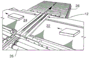
Located after the sorting lane unload collection conveyor is an article removal device such as a pop-up bi-directional slide sorter conveyor 12 in flow communication with an unload feed conveyor 22 and a downstream conveyor 24 and including at least one and preferably two side conveyors 26, the side conveyors 26 being comprised of powered off skewed roller conveyors 28, the conveyors 28 being in flow communication with the slide sorter conveyor 12 within a separation conveyor occupancy defined area 171. The sliding sorter central conveyor pop-up element 14 may be positioned to transfer small articles 11 to the first side conveyor 26 and positioned at a selected angle to the sliding sorter conveyor 12 and in flow communication with the sliding sorter conveyor 12 to convey the articles toward the receiving conveyor 24 and, optionally, to transfer different sized regular parcels 8 or different shaped articles to the second side conveyor positioned at a selected angle to the central sliding sorter conveyor 12 and in flow communication with the central sliding sorter conveyor 12 to convey the articles toward the opposing receiving conveyor on the second side of the sliding sorter module. The irregular packages 9 pass directly to a downstream receiving conveyor 24 positioned in flow communication therewith. Optionally, exit rollers 25 may be utilized between the slide sorter conveyor and the side conveyor 26 to assist in the rapid removal of parcels from the slide sorter conveyor 12.
The sorting and article sorting system includes or consists of an unload collector supply conveyor having an independent drive motor in flow communication with a transport loaded with articles. A selected transition region on the unload collector feed conveyor. At least one camera having a field of view of the transition region. The controller device maintains the unload collector feed conveyor speed according to the formula V2 = V1 x 2x (DO%)/(RCO% + FCO%) to achieve a desired conveyor area utilization on the downstream receiving conveyor, where V is speed (conveyor speed), DO is desired occupancy, RCO is receiving conveyor occupancy, and FCO is feed conveyor occupancy, where occupancy includes conveyor area, conveyor volume, or conveyor density. The conveyor speed control system includes: a first conveyor positioned to convey articles in a direction of a longitudinal axis of the conveyor; a second conveyor positioned transverse to the longitudinal axis of the first conveyor, the second conveyor including means operative to move the second conveyor between a home position in which a pass-through element receives articles from the second conveyor and conveys them in the direction of the longitudinal axis and a transfer position in which the second conveyor receives articles from the first conveyor and conveys them away from the direction of the longitudinal axis. A multiplexed light screen (multiplexed light screen) is used to detect the full length of the item. A photocell above the first conveyor surface to detect a portion of an article engageable by the second conveyor; and computer control means for controlling the actuation of the second conveyor in response to data transmitted from the multiplexed light curtain and the photocell. The articles may be transferred while the speed of the first conveyor is reduced prior to transferring the articles with the second conveyor. When the second conveyor is actuated, the article moves forward and the speed of the first conveyor is reduced before the article is transferred to the second conveyor, depending on the length of the article or the length of the first portion of the article that falls within a close proximity zone to a selected surface of the first conveyor that is close enough to enable the second conveyor to be expected to engage the article and apply a lateral force to eject the article.
Data from at least one camera, at least one video camera, at least one pixel detection device, at least one digital imaging device, and combinations thereof in visual communication with the receiving conveyor, the collector conveyor, the separator conveyor, the sorting conveyor, and combinations thereof is located at and in communication with an input point of the computer for measuring conveyor area, conveyor space, conveyor volume, and combinations thereof in order to maintain a desired density of articles on the selected conveyor.
The conveyor speed or speed is controlled according to the occupancy (volume, area or density) on a selected conveyor just before the slide sorter, collector conveyor, separator conveyor, receiving conveyor, both in terms of belt utilization and throughput, using a control algorithm that identifies the incoming flow density, to control the incoming flow of articles.
The vision-based bulk parcel flow management system comprises or consists of a camera-based vision system that identifies zone area utilization and parcel count. A system has cameras located at the point of stream entry and at the slide sorter. The control algorithm needs to identify the rate at which individual articles and individual objects pass, as well as the area utilization of the unload collector belt. Average parcel size may also be considered. The present invention provides means for increasing the conveyor area and controlling density. The video-based conveyor package management system may also identify, locate, or track packages, parcels, or other items on the conveyor by their digital images or footprints (footprints).
For example, the current FDXG requirement for a controlled conveyor of selected area and speed is 7,500 parcels per hour in 10 minutes, with 8250 parcels per hour for two (one minute) time slices (slice) (7500/12150 = 0.62 = 62% efficiency for 10 minute testing). The present invention provides means to control the area utilization of the available conveyor surface to achieve efficiencies up to 75% equivalent to 9,375 parcels per hour for the same conveyor. Further, for a video-based conveyor pack management system conveyor with area utilization according to the present invention, a 15% increase resulted in an increase of 8,625 packages per hour.
The cameras are located at selected respective input points in wired or wireless communication with a computer that includes process control algorithms to identify incoming flow density in terms of both band utilization and throughput. These measures can be used to make changes to reduce the package input flow and may require stopping the supply line if the flow is too sparse or too dense. Similarly, no flow may be identified, prompting an increase in the speed of the selected input conveyor or conveyors.
For example, one section of a conveyor system, showing a feed conveyor and a receiving conveyor, wherein these conveyors employ the principle of conveyor area utilization and package counting with a system that: the system has a camera located at the stream entry point of a selected conveyor that is controlled to feed the downstream receiving conveyor efficiently, and the velocity V2 of incoming material on the feeding conveyor occupancy defined area (FCO%) is proportional to the velocity V1 of outgoing material in the designated area defining the desired occupancy (DO%) of the downstream receiving conveyor after delivery. The ratio V2/V1 is proportional to the ratio of the area desired to be covered by the item to the percentage of the incoming area covered by the item, where the ratio = V2/V1 = (DO%)/(FCO%).
A camera positioned to view the splitter surface is similarly used to assess buffer capacity utilization, primarily based on area coverage identification. This feedback is used to dynamically adjust the behavior of the feed line. The use of webcams provides added benefits in the visibility and recording of the system control room. Changes in parameters used to adjust the system can be evaluated in a more efficient manner. Clogging and other system problems are better identified.
Multiple cameras in communication with a computer processor and multiple monitors and with handheld displays and communication devices such as smart phones, tablets, and laptop computers are used in conveyor package management systems. The system includes a video camera that monitors the number and size of packages present in a given area of the infeed conveyor, collector conveyor, separator conveyor and sortation conveyor in the discharge collector conveyor and optional package handling system, wherein camera data is collected and analyzed to measure the available area or space on the conveyor and the density of packages thereon to maximize the desired density of packages on the selected conveyor. The rate of the discharge collector conveyor providing packages is controlled according to occupancy on a receiver conveyor (e.g., a slide sorter conveyor) immediately preceding the separator or other selected receiving conveyor. The computer feeds the camera package density information to a conveyor speed controller to introduce packages from one or more feeding conveyors in the collecting conveyor, wherein the packages are detected by the one or more cameras and the speed of the selected conveyor is controlled to arrange the packages at an optimal spacing or size to fill the area of the selected conveyor in a most efficient manner, thereby maximizing the package density on the conveyor and the throughput of the system and correspondingly minimizing the number of conveyors required by the system. When the computer determines that there is sufficient space on one of the conveyor belts (e.g., the collector belt), the computer tells the controller to add one or more packages by causing the feed belt to add one or more packages to the space or free area on the collector belt.
According to the present invention there is provided a video/camera based conveyor pack management system comprising, consisting of or consisting essentially of: a video camera or other digital or pixel detection and/or recording device controlled by a computer or microprocessor having an algorithm for interpreting the camera images and controlling the delivery rate of at least one delivery apparatus; at least one discharge collector conveyor comprising different sections of the conveyor driven individually by separate motors with separate speed controls, selected ones of the sections of the collector conveyor having means such as skewed rollers capable of urging packages to selected sides of the collector conveyor; a plurality of receiving or output conveyors comprising different sections of the conveyors individually driven by separate motors having separate speed controllers; a first video camera monitoring the area of the collector conveyor leading up to the merge area of each feed conveyor with the collector conveyor; a second video camera monitoring the area of the feed conveyors leading up to the merge area of each feed conveyor with the collector conveyor; and an algorithmic control program within the video computer capable of controlling the speed and movement of the sections of each conveyor and the section of the discharge collector conveyor based on the calculated amount of free space on a given collector section as compared to the footprint of the packages introduced on the feed conveyor, as calculated on a pixel-by-pixel basis. The separator conveyor and/or the slide sortation conveyor may be incorporated within the conveyor system and fed by the unload collector conveyor.
A preferred embodiment of the vision-based bulk parcel flow management system comprises or consists of: an unload collector and feed and receiving conveyors each having an independent drive motor; a transition region between the supply conveyor and the receiving conveyor; selecting a camera field of view for the transition region; according to the formula V2 = V1 x 2x (DO%)/(RCO% + FCO%), an online feed conveyor speed that achieves a desired conveyor area utilization on the downstream receiving conveyor, where V is the speed (conveyor speed), DO is the desired occupancy, RCO is the receiving conveyor occupancy, and FCO is the feed conveyor occupancy. One camera and preferably two cameras provide a selected field of view. The unload collector and feed conveyor have a selected occupancy defined area, and the receiving slide sorter conveyor has a selected occupancy defined area that includes a selected section that, after consolidation, includes a percentage of the desired occupancy. The slide sorter receiving conveyor has a selected occupancy-defining area and a conveyor area including a desired occupancy area at a selected location. The unload collector and transition between the feed conveyor and the receiving slide sorter conveyor merge packages from one to the other. A computer for controlling conveyor speed and movement based on signals received from a camera that identifies a gap between packages on the slide sorter receiving conveyor with sufficient space for insertion of additional packages from the unload collector feed conveyor.
More specifically, the video-based conveyor area utilization system includes or consists of an unload collector feed conveyor and a slide sorter receiver conveyor, which may include different sections of conveyor modules that are independently driven by separate motors with separate speed controllers. The unload collector feed conveyor includes at least one segment independently driven by a separate motor having an independent speed control. At least one slide sorter downstream of the discharge conveyor; a first video camera monitoring a selected area of the unload collector conveyor provides a field of view to determine a receiving slide sorter conveyor percent occupancy (RCO%); a second video camera monitoring a selected area of the discharge collector feed conveyor provides a field of view to determine the feed conveyor percent occupancy (FCO%). A control program within the video computer is capable of controlling the rate at which the receiving conveyor of the slide sorter and the rate at which the discharge collector feeds the conveyor based on the calculated amount of free space area available on a given receiving section as compared to the area of packages conveyed on the discharge collector feeding conveyor. The feed speed is calculated and controlled from the digital camera data to measure the available area as well as the size, width, height, length, footprint, size and shape before reaching the receiving conveyor. The slide sorter receiver conveyor speed is calculated and controlled based on the digital camera data to measure the usable area on the slide sorter of a subsequent receiver conveyor. The feed and receiving conveyor speeds are controlled according to the formula V2 = V1 x 2x (DO%)/(RCO% + FCO%), where V is speed (conveyor speed), (DO%) is desired occupancy, RCO% is receiving conveyor occupancy, and FCO% is feeding conveyor occupancy, to achieve a desired conveyor area utilization on the selected downstream conveyor.
A photoelectric sensor or photoelectric eye is a device for detecting the distance, absence or presence of an object by using a light emitter and a photoelectric receiver, which are typically infrared. There are three different types of functions: opposed (through beam), retro-reflective, and proximity sensing (diffuse). The through beam arrangement consists of a receiver located in the line of sight of the transmitter. In this mode, an object is detected when the light beam is prevented from reaching the receiver from the transmitter. A reflective arrangement places the transmitter and receiver in the same position and uses a reflector to reflect the beam from the transmitter back to the receiver. When the light beam breaks and fails to reach the receiver, an object is sensed. The proximity sensing (diffusive) arrangement is an arrangement that: wherein the transmitted radiation must reflect off of the object to reach the receiver. In this mode, an object is detected when the receiver sees the transmitted source, rather than when it cannot. As in the retro-reflective sensor, the transmitter and receiver of the diffuse sensor are located in the same housing. But the target acts as a reflector so that the detected light will reflect off of interfering objects. The emitter emits a beam of light (most often an infrared pulse, visible red light, or laser light) that is diffused in all directions to fill the detection zone. The target then enters the area and deflects a portion of the beam back to the receiver. When sufficient light is shining on the receiver, detection occurs and the output is turned on or off. The detection range of a photosensor is its "field of view", or the maximum distance from which the sensor can retrieve information minus the minimum distance. The smallest detectable object is the smallest object that the sensor can detect. More accurate sensors can typically have a smallest detectable object of minute dimensions.
A speed controlled slide sorter system is positioned perpendicular to the in-line conveyor wherein speed control increases efficiency in loading and utilizing available areas on the belt and selects conveyor speed to cause diverter action based on sensors that detect a portion of irregularly shaped packages, parcels, and bags that can be engaged by the pop-up belt at selected times to slow down and engage the pop-up transfer conveyor without stopping the conveyor.
For example, a laser height sensor is used which is to be used for converting the volume of the bulk package flow from the incoming volume to a selected package volume over an area of the same size. A selected area of the supply conveyor having a given volume of packages or articles can be controlled to provide a desired volume of articles or packages in the same size area of the conveyor on the receiving conveyor. For example, a feed volume of 200 units on a given area to deliver a package to a conveyor limited to 100 units on the same area requires that the feed conveyor speed V2 be 1/2 of the receiving conveyor speed V1, whereby the ratio is defined as V2/V1 = (100 volume units)/(200 volume units).
The conveyor sorter assembly includes a pop-up belt slide sorter moving transverse to the direction of the conveyor for placement in the path of articles moving along the conveyor by the straight-through conveyor or the turn conveyor. The slide sorter is mounted on a reversible belt drive and preferably has at least one transfer or receiving conveyor disposed in flow communication with a throughflow conveyor. The slide sorter speed control unit may include a variable speed motor and transfer rate or multi-speed system such that articles passing through the inducted conveyor belt will slow to a preselected slower or higher speed depending on the physical characteristics of the packages, such as the size and shape of the packages at the predetermined area of the conveyor. Large and/or irregularly shaped packages can be sorted at high speed and transferred to a selected conveyor, thereby providing denser loading of the conveyor and better utilization of space on the conveyor. Smaller envelopes and packages may be allowed to pass through, depending on their weight or density or other physical characteristics. The slide sorter speed control increases the efficiency of loading and utilizing the available area on the belt and selects the conveyor speed to cause diverter action based on sensors that detect irregularly shaped packages, wraps and portions of bags that the pop-up belt may engage. A speed controlled slide sorter system is positioned perpendicular to the in-line conveyor wherein speed control improves the efficiency of loading and utilizing the available area on the belt by selecting the conveyor speed to cause diverter action based on sensors that detect irregularly shaped packages, parcels and portions of bags that the pop-up belt may engage.
The sensors provide input to a programmable logic control ("PLC"), which is a digital computer used to automate industrial electrical processes, such as controlling machinery on a factory assembly line. PLCs are used in many machines in many industries. PLCs are designed for digital and analog input and output, extended temperature ranges, resistance to electrical noise, and multiple arrangements against vibration and shock. Programs that control the operation of the machine are typically stored in battery backup or non-volatile memory. PLC is an example of a "hard" real-time system because output results must be generated in response to input conditions within a limited time or else unexpected operation will result.
The items may be transferred without stopping the conveyor and without stopping the items prior to transferring them with the pop-up slide sorter and without resting the items on the pop-up devices prior to raising them. The speed of the conveyor is reduced or increased prior to ejecting a package conveying an irregular shape, depending on the length of the article or the length of the first portion that falls within a close enough proximity to the conveying surface that the pop-up belt can be expected to engage the article and apply a lateral force to eject the article. A sensor detects a region of the article resting on the conveyor to effect cooperative engagement with the pop-up conveyor.
As shown, the conventional slide sorter or pop-up conveyor 12 includes at least one and typically a plurality of parallel belts 14, the plurality of parallel belts 14 being spaced apart and disposed between a selected number of parallel pop-up conveyor rollers 16. The spacing of the pop-up strips is typically about 4 to 12 inches, but may be any selected width. A single band or multiple bands 14 may be used together. The belt 14 may be raised and lowered above or below the surface of the pop-up conveyor 12 by various lifting devices, such as a cam device 18. In a preferred embodiment, belt 4 is about 1/4 inches below surface 20 of incoming conveyor 22 and outgoing conveyor 24 when at rest in the inactive position. The belt 4 is raised above the conveyor rollers by a selected height, typically about one-half to two and three-quarters (1/2-23/4) inches above the incoming conveyor 22 and the outgoing conveyor 24, to discharge articles.
The pop-up tape slide sorter 12 moves laterally over the flow-through conveyors 22, 24. The articles redirected via pop-up conveyor 12 are conveyed over optional take-off rollers (take-off rollers) mounted in parallel and between flow-through conveyors 22, 24 and transfer conveyor 26. The slide sorter 12 is mounted on a reversible belt drive and preferably has at least one transfer conveyor 26, the transfer conveyor 26 being disposed in flow communication with the conveyors 22, 24. Only articles destined for the diverter or receiver conveyor 26 are ejected by the pop-up conveyor 12. Other items may pass directly through the slide sizer 12 based on their size or physical characteristics.
The cam means 18 for raising the eject mechanism is shown in a downward position in fig. 8 and 9 with the projection 29 at the bottom. The proximity sensor 51 detects a screw 53 on the cam plate 34 indicating the home/down position (i.e., no ejection). Proximity switches, such as three switches, detect the presence and position of the ejection roller 16. In the event of a jam, the roller 16 is raised and proximity will indicate to the programmable logic controller "PLC" and the PLC stops the conveyor for maintenance.
The slide sorter speed control system 10 is positioned perpendicular to the in-line conveyor, wherein speed control improves the efficiency of loading and utilizing the available area on the belt (i.e., conveyors 22, 24) by selecting the conveyor speed to cause diverter action based on a sensor 102 on the slide sorter speed control unit, which sensor 102 detects a portion of an irregularly shaped package, parcel, or bag with which the pop-up belt 14 may engage.
The pop-up belt slide sorter 12 moves transverse to the flow-through conveyors 22, 24 in the path of articles moving along the conveyors 22, 24. The slide sorter assembly 12 is mounted on a reversible belt drive and preferably has at least one transfer conveyor 26, the transfer conveyor 26 being disposed in flow communication with the throughfeed conveyor 12.
One novel feature of the present invention is an apparatus and method for conveying articles laterally without having the articles rest on the slide sorter pop-up conveyor 12 before the conveyor is raised above the incoming conveyor 22 and outgoing conveyor 24, the articles continue to move in a forward direction before and during the time that the pop-up conveyor 12 conveys the articles to the diverter conveyor 26 or exit rollers 25 disposed between the slide sorter conveyor 12 and the diverter conveyor 26. The incoming conveyor 22 is merely slowed. Another novel feature of the present invention is the steps of: algorithms are created and used to reduce the speed of the incoming conveyor 22 prior to the ejection transfer, depending on the length of the article or the length of a selected portion (e.g., first portion) of the article that falls within a close proximity to the conveying surface at a selected effective height (e.g., 1/2 inches), which is close enough for the belt 14 of the slide sorter 12 to engage the article and apply a lateral force to eject the article.
The slide sorter speed control system includes a three speed unit in which the incoming straight-through conveyor belt (i.e., conveyor 22) is slowed to a selected slower or higher speed depending on the size and shape of the packages at the predetermined area of the conveyor. Large and/or irregularly shaped packages may be sorted at high speed and transferred to a selected conveyor 26, thereby providing denser loading of the conveyor and better utilization of space on the conveyor. The slide sorter speed control increases the efficiency of loading and utilizing the available area on the belt (i.e., conveyors 22, 24) and selects the conveyor speed to cause diverter action based on the sensor 102, which sensor 102 detects a portion of the irregularly shaped packages, wraps, and bags that the pop-up belt 14 may engage. The articles may be transferred without stopping the incoming conveyor 22 and stopping the articles before they are transferred using the pop-up slide sorter 12 and without stopping the articles on the pop-up conveyor 12 before the pop-up conveyor 12 is raised. Prior to the pop-up transfer, the speed of the incoming conveyor 22 is reduced, depending on the length of the article or first portion that falls within close proximity to the conveying surface sufficiently that the pop-up belt 14 can be expected to engage the article and apply lateral force to eject the article. The sensor 102 detects the area or footprint of the items resting on the conveyor to effect cooperative engagement with the pop-up conveyor 12.
As shown in fig. 5, the multiplexed light curtain sensor 102 detects the full length of the articles, fig. 5 depicts flow-through conveyors 22, 24 having 90 degree take-off output or diverter conveyors 26 on both sides. The photocell (single beam) sensor 104 is positioned to detect objects approximately 3/8 "above the belt, including portions of articles that may be engaged by the pop-up belt 14. As further shown in fig. 6-13, the incoming conveyor 22 is in flow communication with a pair of opposing 90 degree exit lanes of the slide sorter 12 with pop-up belts 14 and diverter conveyors 26. The sensor input includes: a multiplexed light curtain sensor 102 that projects at least one light beam across the belt (i.e., conveyor 22) to detect the length of the article; and at least one photocell (single beam) sensor 104 about 3/8 inches above the belt (i.e., conveyor 22), the sensor 104 projecting a beam across the belt (i.e., conveyor 22) to detect portions of articles approaching or contacting the surface 20 entering the flow-through conveyor, which portions may be engaged by a pop-up belt, as depicted in fig. 5-7. As shown in fig. 6, which illustrates a sensor input for an article, where irregular bases are detected by photocell sensors 104 and heights are detected by light sensors 102.
Fig. 7 depicts sensor inputs for an occupancy space of an item having a regular base and having an irregular base 110.
Fig. 8 shows an item footprint 112 of an item on the incoming conveyor 22, which item footprint 112 is measured by the first photo eye sensor 104 and the second photo eye sensor 106 to determine a speed length to provide a value that can be converted by encoder resolution to determine a maximum safe speed approaching the slide sorter. Fig. 9 shows a pair of footprints 116, 118 of an irregularly shaped item 114 on the incoming conveyor 22, the footprints 116, 118 being measured by the second photo eye sensor 106 to determine the velocity length to provide a value that can be converted by the encoder resolution to determine the maximum safe velocity approaching the slide sorter.
One novel feature of the slide sorter is a variable speed control system. A preferred embodiment of the present invention provides for the selection of a variable rate and at least three speed adjustments. The pop-up belt 14 has a speed of at least two meters per second (394 fpm) which is activated when rising. The lift mechanism of the slide sorter 12 remains raised based on the article lift length measured with the second photo eye sensor 106, plus a length adder (length plus about 30 inches) using a feed belt encoder. A minimum gap, for example 36 inches, is defined between the articles.
The speed control method comprises the following steps or consists of the following steps: activating the first photo-eye sensor 104 detects articles moving on the conveyor. A second photo-eye or sensor 106 is positioned above the conveyor belt and detects any objects extending above a predetermined height (e.g., within 3/8 inches of the belt). The maximum safe speed for transferring articles from the conveyor feed belt or incoming conveyor 22 to the pop-up conveyor 12 is calculated using the article Lift Length (LL), which is equal to the pad length (SL) as measured with the second photo-eye sensor 106 if flat, or the first contact pad length (SL) as measured with the second photo-eye sensor 106, as shown in fig. 8-9. Maximum safe speed (FPM) = 5 x SL + 100, where SL is length in inches (for encoder resolution and empirical test data conversion). The resulting value is rounded down to a selected increment, such as 100, 200, or 300 feet per minute (fpm). The velocity length is measured by the second photo eye sensor 106. The hit point (rise point) is then determined. A deceleration point is determined for raising the sliding sorter pop-up conveyor 12 as the front of the articles passes over the first lift rail. For example, where the hit point is 131 at 300 feet per minute, the deceleration is 120; when the hit point is 134 at 200 feet per minute, the deceleration is 125; and when the hit point is 139 at 100 feet per minute, the deceleration is 126.
Figure 11 shows a speed versus speed length graph showing the maximum safe speed of the slide sorter for a selected type of article.
Pop-up speed control = 2 m/s (394 fpm), activated on rise. The lift mechanism remains raised based on the article Lift Length (LL) measured with the second photo-eye, plus a length adder using a feed belt encoder (where the length adder is about 30 inches).
Acceleration and deceleration rate at deceleration and speed = 0.3G.
The example provides a minimum clearance distance of 36 inches, and the travel distance is calculated as follows:

if the articles are to be accelerated from 100 fpm to 300 fpm and then lowered to 100 fpm for sorting, the trailing edge of the previous 13.8 inch acceleration plus 13.8 inch deceleration plus 6 inches of the rising belt pitch preceding the article to be sorted is used, or a 0.3G 33.6 inch belt feed (B-F) is used.
The sensors 102, 104, 106 provide input to control the speed of the incoming conveyor 22 using the PLC to reduce the speed of the conveyor 22 prior to transfer by the pop-up conveyor 12, depending on the length of the article or the length of the first portion that falls within a close enough proximity to the conveying surface that the pop-up belt can be expected to engage the article and apply lateral force to eject the article. The sensor detects the region of the article resting on the conveyor 22 to effect cooperative engagement with the pop-up conveyor 12, which pop-up conveyor 12 includes a control system and a variable speed conveyor. The slide sorter speed control conveyor apparatus 12 has three speeds, including the feed belt decelerating from 300 feet per minute to 100 or 200 feet per minute, or remaining at 300 feet per minute before the transfer action is taken. Different rising points create an "encoder pulse" for each speed and a deceleration point "encoder pulse" according to the sense eye (induct eye).
The photo eye sensor 104 just above the tape surface 20 detects any object within about 3/8 inches above the tape. The method of determining the maximum safe speed comprises or consists of the steps of: if flat, the length of the object as measured by the photoeye, or the length of the first contact point as measured by the photoeye, is calculated. Thus, the speed length is measured with the photo eye and the hit or rise point and the deceleration point are determined from the look-up table. The ejector is timed to rise when the front of the article passes over the first lift rail of the pop-up conveyor 12. The pop-up slide sorter mechanism and speed sensing control system may be diverted without stopping the flow-through conveyors 22, 24 and stopping the articles prior to diverting them with the pop-up slide sorter 12. Furthermore, there is no need to have the item rest on the ejector before it is raised.
Fig. 13 shows the incoming and outgoing conveyors 22, 24, respectively, with the inline pop-up slide sorter 12 paired with exit rollers 25 and diverter or receiver conveyor 26. A parallel lead-away configuration including a multiplexed light curtain sensor 102 is shown with light cell sensors 104 and 106.
The embodiment shown in fig. 14-16 shows perspective views of an incoming conveyor 22 and an outgoing conveyor 24 having a slide sorter pop-up transfer conveyor 12 disposed therebetween, the conveyor 12 being in flow communication with adjacent exit rollers 25, the exit rollers 25 extending parallel to the flow-through conveyors 22, 24 and perpendicular to the slide sorter 12, with a diverter conveyor 26 or receiver conveyor extending the length of the exit rollers 25. The rollers 28 of the diverter conveyor 26 are disposed at a selected angle of up to 40 degrees and preferably between 20 and 25 degrees, with the outward distal ends 30 of the rollers 28 being located rearward of the inner distal ends 32 of the rollers 28 adjacent the exit rollers, thereby producing forward and lateral movement toward the outer wall 34 and the leading edge of the diverter conveyor 26. An optional deflector 34 is mounted on the downstream end of the exit roller 25 to deflect any articles that have not cleared the flow conveyor or are not properly oriented for conveyance by the transfer conveyor 26.
As best shown in fig. 17, a cross-sectional end view of the pop-up conveyor speed control assembly shows the incoming conveyor 22 and the multiplexed light curtain sensor 102 and photocell or photo eye sensors 104 and 106. Longitudinal articles resting on the belt 14 of the pop-up transfer conveyor 12 are shown in a partially rotated, counter-clockwise orientation in the raised position. It is supported by exit rollers 25 that extend over a portion of the diverter conveyor 26 or receiver conveyor, where the pop-up belt in the raised position is raised above the incoming conveyor 22 and outgoing conveyor 24 (about 3/8 inches) and is at the same height as the exit rollers 25 (about 3/8 inches above the incoming and outgoing flow-through conveyors). The near distal ends 32 of the rollers 28 of the receiving or diverter conveyor 26 are located about 1/8 inches below the height of the exit rollers 25 and the flow-through conveyors 22, 24, while the receiving diverter conveyor 26 is inclined upwardly and outwardly at a selected angle of 1-35 ° relative to the flow-through conveyors so that the articles contact the receiving conveyor 25, extend over about 25% of the width of the receiving conveyor 26, and are pulled into the center of the conveyor due to the forward and lateral forces of the biasing rollers 28.
Thus, the exit rollers of the sorting and article sorting system extend above the pop-up conveyor and a portion of the inclined receiving conveyor for receiving diverted articles. An inclined receiving conveyor or second receiving conveyor for receiving the diverted article is positioned such that it has an edge adjacent the exit rollers such that its skewed offset roller conveyor surface is disposed below the top surfaces of the exit rollers. The inclined receiving conveyor is upwardly and outwardly away from the feed conveyor and pop-up conveyor at a selected angle of up to 35 degrees and preferably 1-35 ° relative to the surface of the feed conveyor for receiving articles from the exit rollers. Tilting the inclined receiving conveyor limits lateral movement of articles sliding on the biased skewed roller surfaces of the inclined receiving conveyor, thereby pulling the articles into a substantially central region of the inclined receiving conveyor due to the forward and lateral forces of the skewed biased rollers.
The pop-up conveyor speed control assembly shown in fig. 18 has a longitudinal article 100 that rests on an incoming conveyor 22 and passes through a multiplexed light curtain sensor 102 and photocell or photo eye sensor 104, the pop-up conveyor 12 in a downward rest position, exit rollers 25 and diverter or receiver conveyor 26, and an outgoing conveyor 24. Fig. 19 illustrates a pop-up conveyor speed control assembly showing a longitudinal article 100 resting on an incoming conveyor 22 and passing through a multiplexed light curtain sensor 102 and photocell or photo eye sensor 104. The pop-up transfer conveyor 12 is shown in a downward rest position below an exit roller 25, which exit roller 25 extends above the edge of a diverter or receiver conveyor 26.
Fig. 20-23 illustrate the pop-up conveyor speed control assembly showing the incoming conveyor 22 and the multiplexed light curtain sensor 102 and photocell or photo eye sensor 104, and the longitudinal article 100 resting on the belt 14 of the pop-up conveyor 12 in a raised position, the article 100 rotating partially counter-clockwise and being supported by exit rollers 25 extending above a portion of the diverter or receiver conveyor 29, wherein the pop-up belt 14 is also at the same height above the incoming and outgoing conveyors 22 and 24, respectively (about 3/8 inches), as the exit rollers 25. The proximal ends of the rollers 28 of the receiving or diverter conveyor 26 are positioned a selected distance, for example 1/8 inches, below the level of the exit rollers 25. The conveyor rollers 28 of the diverter conveyor 26 are inclined upwardly and outwardly at a selected angle of 1-35 ° relative to the flow-through conveyors 22, 24 so that the articles extend over a portion (approximately 25%) of the receiving conveyor 26 prior to contact with the rollers 28 to center the articles 100 relative to the conveyor rollers 28 and facilitate rotation and orientation of the longitudinal articles 100.
If the flow-through conveyor is running too fast, tall articles 200 may tip over as the pop-up belt 14 lifts the article or parcel to transfer it from the incoming conveyor 22 to the diverter conveyor 26. The ejection speed control mechanism may utilize an additional photo eye array sensor 108 to detect the height of the articles on the flow-through conveyor 22 and control the speed before encountering the pop-up conveyor 12 to prevent the articles from tipping over during traversal to the diverter conveyor 26. The speed is adjusted in proportion to the aspect ratio of the article.
For example, an article having a height of 1.5 feet and a base of 3 feet (a 3/1.5 = 2 ratio) may be capable of processing at 300 fpm; items with a height of 1.5 feet and a base of 2 feet (a ratio of 2/1.5 = 1.3) can only be safely handled without dumping at 200 fpm; and an item having a height of 1.5 feet and a base of 1 foot (a ratio of 1/1.5 = 0.7) can only be safely handled at 100 fpm without tipping. In addition to its height, the array of sensors 108 is positioned to measure the length of the item. The length ratio height may be determined by a processor and may command a safe processing speed to the conveyor drive to achieve safe sorting without tipping the articles.
Fig. 24-29 show a pop-up transfer conveyor speed control system 10 that conveys a tall cylindrical article, such as a drum 200, that rests on one end on an incoming conveyor 22, and by multiplexing a light curtain sensor 102 and photocell or photo eye sensors 104, 106 in addition to an array of height sensors 108, the height sensors 108 are positioned to measure the height of the article in addition to its length. The pop-up transfer conveyor 12 is shown in a "down" rest position below the surface of the flow-through conveyors 22, 24 and shows exit rollers 25 and a diverter or receiver conveyor 26.
The foregoing detailed description is given primarily for clearness of understanding and no unnecessary limitations are to be understood therefrom, for modifications will become obvious to those skilled in the art upon reading this disclosure and may be made without departing from the spirit of the invention and scope of the appended claims. Accordingly, the invention is not intended to be limited to the specific examples set forth herein above.
Claims (15)
1. A sort and unload sorting system comprising:
an unload feed conveyor having an independent drive motor, said unload feed conveyor being in flow communication with a transport loaded with articles;
a receiving conveyor in series having an independent drive motor, the receiving conveyor in flow communication with the discharge feed conveyor;
a selected transition region on the discharge feed conveyor;
at least one article detection device on each side of the transition region, the article detection device having a field of view of the transition region for transmitting assortment data to a computer control device;
prior to entering the slide sorter conveyor, the computer control sorting the packages according to occupancy, physical characteristics, package type and combinations thereof for sorting the articles for sorting into selected groups;
at least one single beam photo-eye positioned above said discharge feed conveyor, said photo-eye scanning across a flow direction of said discharge feed conveyor to transmit position data of said articles on said discharge feed conveyor at said transition region including a conveyor occupancy of said articles resting on said discharge feed conveyor to said computer controlled device for cooperative engagement with a slide sorter conveyor;
the sliding sorter conveyor comprises: a pass-through element positioned to carry the article in a direction of a longitudinal axis of the discharge feed conveyor; a sliding sorter pop-up conveyor positioned across the longitudinal axis of the pass-through element, the sliding sorter pop-up conveyor including means operative to move the sliding sorter pop-up conveyor between a home position in which the pass-through element receives the articles from the discharge feed conveyor and conveys the articles in the direction of the longitudinal axis to the in-line receiving conveyor, and a transfer position in which a pop-up element receives the articles from the discharge feed conveyor and conveys selected ones of the articles away from the longitudinal axis to at least one diverter conveyor on the side of the sliding sorter;
said computer control changing the speed of said discharge feed conveyor and activating said pop-up conveyor of said slide sorter to transfer said articles based on said sort data;
whereby the speed or rate of the discharge feed conveyor is controlled according to occupancy using a control algorithm that identifies the occupancy of the incoming flow, thereby controlling the incoming flow of articles and activation of the slide sorter in terms of utilization and throughput of the slide sorter conveyor.
2. The sorting and discharge sorting system according to claim 1, wherein said detection means are selected from the group consisting of: at least one camera, at least one video camera, at least one pixel detection device, at least one digital imaging device, and combinations thereof located at the transition region.
3. The sorting and discharge sorting system according to claim 1, further comprising a sensor that detects an area of the article resting on the discharge feed conveyor to effect cooperative engagement with the pop-up conveyor.
4. The sorting and unloading sortation system as claimed in claim 1, comprising first and second diverter conveyors in flow communication with the sliding sorter conveyor pop-up elements on opposite sides thereof.
5. The sorting and unloading sortation system as claimed in claim 1, wherein said pop-up transfer element includes at least one belt.
6. The sorting and unloading sortation system as claimed in claim 3, the diverter conveyor including an inclined receiving conveyor on a selected side of the slide sorter.
7. The sorting and discharge sorting system according to claim 6, including exit rollers extending above and disposed between the slide sorter conveyor and the inclined receiving conveyor for receiving diverted articles.
8. The sorting and discharge sorting system according to claim 7, wherein said inclined receiving conveyor is positioned with an edge adjacent to said exit rollers, wherein a skewed offset roller conveyor surface is disposed below a top surface of said exit rollers, and said inclined receiving conveyor is inclined upwardly and outwardly at a selected angle from 1-35 ° relative to said discharge feed conveyor for receiving at least one article from said exit rollers and limiting lateral movement of said at least one article across a width of said inclined receiving conveyor to pull said at least one article into a central area of said inclined receiving conveyor due to forward and lateral forces of said skewed offset rollers.
9. The sorting and unloading sortation system as claimed in claim 2, wherein said sort data from at least one article detection device comprising at least one camera, at least one video camera, at least one pixel detection device, at least one digital imaging device, at least one photo-eye, and combinations thereof is in communication with said computer control for measuring conveyor occupancy in a transition area of said receiving conveyor, diverter conveyor, collector conveyor, separator conveyor, sortation conveyor, and combinations thereof.
10. The sorting and unloading sortation system as claimed in claim 9, wherein a speed or velocity of a conveyor is controlled as a function of occupancy on the receiving conveyor, the diverter conveyor, the collector conveyor, the separator conveyor, the sortation conveyor, and combinations thereof, the control algorithm identifying flow density, area or volume utilization, and throughput rates in the transition regions of the receiving conveyor, the diverter conveyor, the collector conveyor, the separator conveyor, the sortation conveyor, and combinations thereof to control the incoming flow of articles and activation of the slide sortation machine.
11. The sorting and off-loading sortation system as recited in claim 9, wherein at least one camera, at least one video camera, at least one pixel detection device, at least one digital imaging device, and combinations thereof are located at transition regions of the receiving conveyor, the collector conveyor, the separator conveyor, the diverter conveyor, and combinations thereof.
12. The sorting and discharge sorting system according to claim 11, wherein the speed or rate of the discharge feed conveyor is controlled by the control algorithm according to the classification data received from the transition region of the receiving conveyor as a function of occupancy just before the receiving conveyor to control incoming flow density, area or volume with the discharge feed conveyor by varying the throughput rate of the discharge feed conveyor and activation of the slide sorter.
13. The sorting and unloading sortation system as claimed in claim 1, further comprising: a multiplexed light curtain mounted on a frame in visual communication with the discharge feed conveyor to detect a full length of the articles; a photocell mounted to the frame, the photocell in communication with the conveyor surface to detect a portion of the at least one article engageable by the sliding sorter pop-up conveyor; and computer control means for controlling actuation of the pop-up conveyor in response to data transmitted from the multiplexed light curtain and the photocell.
14. The sort and unload sorting system according to claim 1, wherein said feed conveyor is conveyed at a speed or time selected to achieve a desired conveyor area utilization on a downstream receiving conveyor according to the formula V2 = V1 x 2x (DO%)/(RCO% + FCO%), wherein V2 is the conveyor speed of incoming material, V1 is the conveyor speed of outgoing material, DO is the desired occupancy, RCO is the receiving conveyor occupancy, and FCO is the feed conveyor occupancy, wherein occupancy includes conveyor occupancy, and the speed and movement of said feed conveyor is controlled based on signals received from said at least one item detection device that identifies gaps between said packages on said downstream receiving conveyor having sufficient space for insertion of additional items from said feed conveyor, the space is calculated based on a percentage of an expected occupancy of the downstream receiving conveyor after the merge of the articles from the feeding conveyor to the downstream receiving conveyor.
15. The sorting and unloading sortation system as claimed in claim 1, further comprising at least one photocell including a transmitter that projects at least a single beam a selected distance above a surface of a first upstream conveyor and a receiver for receiving the at least single beam, thereby detecting a portion of an article of the at least one article and detecting a portion of the at least one article resting on the surface of the unloading feed conveyor that is engageable by the slide sorter pop-up element, wherein the computer controls the speed of the unloading feed conveyor based on a length of an article falling within a selected proximity of the slide sorter conveyor or a length of a first portion of the selected at least one article prior to the at least one article engaging the pop-up element, so as to exert a transverse force that diverts the at least one article.
Applications Claiming Priority (5)
| Application Number | Priority Date | Filing Date | Title |
|---|---|---|---|
| EP15875824.3A EP3240745A4 (en) | 2014-12-31 | 2015-12-31 | Vision based conveyor package management system |
| US15/588,230 US10226795B2 (en) | 2015-12-31 | 2017-05-05 | Vision based item typing and separation system |
| US15/588230 | 2017-05-05 | ||
| EP15875824.3 | 2017-06-29 | ||
| PCT/US2018/031278 WO2018204901A2 (en) | 2015-12-31 | 2018-05-05 | Vision based article typing and sorting system |
Publications (2)
| Publication Number | Publication Date |
|---|---|
| CN110997529A CN110997529A (en) | 2020-04-10 |
| CN110997529B true CN110997529B (en) | 2022-01-28 |
Family
ID=64015631
Family Applications (1)
| Application Number | Title | Priority Date | Filing Date |
|---|---|---|---|
| CN201880029863.8A Active CN110997529B (en) | 2015-12-31 | 2018-05-05 | Article sorting and sorting system |
Country Status (4)
| Country | Link |
|---|---|
| EP (1) | EP3621904A4 (en) |
| JP (1) | JP7018071B2 (en) |
| CN (1) | CN110997529B (en) |
| WO (2) | WO2018204901A2 (en) |
Families Citing this family (38)
| Publication number | Priority date | Publication date | Assignee | Title |
|---|---|---|---|---|
| US11459188B2 (en) * | 2018-11-13 | 2022-10-04 | Fives Intralogistics Corp. | Range sensing conveyor package management system for measuring and controlling density of parcels on a conveyor |
| KR102122200B1 (en) * | 2018-12-27 | 2020-06-12 | 한국기술교육대학교 산학협력단 | Automation process training device for smart factory and practice method using it |
| CN110038824B (en) * | 2019-05-06 | 2019-12-27 | 浙江非特轴承有限公司 | Separating mechanical arm based on visual sensing |
| CN110270508B (en) * | 2019-05-17 | 2024-04-02 | 中顺分拣科技(深圳)有限公司 | Express sorting machine |
| CN110523649B (en) * | 2019-09-24 | 2021-03-19 | 苏州南师大科技园投资管理有限公司 | Product identification device on conveying line |
| CN110548684A (en) * | 2019-09-30 | 2019-12-10 | 台州市全顺电驱动科技有限公司 | Commodity circulation sorting machine |
| US10625952B1 (en) * | 2019-10-18 | 2020-04-21 | Grey Orange Pte. Ltd. | Induction station for conveying packages in storage facility |
| CN110927193B (en) * | 2019-10-22 | 2022-03-25 | 北京浩然科诺科技有限公司 | Coal quality online detection and analysis system and method based on deep learning |
| CN110841928B (en) * | 2019-11-28 | 2021-07-06 | 徐州双裕电子技术有限公司 | Conveyer of sensor |
| CN111229631B (en) * | 2020-02-26 | 2021-06-29 | 芜湖市智行天下工业设计有限公司 | Package-waiting device for sorting package boxes |
| CN111422571B (en) * | 2020-03-31 | 2022-08-05 | 广州市英颢电子设备有限公司 | Control system and control method of product detection equipment |
| TWI721872B (en) * | 2020-04-23 | 2021-03-11 | 德律科技股份有限公司 | Automatic control system and method for automatic machine having conveyer |
| CN111521115B (en) * | 2020-05-09 | 2021-11-05 | 北方夜视技术股份有限公司 | MCP glass tube overall dimension non-contact intelligent test system |
| CN111644388B (en) * | 2020-06-02 | 2021-11-23 | 长沙六竹机电科技有限公司 | Cam friction mechanism of logistics sorting machine |
| CN111957599A (en) * | 2020-08-05 | 2020-11-20 | 科锐奇新能源材料科技(江苏)有限公司 | Full-automatic density spouts a yard sorter |
| CN114101095B (en) * | 2020-08-27 | 2024-01-05 | 合肥美亚光电技术股份有限公司 | Control method of sorting equipment and sorting equipment |
| CN112295939A (en) * | 2020-09-29 | 2021-02-02 | 昆山捷若尔精密机械有限公司 | Operation method of automatic optical screening device for RF (radio frequency) connector |
| EP3978370A1 (en) * | 2020-10-01 | 2022-04-06 | Bbhs A/S | A method and a system of loading a piece of luggage on to a conveyor |
| CN112108385A (en) * | 2020-10-29 | 2020-12-22 | 广州麦德仕科技有限公司 | Modern logistics goods letter sorting line |
| CN114453258A (en) * | 2020-11-10 | 2022-05-10 | 深圳顺丰泰森控股(集团)有限公司 | Parcel sorting system, parcel sorting method, industrial control equipment and storage medium |
| KR102425946B1 (en) * | 2020-11-20 | 2022-07-28 | 주식회사 이노비 | System for sorting goods and controll method thereof |
| DE102020131570A1 (en) * | 2020-11-27 | 2022-06-02 | Wipotec Gmbh | sorter |
| CN112660775A (en) * | 2020-12-28 | 2021-04-16 | 逸美德科技股份有限公司 | Split-flow roller device and method of use |
| CN112977985B (en) * | 2021-02-19 | 2022-05-06 | 北京中都星徽物流有限公司 | Intelligent transportation packaging line |
| WO2022188058A1 (en) * | 2021-03-10 | 2022-09-15 | 南兴装备股份有限公司 | Wood machining center capable of centralized discharging and control system and processing method for wood machining center |
| CN113636271B (en) * | 2021-08-18 | 2023-01-13 | 成都工贸职业技术学院 | Logistics loading and unloading operation equipment based on intelligent rail transport device |
| CN113693121A (en) * | 2021-08-25 | 2021-11-26 | 湖北科峰智能传动股份有限公司 | Shrimp processing conveyor and shell shrimp machine |
| JP2023045031A (en) * | 2021-09-21 | 2023-04-03 | 株式会社東芝 | Supply device |
| CN114101098A (en) * | 2021-09-24 | 2022-03-01 | 浙江大学 | Embryo off-line grading device and method |
| CN114308688B (en) * | 2022-01-10 | 2023-07-14 | 南京工业大学浦江学院 | Intelligent emergency material distribution system |
| CN114408455A (en) * | 2022-01-11 | 2022-04-29 | 厦门聚视智创科技有限公司 | Sheet stripping control system |
| CN114308691A (en) * | 2022-01-21 | 2022-04-12 | 山东大学 | Automatic identification-based parcel sorting system and method |
| CN114433489B (en) * | 2022-03-09 | 2023-05-16 | 广州大学 | Express sorting robot |
| CN114890160B (en) * | 2022-05-20 | 2024-02-20 | 广东信源物流设备有限公司 | Airport logistics auxiliary boxing treatment system and boxing method thereof |
| CN115123774B (en) * | 2022-06-09 | 2023-08-15 | 北京金隅天坛家具股份有限公司 | Household logistics RGV positioning method |
| CN115367237B (en) * | 2022-10-24 | 2023-03-21 | 成都工业职业技术学院 | Goods pile up neatly packing apparatus for logistics distribution |
| CN115816469B (en) * | 2023-02-21 | 2023-05-05 | 北京科技大学 | Cloud PLC control material sorting method and system based on machine vision |
| CN116986255B (en) * | 2023-09-27 | 2023-11-28 | 江苏鼎瀚航空设备有限公司 | Horizontal diverter for airport luggage transportation |
Family Cites Families (14)
| Publication number | Priority date | Publication date | Assignee | Title |
|---|---|---|---|---|
| JP3163916B2 (en) * | 1994-03-24 | 2001-05-08 | 株式会社ダイフク | Conveyor equipment for branching and joining |
| US5971133A (en) * | 1997-05-08 | 1999-10-26 | Hk Systems, Inc. | Conveyor assembly incorporating a pop-up swivel wheel diverter |
| US6189702B1 (en) * | 1998-11-25 | 2001-02-20 | United Parcel Service Of America, Inc. | Overhead mounted sorter for conveyors |
| US6264042B1 (en) * | 1999-11-15 | 2001-07-24 | United Parcel Service Of America, Inc. | Bilateral sorter |
| EP1419368B1 (en) * | 2001-08-24 | 2008-11-12 | United Parcel Service Of America, Inc. | Method and apparatus for measuring and diverting an object from a high-speed conveyor |
| WO2006002156A1 (en) * | 2004-06-21 | 2006-01-05 | Siemens Corporate Research, Inc. | High-rate space efficient article singulator |
| JP4508233B2 (en) * | 2007-12-06 | 2010-07-21 | 村田機械株式会社 | Sorting device |
| US8684169B2 (en) * | 2010-08-31 | 2014-04-01 | Itoh Denki Co., Ltd. | Transfer device |
| US9233803B2 (en) * | 2012-07-11 | 2016-01-12 | Dematic Corp. | Crossbelt sorter system and method of sorting articles |
| US8857625B1 (en) * | 2013-05-31 | 2014-10-14 | Jesus R. Oropeza | Weighing and sorting system and method |
| US9475653B2 (en) * | 2014-09-19 | 2016-10-25 | Robotica, Inc. | Closed gap transfer for a conveyor and method of using same |
| JP6861158B2 (en) * | 2014-12-31 | 2021-04-21 | ファイブス・イントラロジスティクス・コーポレイションFives Intralogistics Corp. | Slide sorter pop-up conversion conveyor with transfer speed based on the characteristics of the article |
| JP6961167B2 (en) * | 2014-12-31 | 2021-11-05 | フィブ・イントラロジスティクス・コーポレイションFives Intralogistics Corp. | Visual-based conveyor package management system |
| US9365361B1 (en) * | 2015-06-30 | 2016-06-14 | Skarlupka Mfg., Inc. | 90 degree cross transfer conveyor |
-
2018
- 2018-05-05 EP EP18794113.3A patent/EP3621904A4/en active Pending
- 2018-05-05 WO PCT/US2018/031278 patent/WO2018204901A2/en active Application Filing
- 2018-05-05 JP JP2019560376A patent/JP7018071B2/en active Active
- 2018-05-05 CN CN201880029863.8A patent/CN110997529B/en active Active
- 2018-05-07 WO PCT/US2018/031453 patent/WO2018213053A2/en active Application Filing
Also Published As
| Publication number | Publication date |
|---|---|
| WO2018204901A2 (en) | 2018-11-08 |
| CN110997529A (en) | 2020-04-10 |
| WO2018204901A3 (en) | 2018-12-13 |
| WO2018213053A2 (en) | 2018-11-22 |
| WO2018213053A3 (en) | 2020-03-26 |
| EP3621904A4 (en) | 2021-05-05 |
| EP3621904A2 (en) | 2020-03-18 |
| JP7018071B2 (en) | 2022-02-09 |
| JP2020529303A (en) | 2020-10-08 |
Similar Documents
| Publication | Publication Date | Title |
|---|---|---|
| CN110997529B (en) | Article sorting and sorting system | |
| US10773897B2 (en) | Off-loading, typing and item separation system | |
| US10226795B2 (en) | Vision based item typing and separation system | |
| US10906746B2 (en) | Article typing and sorting system | |
| US20180339865A1 (en) | Vision based conveyor package density management system | |
| JP2020529303A5 (en) | ||
| CN107531427B (en) | Vision-based conveyor package management system | |
| CN107531428B (en) | Sliding sorter pop-up diverter conveyor with article characteristic based transfer rate | |
| US6401936B1 (en) | Divert apparatus for conveyor system | |
| EP2882650B1 (en) | Parcel handling method | |
| EP3575006B1 (en) | Apparatus for sorting items | |
| US11459188B2 (en) | Range sensing conveyor package management system for measuring and controlling density of parcels on a conveyor | |
| US11142406B2 (en) | Automated parcel singulator | |
| KR20200025317A (en) | Goods classification system | |
| JP7397162B2 (en) | Distance sensing conveyor package management system that measures and controls the density of parcels on a conveyor |
Legal Events
| Date | Code | Title | Description |
|---|---|---|---|
| PB01 | Publication | ||
| PB01 | Publication | ||
| SE01 | Entry into force of request for substantive examination | ||
| SE01 | Entry into force of request for substantive examination | ||
| GR01 | Patent grant | ||
| GR01 | Patent grant |