CN110962248A - Machining liquid supply nozzle for wire saw and method for supplying machining liquid to wire saw - Google Patents
Machining liquid supply nozzle for wire saw and method for supplying machining liquid to wire saw Download PDFInfo
- Publication number
- CN110962248A CN110962248A CN201811140979.7A CN201811140979A CN110962248A CN 110962248 A CN110962248 A CN 110962248A CN 201811140979 A CN201811140979 A CN 201811140979A CN 110962248 A CN110962248 A CN 110962248A
- Authority
- CN
- China
- Prior art keywords
- wire saw
- holes
- working fluid
- tube
- outer tube
- Prior art date
- Legal status (The legal status is an assumption and is not a legal conclusion. Google has not performed a legal analysis and makes no representation as to the accuracy of the status listed.)
- Pending
Links
Images
Classifications
-
- B—PERFORMING OPERATIONS; TRANSPORTING
- B28—WORKING CEMENT, CLAY, OR STONE
- B28D—WORKING STONE OR STONE-LIKE MATERIALS
- B28D5/00—Fine working of gems, jewels, crystals, e.g. of semiconductor material; apparatus or devices therefor
- B28D5/0058—Accessories specially adapted for use with machines for fine working of gems, jewels, crystals, e.g. of semiconductor material
- B28D5/007—Use, recovery or regeneration of abrasive mediums
-
- B—PERFORMING OPERATIONS; TRANSPORTING
- B28—WORKING CEMENT, CLAY, OR STONE
- B28D—WORKING STONE OR STONE-LIKE MATERIALS
- B28D5/00—Fine working of gems, jewels, crystals, e.g. of semiconductor material; apparatus or devices therefor
- B28D5/0058—Accessories specially adapted for use with machines for fine working of gems, jewels, crystals, e.g. of semiconductor material
-
- B—PERFORMING OPERATIONS; TRANSPORTING
- B28—WORKING CEMENT, CLAY, OR STONE
- B28D—WORKING STONE OR STONE-LIKE MATERIALS
- B28D5/00—Fine working of gems, jewels, crystals, e.g. of semiconductor material; apparatus or devices therefor
- B28D5/04—Fine working of gems, jewels, crystals, e.g. of semiconductor material; apparatus or devices therefor by tools other than rotary type, e.g. reciprocating tools
Abstract
Provided is a wire saw working fluid supply nozzle having a double tube structure, which can easily and accurately adjust the discharge amount of a working fluid in the extension direction of the wire saw working fluid supply nozzle without being affected by the conditions of supply of the working fluid into the nozzle, the state of the working fluid, and the like. The processing liquid supply nozzle for a wire saw has a double tube structure having an inner tube and an outer tube. The working fluid supplied to the inside of the inner tube is discharged to the inside of the outer tube through the plurality of holes of the inner tube, and is further ejected to the wire saw through the slit of the outer tube. Holes are provided in the outer tube at positions facing the plurality of holes in the inner tube. The bolts are attached to the plurality of holes of the outer pipe, and the fixing positions of the bolts to the holes of the outer pipe are moved from the outside of the outer pipe, whereby the discharge amount of the machining liquid from each hole of the inner pipe can be individually adjusted. Further, the bolt is fixed with respect to the hole of the outer tube via a nut located at a position in contact with the outer surface of the outer tube.
Description
Technical Field
The present invention relates to a machining liquid supply nozzle for a wire saw used for supplying a machining liquid such as slurry or coolant to a wire saw for slicing a plurality of wafers from an ingot such as silicon, and a method of supplying the machining liquid to the wire saw.
Background
A wafer as a semiconductor substrate is manufactured by cutting an ingot made of silicon, a compound semiconductor, or the like. In recent years, a method of cutting a plurality of wafers at the same time by a wire saw has been mainstream as a method of cutting an ingot. The object to be subjected to the cutting process of the wire saw including these ingots is referred to as a "workpiece" in the present specification.
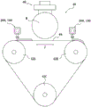
Here, the outline of the wire saw will be described with reference to fig. 2. The wire saw 40 includes a wire group 44, a workpiece holding mechanism 46, and a nozzle 200, the wire group 44 is configured to tension the wire between a plurality of rollers 42A, 42B, 42C in parallel and in a reciprocating manner, the workpiece holding mechanism 46 holds the workpiece W, and the nozzle 200 supplies the processing liquid to the wire group 44. The method of cutting a workpiece is roughly classified into a free abrasive grain method and a fixed abrasive grain method. In the free abrasive mode, the slurry including abrasive particles is continuously supplied from the nozzle 200 to the line group 44, and the line group 44 is reciprocated at high speed in the extending direction Z. At the same time, the workpiece W is moved in the push-in direction with respect to the wire group 44 by the workpiece holding mechanism 46. By the cutting action of the abrasive grains at this time, a plurality of wafers can be cut out simultaneously from the workpiece W. In the fixed abrasive grain method, since the slicing process is performed using a wire (fixed abrasive grain wire) to which abrasive grains are fixed by resin or plating, a coolant containing no abrasive grains is supplied from the nozzle 200 to the wire group 44. In addition, in fig. 2, a state where the wire group 44 moves from left to right in the drawing is depicted.
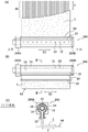
Here, as a nozzle 200 for ejecting the machining liquid to the wire group 44, a double pipe structure as shown in fig. 3(a) to (C) is known. The wire saw working fluid supply nozzle 200 shown in fig. 3 includes an inner tube 10 and an outer tube 20. The inner tube 10 extends linearly, and a plurality of holes 12 having the same diameter are provided along the extending direction E1. The outer tube 20 extends outside the inner tube 10 and is provided with a slit 22 of constant width at a position opposite to the hole 12 of the inner tube in the direction of extension E1 thereof. The machining liquid L is supplied into the inner tube 14, discharged into the outer tube through the plurality of holes 12 of the inner tube, and ejected through the slit 22. As shown in fig. 2 and 3, the workpiece and the nozzles 200 are located on the line group 44 so as to be orthogonal to the extending direction Z thereof. Therefore, the processing liquid L discharged from the slit 22 of the nozzle is supplied onto the line group 44 and then moves in the traveling direction of the line group 44, as shown in fig. 3 (a).
At this time, the discharge amount of the processing liquid from the slit 22 may vary along the extending direction E1 of the nozzle 200. For example, in the nozzle 200 shown in fig. 3, the machining liquid is supplied from one end 200A to the inner part 14 of the inner tube, and the other end 200B is sealed. In this case, it is understood that when the coolant is used as the machining fluid, the amount of coolant discharged per unit time from the holes 12 of the inner pipe is larger at the holes on the downstream side near the end 200B than at the holes on the upstream side near the end 200A. Therefore, as shown in fig. 3(a), the arrival position on the line group 44 of the coolant L ejected from the slits 22 is also farther on the downstream side than on the upstream side of the nozzle 200. On the other hand, when slurry is used as the working fluid, the discharge amount per unit time of the slurry from the hole 12 of the inner pipe is larger on the upstream side than on the downstream side.
As described above, if the discharge amount and the arrival position of the processing liquid from the slit 22 are not uniform in the extending direction E1 of the nozzle 200, there is caused a variation in processing accuracy such that the processing accuracy of the wafer cut by the upstream line and the processing accuracy of the wafer cut by the downstream line are different. Therefore, it is desirable to suppress such variations in the discharge amount and the arrival position due to the difference in the processing liquid. In the present specification, the end 200A side is hereinafter referred to as "upstream" and the end 200B side is hereinafter referred to as "downstream" in the flow of the processing liquid in the inner tube of the nozzle.
Patent document 1: japanese patent laid-open No. 7-195358.
Patent document 2: japanese patent laid-open No. 10-291212.
Disclosure of Invention
In view of the above-described problems, it is an object of the present invention to provide a wire saw machining liquid supply nozzle that can easily and accurately adjust the discharge amount of machining liquid in the extension direction of the wire saw machining liquid supply nozzle without being affected by the conditions of supply of the machining liquid into the nozzle, the state of the machining liquid, and the like, and that has a double pipe structure. The invention also provides a method for supplying a working fluid to a wire saw by using the working fluid supply nozzle for a wire saw.
The main technical means of the present invention that can achieve the above object are as follows.
The present invention provides a processing liquid supply nozzle for a wire saw, comprising an inner tube linearly extending and having a plurality of holes formed along an extending direction thereof, and an outer tube extending along an outer side of the inner tube and having a slit with a constant width formed at a position shifted from the holes of the inner tube along the extending direction thereof, wherein a processing liquid supplied into the inner tube is discharged into the outer tube through the plurality of holes of the inner tube and is then discharged into the wire saw through the slit of the outer tube, wherein the processing liquid supply nozzle for a wire saw has a double-tube structure, wherein the outer tube has holes formed at positions facing the plurality of holes of the inner tube, and the outer tube has holes formed at the plurality of holes thereof, respectively, bolts extending into the holes of the inner tube facing each other are attached to the holes of the outer tube, and the fixing positions of the bolts with respect to the holes of the outer tube are moved from the outside of the outer tube, thereby, the discharge amount of the machining liquid from each hole of the inner pipe can be individually adjusted, and the bolt is fixed to the hole of the outer pipe via a nut positioned in contact with the outer surface of the outer pipe.
Here, it is preferable that the outer tube is composed of an upper member including a plurality of holes of the outer tube and a lower member including the slit, and the upper member and the lower member are detachable.
Further, it is preferable that the bolt has a distal end portion having a diameter gradually decreasing toward the hole of the inner pipe.
Further, it is preferable that the bolt has a diameter equal to or larger than a diameter of the hole of the inner pipe.
The method for supplying a working fluid to a wire saw of the present invention uses a working fluid supply nozzle for a wire saw having an inner tube and an outer tube, the inner tube linearly extending and having a plurality of holes formed along an extending direction thereof, the outer tube extending along an outer side of the inner tube and having a slit formed along the extending direction thereof at a position shifted from the holes of the inner tube, the working fluid supply nozzle for a wire saw having a double tube structure, wherein the working fluid supplied to an inside of the inner tube is discharged to the inside of the outer tube through the plurality of holes of the inner tube and is then discharged to the wire saw through the slit of the outer tube, and is characterized in that the outer tube has holes formed at positions facing the plurality of holes of the inner tube, and bolts extending to the holes of the inner tube facing each other are attached to the plurality of holes of the outer tube, the bolt is fixed to the hole of the outer pipe via a nut positioned in contact with the outer surface of the outer pipe.
In one embodiment of the method, the wire saw working fluid supply nozzle supplies the working fluid from one end of the inner tube into the inner tube, and the other end of the inner tube is sealed. Preferably, in this case, the bolt is pushed in from the one end toward the other end.
In one embodiment of the method, the wire saw preferably includes a fixed abrasive wire, and the working fluid is a coolant containing no abrasive.
Effects of the invention
According to the wire saw working fluid supply nozzle and the method of supplying the wire saw with the working fluid of the present invention, the discharge amount of the working fluid in the extension direction of the wire saw working fluid supply nozzle can be adjusted with high accuracy and ease without being affected by the conditions of supplying the working fluid into the nozzle, the state of the working fluid, and the like.
Drawings
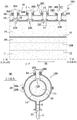
Fig. 1(a) is a partial cross-sectional view of a working fluid supply nozzle 100 for a wire saw according to an embodiment of the present invention, taken along the extending direction E1 of an inner tube and an outer tube. FIG. 1(B) is a sectional view taken along line I-I of FIG. 1 (A).
Fig. 2 is a schematic view showing a wire saw including a wire saw working fluid supply nozzle according to the present invention or a comparative example.
Fig. 3 is a diagram showing a working fluid supply nozzle 200 for a wire saw according to a comparative example, in which fig. 3(a) is a plan view, fig. 3(B) is a front view, and fig. 3(C) is a sectional view taken along line II-II of fig. 3 (B).
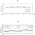
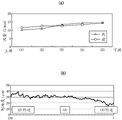
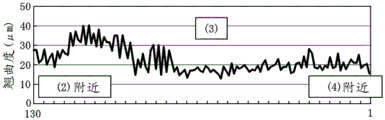
Fig. 4 is a graph showing the results of the examples, in which fig. 4(a) shows the flow rate distribution of the coolant along the extension direction of the wire saw working fluid supply nozzle, and fig. 4(B) shows the distribution of the warpage (Warp) of the wafer obtained by cutting the workpiece along the wire saw working fluid supply nozzle.
Fig. 5 is a graph showing the results of comparative example 1, fig. 5(a) is the same graph as fig. 4(a), and fig. 5(B) is the same graph as fig. 4 (B).
Fig. 6 is a graph showing the results of comparative example 2, which shows the distribution of warpage (Warp) of a wafer obtained by cutting a workpiece along a processing liquid supply nozzle for a wire saw.
Detailed Description
Hereinafter, embodiments of the present invention will be described with reference to the drawings.
The wire saw of the present embodiment including the wire saw working fluid supply nozzle 100 (hereinafter simply referred to as "nozzle 100") is the same as the wire saw 40 shown in fig. 2, for example, and therefore, the description thereof is omitted.
Next, the structure of the nozzle 100 will be described with reference to fig. 1(a) and 1 (B). The same reference numerals are used for the same structure and portions of the nozzle 100 as those of the nozzle 200 of the comparative example shown in fig. 3.
The nozzle 100 includes an inner tube 10 and an outer tube 20. The inner pipe 10 extends linearly, and a plurality of holes 12 having the same diameter are provided at equal intervals in the extending direction E1. In fig. 1, 4 holes 12A, 12B, 12C, and 12D are shown from the upstream side as a part of the plurality of holes. The outer tube 20 extends along the outside of the inner tube 10, and a slit 22 having a constant width is provided at a position opposite to the hole 12 of the inner tube in the extending direction E1. Therefore, the working fluid L supplied to the inside 14 of the inner tube is discharged into the inside 24 of the outer tube through the plurality of holes 12 of the inner tube, and is further discharged to the wire group 44 of the wire saw 40 through the slit 22 of the outer tube.
The technical solution of the nozzle 100 is as follows. First, the outer tube 20 is provided with holes 26A, 26B, 26C, and 26D at positions facing the plurality of holes 12A, 12B, 12C, and 12D of the inner tube, respectively. Bolts 30A, 30B, 30C, and 30D, which are rod-like members extending toward the holes 12A, 12B, 12C, and 12D of the facing inner tubes, are attached to the plurality of holes 26A, 26B, 26C, and 26D of the outer tubes, respectively. The outer tube has holes 26A, 26B, 26C, 26D with female threads cut on its inner surface and bolts 30A, 30B, 30C, 30D with male threads cut on their outer surface. Therefore, the bolts 30A, 30B, 30C, and 30D are slidable and fixable in the extending direction E2. Therefore, by moving the fixing positions of the bolts 30A, 30B, 30C, and 30D with respect to the holes 26A, 26B, 26C, and 26D of the outer tube from the outside of the outer tube 20, the discharge amounts of the machining liquids in the holes 12A, 12B, 12C, and 12D of the inner tube can be individually adjusted.
The technical significance and the effect of the technical scheme are explained together. As described above, the adjustment of the slit width 22 of the outer tube is insufficient to reduce the variation in the extending direction E1 in the discharge amount of the machining liquid from the slits 22, and the discharge amount must be made uniform in the extending direction E1 in advance at the stage of discharging the machining liquid from the hole 12 of the inner tube into the interior 24 of the outer tube. As a method for performing such adjustment with high accuracy and ease, the inventors of the present invention conceived that the size of the communication space between the inner tube 10 and the outer tube 20 is adjusted with respect to the hole by disposing a bolt 30 as a rod-like member in the vicinity of the hole 12 of the inner tube and by providing various fixing positions of the bolt 30. The "fixing position of the bolt to the hole of the outer tube" may be referred to as an amount of pushing the bolt into the outer tube, or may be referred to as a length of the bolt portion located inside the outer tube.
In the present embodiment, both end portions 100A, 100B of the nozzle 100 have the same structure as that of fig. 3. That is, the machining liquid is supplied from one end 100A of the nozzle 100 to the inside 14 of the inner tube, and the other end 100B is sealed. In the case of using the coolant as the machining liquid in this structure, as described above, the discharge amount of the machining liquid from the hole 12 of the inner pipe is increased in the order of the holes 12A, 12B, 12C, and 12D without the bolt 30. Therefore, as shown in fig. 1(a), the amount of insertion increases from one end 100A to the other end 100B, that is, in the order of bolts 30A, 30B, 30C, and 30D. As a result, variations in the discharge amounts of the machining liquid from the holes 12A, 12B, 12C, and 12D of the inner pipe can be suppressed with high accuracy. Therefore, variation in the processing accuracy of the wafer can be suppressed. In the case where only the end of the inner pipe is sealed and a small hole is present in the end of the outer pipe, the other end 100B may be pushed in by the bolts 30A, 30B, 30C, and 30D in this order.
Further, since the fixing position of the bolt 30 is changed from the outside of the nozzle 100, the adjustment can be easily performed. Further, even when the supply condition of the machining liquid into the nozzle 100 or the state of the machining liquid changes, the fine adjustment can be easily performed again, and the machining liquid supply condition can be adapted to various machining liquid supply conditions.
In fig. 1(a), the pushing amount is increased in the order of the bolts 30A, 30B, 30C, and 30D, but the present invention is not limited to this, and variation in the extending direction E1 of the discharge amount of the processing liquid may be suppressed in accordance with the mode of the nozzle and the processing liquid supply condition. For example, when the slurry is discharged as the processing liquid by using the nozzle 100 of fig. 1(a), if the bolt 30 is not provided, the amount of the slurry discharged per unit time from the hole 12 of the inner pipe is larger on the upstream side than on the downstream side. Therefore, in contrast to fig. 1(a), the amount of pushing may be made smaller in the order of bolts 30A, 30B, 30C, and 30D. The difference in the discharge amount unevenness between the case where the working fluid is a coolant and the case where the working fluid is a slurry is found experimentally, but one of the reasons is presumably that the slurry has a higher viscosity than the coolant, as compared with the case where the coolant has a lower viscosity.
The nozzle 100 of the present embodiment can be applied to both the case of ejecting the slurry in the free abrasive method and the case of ejecting the coolant in the fixed abrasive method. The conditions such as the kind of the slurry or the coolant, the supply flow rate of the nozzle to the inner pipe 14, and the like can be appropriately set. The cutting conditions such as the type of wire, the tension, and the running speed can also be set appropriately. However, since the coolant generally has a lower viscosity than the slurry, variation in the amount of discharge from the nozzle is likely to occur, and therefore the nozzle 100 of the present embodiment is particularly suitable for the fixed abrasive method. In addition, in the fixed abrasive grain system, since a coolant containing no abrasive grains is used, the coolant does not directly collide with the workpiece, and needs to be supplied to a position as close to the workpiece as possible. In this case, the nozzle is often inclined, and therefore, although the unevenness of the ejection amount is reliably generated in the state of the conventional nozzle, the unevenness can be corrected by the nozzle 100 of the present embodiment.
The material of the inner tube 10 is not particularly limited, and may be stainless steel, gold-plated iron, resin, or the like. As shown in fig. 1(B), the cross-sectional shape of the inner tube 10 perpendicular to the extending direction E1 can be circular, and the inner diameter can be 10 to 50 mm. The interval (pitch) of the holes 12 of the inner pipe may be 3 to 30mm, the shape of the holes 12 is preferably circular, and the diameter r1 may be 2 to 5 mm. Fig. 1(a) shows an example in which the holes 12 of the inner pipe are arranged at equal intervals, but the present invention is not limited to this. In the present invention, the phrase "the plurality of holes 12 have the same diameter" does not mean that the holes have the same diameter in a strict mathematical sense, and obviously allows dimensional tolerance in processing.
The material of the outer tube 20 is not particularly limited, and may be stainless steel, gold-plated iron, resin, or the like. As shown in fig. 1(B), the outer tube 20 may have a circular cross-sectional shape perpendicular to the extending direction E1, and may have an inner diameter of 14 to 54 mm. The width d of the slit 22 may be a certain value in the range of 1 to 5 mm. In addition, it is obvious that the width d of the slit 22 also allows dimensional tolerance during processing. The diameter of the hole 26 of the outer tube (i.e., the diameter measured at the bottom of the thread valley) is equal to or greater than the diameter r1 of the hole 12 of the inner tube. In fig. 1(a), the example in which the slit 22 is provided at a position opposite to the hole 12 of the inner pipe is illustrated, but the present invention is not limited thereto. Since the hole 30 is disposed at a position facing the hole of the inner tube, the slit cannot be provided, but the slit can be provided at an arbitrary position if the other position is displaced from the hole of the inner tube.
As shown in fig. 1(B), the outer tube 20 is composed of an upper part 20A including a hole 26 of the outer tube and a lower part 20B including a slit 22, and the upper part 20A and the lower part 20B are preferably detachable. The reason is as follows. The inner tube 10 and the outer tube 20 need to be periodically washed. In the case where the tip end of the bolt 30D enters the hole 12D of the inner pipe as in the bolt 30D of fig. 1(a), the bolt 30D needs to be temporarily retracted upward and the inner pipe 10 needs to be pulled out from the outer pipe 20, but in this case, it is complicated to adjust the bolt 30 again after washing. If the upper part 20A and the lower part 20B are detachably attached, the inner pipe 10 can be detached from the outer pipe 20 without moving the bolt 30, and adjustment of the bolt 30 again after washing is not necessary.
The type of the bolt 30 is not particularly limited, and examples thereof include a bolt, a hexagon bolt, a full-thread bolt, a flange bolt, a butterfly bolt, an eyelet bolt, and a hollow screw module (ホーローセット). The plurality of bolts 30 are identical in shape to each other. Further, the bolt 30 is liquid-tightly attached to the hole 26 of the outer tube. The bolt 30 is preferably of a size that is capable of completely blocking the bore 12 of the inner tube and is capable of being completely open. From this viewpoint, the diameter r2 of the bolt 30 (i.e., the diameter measured at the crest of the thread) is preferably equal to or larger than the diameter r1 of the hole 12 of the inner tube.
The bolt 30 preferably has a distal end portion 32 that tapers in diameter toward the bore 12 of the inner tube. This makes it possible to easily adjust the size of the communication space between the inner tube 10 and the outer tube 20. As shown in fig. 1(a) and 1(B), the tip portion 32 may be conical or hemispherical.
As shown in fig. 1(a) and 1(B), the bolt 30 is passed through a nut 34 located in contact with the outer surface of the outer tube 20. Is fixed relative to the bore 26 of the outer tube. When the bolt 30 is attached to the hole 26 of the outer tube without the nut 34, the bolt 30 may gradually loosen due to vibration of the nozzle 100 during the operation of supplying the working fluid to the wire saw. Thus, the fixing position of the bolt 30 to the hole 26 of the outer pipe is gradually changed, and the effect of suppressing variation in the discharge amount of the machining liquid from the hole of the inner pipe is not sufficiently obtained. Therefore, in the present embodiment, the bolt 30 is fixed to the hole 26 of the outer tube via the nut 34 located at a position contacting the outer surface of the outer tube 20. The hole 26 of the outer tube is also internally threaded, so that a tensile force acts between the portion defining the hole of the outer tube and the nut 34, and the bolt 30 can be prevented from loosening by an effect similar to that of a so-called double nut.
The type of the nut 34 is not particularly limited, and examples thereof include a hexagonal nut and a flange nut. The inner diameter of the nut 34 (i.e. the diameter measured at the bottom of the thread valleys) is the same as the diameter of the bore 26 of the outer tube already described.
Examples
(examples)
Using the wire saw shown in FIG. 2 including the nozzle shown in FIG. 1, an ingot of a silicon single crystal (diameter 300mm, length 150mm) was cut under the following cutting conditions.
< cutting Condition >
Line: fixed abrasive grain line
Wire diameter: 0.12mm (core wire)
Line tension: 20 to 30N
The linear traveling speed: 400 to 900 m/min (reciprocating)
Cooling agent: ethylene glycol-based coolant
Supply amount of coolant to the inside of the nozzle inner tube: 100L/min
Temperature of the coolant: 18-26 DEG C
The specification of the nozzle is as follows.
Nozzle length: 67.7cm
Inner diameter of inner tube: 22.5mm
Bore of inner tube: the number of the grooves is 52, the intervals are 12mm, and the diameter is 5mm
Inner diameter of outer tube: 27.5mm
Slit width: 2mm
Holes of the outer tube: the number, the interval and the diameter of the holes are the same as those of the holes of the inner pipe.
Bolt: bolt with hexagonal hole (end taper processing, length: 25mm, diameter: M6)
Nut: hexagon nut
The bolt increases the amount of thrust from the upstream side to the downstream side. The bolt is fixed to the hole of the outer tube via a nut disposed in contact with the outer surface of the outer tube.
Comparative example 1
Slicing of a silicon single crystal ingot (diameter 300mm, length 150mm) was carried out according to the same slicing conditions as in the examples using the wire saw shown in FIG. 2 including the nozzle shown in FIG. 3. The structure and specification of the nozzle are the same as those of the embodiment except that the hole of the outer tube, the bolt and the nut are not provided, and the outer tube member is not divided into the upper part and the lower part.
Comparative example 2
The silicon single crystal ingot (300 mm in diameter and 150mm in length) was cut under the same cutting conditions as in example 1 using the same nozzle as in example 1 except that no nut was used. The cutting process was started at the first bolt fixing position, and the wafer obtained by cutting the third ingot was used for the following evaluation of the process unevenness.
< measurement of flow quantity of coolant >
In example and comparative example 1, first, the coolant was discharged without tensioning the wire, and the discharge amount per unit time of the coolant from the nozzle was measured. Specifically, the measuring cup was placed at five positions at equal intervals from upstream to downstream in the extending direction of the nozzle, directly below the slit, and the discharge amount was measured. The discharge amount (flow rate) per minute at each measurement position is shown in fig. 4(a) for the example, and fig. 5(a) for comparative example 1. In the graph, the right nozzle in fig. 2 is shown as "inner", and the left nozzle is shown as "front".
In comparative example 1 shown in fig. 5(a), the coolant flow on the wire group increases as going from the upstream side to the downstream side. On the other hand, in the embodiment shown in fig. 4(a), such unevenness in coolant flow rate is suppressed.
< evaluation of coolant arrival position and evaluation of wafer processing unevenness >
Next, in examples, comparative examples 1 and 2, the wire was tensioned to cut the ingot.
The arrival positions of the coolant on the line in the extending direction of the line were visually confirmed, and in comparative example 1, the coolant reached a position farther downstream than the upstream side as shown in fig. 3, and the arrival positions were not uniform.
For all the wafers after cutting, warpage (warp) indicating warpage was measured using a flatness measuring apparatus (SBW, product of japan steel corporation). Fig. 4(B), 5(B), and 6 show graphs in which the total warpage (μm) of 130 wafers cut from the wafer cut from the line on the downstream side to the wafer cut from the line on the upstream side is aligned in the extending direction of the nozzle in the example, comparative example 1, and comparative example 2.
As shown in fig. 5(B), in comparative example 1, the warpage of the wafer cut by wire on the downstream side is smaller than that of the wafer cut by wire on the upstream side, and the processing accuracy is not uniform. On the other hand, as shown in fig. 4(B), in the embodiment, the unevenness of warp is suppressed as compared with the comparative example. Further, as shown in fig. 6, it was observed that in comparative example 2, since the bolt was not fixed by the nut, the machining accuracy was not uniform at the time of cutting the third ingot due to loosening of the bolt (i.e., change in the fixing position of the bolt).
Industrial applicability
According to the wire saw working fluid supply nozzle and the method of supplying the wire saw with the working fluid of the present invention, the adjustment of the discharge amount of the working fluid in the extension direction of the wire saw working fluid supply nozzle can be performed with high accuracy and easily without being affected by the conditions of supplying the working fluid into the nozzle, the state of the working fluid, and the like.
Description of the reference numerals
Processing liquid supply nozzle for 100 wire saw
One end of a working fluid supply nozzle for a 100A wire saw
The other end of the working fluid supply nozzle for 100B wire saw
10 inner pipe
12 bore of inner tube
14 inside of the inner tube
20 outer tube
20A Upper part
20B lower part
22 slit
24 inside the outer tube
26 holes of the outer tube
30 bolt
32 bolt end portion
34 nut
E1 extending direction of inner and outer tubes
Direction of extension of E2 bolt
r1 diameter of inner tube hole
r2 bolt diameter
d width of the slit.
Claims (8)
1. A working fluid supply nozzle for a wire saw, comprising an inner tube linearly extending and having a plurality of holes formed along an extending direction thereof, and an outer tube extending outside the inner tube and having slits formed along an extending direction thereof at positions shifted from the holes of the inner tube, wherein a working fluid supplied into the inner tube is discharged into the outer tube through the plurality of holes of the inner tube and is then discharged toward the wire saw through the slits of the outer tube, wherein the working fluid supply nozzle for a wire saw has a double-tube structure,
holes are respectively arranged at the positions opposite to the plurality of holes of the inner pipe at the outer pipe,
bolts extending toward the holes of the inner pipe facing each other are attached to the plurality of holes of the outer pipe, respectively, and the fixing positions of the bolts with respect to the holes of the outer pipe are moved from the outside of the outer pipe, whereby the discharge amount of the machining liquid from each hole of the inner pipe can be individually adjusted,
the bolt is fixed to the hole of the outer tube via a nut located in a position contacting the outer surface of the outer tube.
2. The processing liquid supply nozzle for wire saw according to claim 1,
the outer tube is composed of an upper member including a plurality of holes of the outer tube and a lower member including the slit, and the upper member and the lower member are detachable.
3. The processing liquid supply nozzle for wire saw according to claim 1 or 2,
the bolt has a distal end portion with a diameter gradually decreasing toward the hole of the inner pipe.
4. The processing liquid supply nozzle for wire saw according to claim 1 or 2,
the diameter of the bolt is equal to or larger than the diameter of the hole of the inner pipe.
5. The processing liquid supply nozzle for wire saw according to claim 3,
the diameter of the bolt is equal to or larger than the diameter of the hole of the inner pipe.
6. A method for supplying a working fluid to a wire saw, using a working fluid supply nozzle for a wire saw having an inner tube and an outer tube, the inner tube extending linearly and having a plurality of holes formed along an extending direction thereof, the outer tube extending outside the inner tube and having slits formed along the extending direction thereof at positions offset from the holes of the inner tube, the working fluid supply nozzle for a wire saw having a double tube structure,
in the method for supplying a working fluid to a wire saw, the working fluid supplied to the inside of the inner tube is discharged to the inside of the outer tube through the plurality of holes of the inner tube, and is further discharged to the wire saw through the slit of the outer tube,
holes are respectively arranged at the positions opposite to the plurality of holes of the inner pipe at the outer pipe,
bolts extending toward the holes of the inner pipe facing each other are attached to the plurality of holes of the outer pipe, respectively, and the discharge amount of the machining liquid from each hole of the inner pipe is individually adjusted by moving the fixing position of the bolt with respect to the hole of the outer pipe from the outside of the outer pipe,
the bolt is fixed to the hole of the outer tube via a nut located in a position contacting the outer surface of the outer tube.
7. The method for supplying a working fluid to a wire saw according to claim 6,
the wire saw working fluid supply nozzle supplies the working fluid from one end of the inner tube into the inner tube, and the other end of the inner tube is sealed,
in this case, the bolt is pushed in from the one end toward the other end.
8. The method for supplying a working fluid to a wire saw according to claim 6 or 7,
the wire saw includes a fixed abrasive wire, and the working fluid is a coolant containing no abrasive particles.
Priority Applications (1)
| Application Number | Priority Date | Filing Date | Title |
|---|---|---|---|
| CN201811140979.7A CN110962248A (en) | 2018-09-28 | 2018-09-28 | Machining liquid supply nozzle for wire saw and method for supplying machining liquid to wire saw |
Applications Claiming Priority (1)
| Application Number | Priority Date | Filing Date | Title |
|---|---|---|---|
| CN201811140979.7A CN110962248A (en) | 2018-09-28 | 2018-09-28 | Machining liquid supply nozzle for wire saw and method for supplying machining liquid to wire saw |
Publications (1)
| Publication Number | Publication Date |
|---|---|
| CN110962248A true CN110962248A (en) | 2020-04-07 |
Family
ID=70027797
Family Applications (1)
| Application Number | Title | Priority Date | Filing Date |
|---|---|---|---|
| CN201811140979.7A Pending CN110962248A (en) | 2018-09-28 | 2018-09-28 | Machining liquid supply nozzle for wire saw and method for supplying machining liquid to wire saw |
Country Status (1)
| Country | Link |
|---|---|
| CN (1) | CN110962248A (en) |
Citations (17)
| Publication number | Priority date | Publication date | Assignee | Title |
|---|---|---|---|---|
| JPH07195358A (en) * | 1993-12-29 | 1995-08-01 | Nippei Toyama Corp | Slurry supply method and nozzle of wire saw |
| JPH10291212A (en) * | 1997-04-18 | 1998-11-04 | Shin Etsu Handotai Co Ltd | Slicing device for semiconductor ingot |
| JP2000084824A (en) * | 1998-09-11 | 2000-03-28 | Tokyo Seimitsu Co Ltd | Slurry supplying method for wire saw and its device |
| JP2004066389A (en) * | 2002-08-06 | 2004-03-04 | Sharp Corp | Slicing method for ingot and wire saw cutting device |
| US20040084042A1 (en) * | 2002-11-06 | 2004-05-06 | Seh America, Inc. | Apparatus, system and method for cutting a crystal ingot |
| JP2006326756A (en) * | 2005-05-26 | 2006-12-07 | Mitsubishi Electric Corp | Slurry supply mechanism of multi-wire saw |
| US20110048396A1 (en) * | 2009-08-31 | 2011-03-03 | Sumco Corporation | Wire saw device |
| KR20110090016A (en) * | 2010-02-02 | 2011-08-10 | 주식회사 엘지실트론 | An apparatus and a method for slicing a ingot |
| CN102729347A (en) * | 2011-04-05 | 2012-10-17 | 硅电子股份公司 | Method for cutting workpiece with wire saw |
| JP2013086233A (en) * | 2011-10-20 | 2013-05-13 | Sumco Corp | Wire saw device and work plate used for the device |
| CN202964939U (en) * | 2012-12-21 | 2013-06-05 | 天津英利新能源有限公司 | Fretsaw cutter of silicon blocks |
| KR20140088714A (en) * | 2013-01-03 | 2014-07-11 | 주식회사 엘지실트론 | An apparatus for slicing an ingot |
| CN203712893U (en) * | 2013-12-31 | 2014-07-16 | 天津英利新能源有限公司 | Slurry baffle for silicon wafer multi-wire sawing machine |
| CN203792547U (en) * | 2014-03-20 | 2014-08-27 | 常州兆晶光能有限公司 | Main roller sand blasting device for multi-wire sawing machine |
| JP2015030082A (en) * | 2013-08-06 | 2015-02-16 | 株式会社Sumco | Working liquid supply nozzle for wire saws, and working liquid supply method to wire saws |
| CN107206628A (en) * | 2015-01-26 | 2017-09-26 | Lg矽得荣株式会社 | Saw blade cutting equipment |
| CN107427986A (en) * | 2015-05-01 | 2017-12-01 | 信越半导体株式会社 | Wire sawing apparatus |
-
2018
- 2018-09-28 CN CN201811140979.7A patent/CN110962248A/en active Pending
Patent Citations (17)
| Publication number | Priority date | Publication date | Assignee | Title |
|---|---|---|---|---|
| JPH07195358A (en) * | 1993-12-29 | 1995-08-01 | Nippei Toyama Corp | Slurry supply method and nozzle of wire saw |
| JPH10291212A (en) * | 1997-04-18 | 1998-11-04 | Shin Etsu Handotai Co Ltd | Slicing device for semiconductor ingot |
| JP2000084824A (en) * | 1998-09-11 | 2000-03-28 | Tokyo Seimitsu Co Ltd | Slurry supplying method for wire saw and its device |
| JP2004066389A (en) * | 2002-08-06 | 2004-03-04 | Sharp Corp | Slicing method for ingot and wire saw cutting device |
| US20040084042A1 (en) * | 2002-11-06 | 2004-05-06 | Seh America, Inc. | Apparatus, system and method for cutting a crystal ingot |
| JP2006326756A (en) * | 2005-05-26 | 2006-12-07 | Mitsubishi Electric Corp | Slurry supply mechanism of multi-wire saw |
| US20110048396A1 (en) * | 2009-08-31 | 2011-03-03 | Sumco Corporation | Wire saw device |
| KR20110090016A (en) * | 2010-02-02 | 2011-08-10 | 주식회사 엘지실트론 | An apparatus and a method for slicing a ingot |
| CN102729347A (en) * | 2011-04-05 | 2012-10-17 | 硅电子股份公司 | Method for cutting workpiece with wire saw |
| JP2013086233A (en) * | 2011-10-20 | 2013-05-13 | Sumco Corp | Wire saw device and work plate used for the device |
| CN202964939U (en) * | 2012-12-21 | 2013-06-05 | 天津英利新能源有限公司 | Fretsaw cutter of silicon blocks |
| KR20140088714A (en) * | 2013-01-03 | 2014-07-11 | 주식회사 엘지실트론 | An apparatus for slicing an ingot |
| JP2015030082A (en) * | 2013-08-06 | 2015-02-16 | 株式会社Sumco | Working liquid supply nozzle for wire saws, and working liquid supply method to wire saws |
| CN203712893U (en) * | 2013-12-31 | 2014-07-16 | 天津英利新能源有限公司 | Slurry baffle for silicon wafer multi-wire sawing machine |
| CN203792547U (en) * | 2014-03-20 | 2014-08-27 | 常州兆晶光能有限公司 | Main roller sand blasting device for multi-wire sawing machine |
| CN107206628A (en) * | 2015-01-26 | 2017-09-26 | Lg矽得荣株式会社 | Saw blade cutting equipment |
| CN107427986A (en) * | 2015-05-01 | 2017-12-01 | 信越半导体株式会社 | Wire sawing apparatus |
Non-Patent Citations (1)
| Title |
|---|
| 吴卓等: "《画法几何及机械制图》", 31 August 2018, 北京:北京理工大学出版社 * |
Similar Documents
| Publication | Publication Date | Title |
|---|---|---|
| US6889684B2 (en) | Apparatus, system and method for cutting a crystal ingot | |
| EP1724820B1 (en) | Two-fluid nozzle for cleaning substrate and substrate cleaning device | |
| JP5515593B2 (en) | Method for cutting silicon ingot with wire saw and wire saw | |
| SG185192A1 (en) | Method for cutting workpiece with wire saw | |
| JPH1052816A (en) | Wire-type cutting method | |
| US10589446B2 (en) | Wire saw apparatus | |
| US20120132188A1 (en) | Holding/cleaning device and method for the zonal cleaning of sawed wafers | |
| CN110962248A (en) | Machining liquid supply nozzle for wire saw and method for supplying machining liquid to wire saw | |
| KR101590833B1 (en) | Nozzle for supplying working liquid for wire saw and method for supplying working liquid to wire saw | |
| EP2621699B1 (en) | Sawing apparatus of single crystal ingot | |
| JP3976556B2 (en) | Wire saw | |
| US9597703B2 (en) | Slit nozzle | |
| JP2015168030A (en) | Wire electric discharge machining apparatus, thin plate manufacturing method, and semiconductor wafer manufacturing method | |
| JP2008213103A (en) | Working fluid feeding device of wire saw | |
| KR20230002374A (en) | Two-material shaft nozzle with reduced clogging tendency | |
| US11752665B2 (en) | Slurry sprayers, adjustable supports for same, and methods for slicing a silicon ingot | |
| KR20140080731A (en) | Device for manufacturing amorphous strip | |
| TW202039149A (en) | Workpiece cutting method and workpiece cutting device | |
| JP2006263547A (en) | Water jet nozzle device | |
| CN104552627A (en) | Semiconductor wire saw including a nozzle for generating a fluid jet | |
| KR101505748B1 (en) | Coolant-jetting apparatus | |
| JP7311446B2 (en) | Slit nozzle and substrate processing equipment | |
| TW201143901A (en) | Slit nozzle and wire saw system comprising the same | |
| CZ20022365A3 (en) | Apparatus and method for cutting up materials | |
| CN112275703A (en) | Water jet cutter structure utilizing coanda effect |
Legal Events
| Date | Code | Title | Description |
|---|---|---|---|
| PB01 | Publication | ||
| PB01 | Publication | ||
| SE01 | Entry into force of request for substantive examination | ||
| SE01 | Entry into force of request for substantive examination | ||
| WD01 | Invention patent application deemed withdrawn after publication |
Application publication date: 20200407 |
|
| WD01 | Invention patent application deemed withdrawn after publication |