CN110858552B - Bonding equipment and bonding method - Google Patents
Bonding equipment and bonding method Download PDFInfo
- Publication number
- CN110858552B CN110858552B CN201810973550.XA CN201810973550A CN110858552B CN 110858552 B CN110858552 B CN 110858552B CN 201810973550 A CN201810973550 A CN 201810973550A CN 110858552 B CN110858552 B CN 110858552B
- Authority
- CN
- China
- Prior art keywords
- bonded
- bonding
- wafer
- chip
- chips
- Prior art date
- Legal status (The legal status is an assumption and is not a legal conclusion. Google has not performed a legal analysis and makes no representation as to the accuracy of the status listed.)
- Active
Links
Images


Classifications
-
- H—ELECTRICITY
- H10—SEMICONDUCTOR DEVICES; ELECTRIC SOLID-STATE DEVICES NOT OTHERWISE PROVIDED FOR
- H10P—GENERIC PROCESSES OR APPARATUS FOR THE MANUFACTURE OR TREATMENT OF DEVICES COVERED BY CLASS H10
- H10P72/00—Handling or holding of wafers, substrates or devices during manufacture or treatment thereof
- H10P72/04—Apparatus for manufacture or treatment
-
- H—ELECTRICITY
- H10—SEMICONDUCTOR DEVICES; ELECTRIC SOLID-STATE DEVICES NOT OTHERWISE PROVIDED FOR
- H10P—GENERIC PROCESSES OR APPARATUS FOR THE MANUFACTURE OR TREATMENT OF DEVICES COVERED BY CLASS H10
- H10P10/00—Bonding of wafers, substrates or parts of devices
- H10P10/12—Bonding of semiconductor wafers or semiconductor substrates to semiconductor wafers or semiconductor substrates
- H10P10/128—Bonding of semiconductor wafers or semiconductor substrates to semiconductor wafers or semiconductor substrates by direct semiconductor to semiconductor bonding
Landscapes
- Die Bonding (AREA)
- Wire Bonding (AREA)
Abstract
本发明实施例公开了一种键合设备和键合方法。该键合设备包括:第一键合模块和第二键合模块;所述第一键合模块用于将多个待键合芯片排布于待键合晶圆上,并对所述多个待键合芯片和所述待键合晶圆进行预键合;所述第二键合模块用于对预键合后的所述多个待键合芯片和所述待键合晶圆进行永久键合。本发明实施例的方案提高了芯片键合的产率。

The embodiments of the present invention disclose a bonding device and a bonding method. The bonding equipment includes: a first bonding module and a second bonding module; the first bonding module is used for arranging a plurality of chips to be bonded on a wafer to be bonded, and for the plurality of chips to be bonded The chip to be bonded and the wafer to be bonded are pre-bonded; the second bonding module is used to permanently perform the pre-bonding of the plurality of chips to be bonded and the wafer to be bonded Bond. The solutions of the embodiments of the present invention improve the yield of die bonding.
Description
技术领域technical field
本发明实施例涉及键合技术,尤其涉及一种键合设备和键合方法。The embodiments of the present invention relate to bonding technology, and in particular, to a bonding device and a bonding method.
背景技术Background technique
由于电子产品轻、薄和小型化的发展趋势,使得芯片键合技术的应用日益增多。键合技术能够在不缩小线宽的情况下,在有限面积内进行最大程度的芯片叠加与整合,同时缩减晶片封装体积与线路传导长度,进而提升晶片传输效率。芯片-晶圆键合技术(Chip-to-wafer,C2W)可以保证更高的产品良率并可以满足Fan-Out工艺的封装需求,但对于金属键合、阳极键合和热直接键合等工艺时间较长的永久键合工艺,单个芯片键合时间过长导致设备产率低。Due to the development trend of light, thin and miniaturized electronic products, the application of chip bonding technology is increasing day by day. Bonding technology can maximize chip stacking and integration within a limited area without reducing the line width, while reducing the chip package volume and line conduction length, thereby improving chip transfer efficiency. Chip-to-wafer (C2W) technology can ensure higher product yield and can meet the packaging requirements of Fan-Out process, but for metal bonding, anodic bonding and thermal direct bonding, etc. The permanent bonding process with long process time and the long bonding time of a single chip lead to low equipment yield.
发明内容SUMMARY OF THE INVENTION
本发明提供一种键合设备和键合方法,提高Fan-Out键合工艺中永久键合工况的键合效率以提高芯片键合的产率。The invention provides a bonding device and a bonding method, which can improve the bonding efficiency of permanent bonding conditions in the Fan-Out bonding process to improve the yield of chip bonding.
第一方面,本发明实施例提供了一种键合设备,该设备包括:In a first aspect, an embodiment of the present invention provides a bonding device, the device comprising:
第一键合模块和第二键合模块;a first bonding module and a second bonding module;
所述第一键合模块用于将多个待键合芯片排布于待键合晶圆上,并对所述多个待键合芯片和所述待键合晶圆进行预键合;The first bonding module is used for arranging a plurality of chips to be bonded on the wafer to be bonded, and pre-bonding the plurality of chips to be bonded and the wafer to be bonded;
所述第二键合模块用于对预键合后的所述多个待键合芯片和所述待键合晶圆进行永久键合。The second bonding module is used to permanently bond the pre-bonded chips to be bonded and the wafer to be bonded.
可选的,所述第一键合模块包括转台、键合手和预键合台;Optionally, the first bonding module includes a turntable, a bonding hand and a pre-bonding stage;
所述转台用于放置所述多个待键合芯片,并将所述多个待键合芯片转移到键合手的芯片拾取位;The turntable is used for placing the plurality of chips to be bonded, and transferring the plurality of chips to be bonded to the chip pick-up position of the bonding hand;
所述预键合台用于放置待键合晶圆;The pre-bonding stage is used for placing the wafers to be bonded;
所述键合手用于从所述芯片拾取位获取所述待键合芯片,对所述待键合芯片进行加热,并将所述待键合芯片放置于所述待键合晶圆,以对所述待键合芯片和所述待键合晶圆进行预键合。The bonding hand is used to obtain the chip to be bonded from the chip pickup position, heat the chip to be bonded, and place the chip to be bonded on the wafer to be bonded to The chip to be bonded and the wafer to be bonded are pre-bonded.
可选的,所述第一键合模块还包括第一测量单元和第三测量单元,或者,所述第一键合模块还包括、第二测量单元和第三测量单元,或者所述第一键合模块还包括第一测量单元、第二测量单元和第三测量单元;所述第一测量单元用于测量所述待键合芯片在所述转台的第一位置;Optionally, the first bonding module further includes a first measurement unit and a third measurement unit, or the first bonding module further includes a second measurement unit and a third measurement unit, or the first measurement unit The bonding module further includes a first measurement unit, a second measurement unit and a third measurement unit; the first measurement unit is used to measure the first position of the chip to be bonded on the turntable;
所述第二测量单元用于测量所述待键合芯片在所述键合手上的第二位置;The second measuring unit is used to measure the second position of the chip to be bonded on the bonding hand;
所述第三测量单元用于测量所述待键合晶圆在所述预键合台的第三位置;The third measuring unit is used to measure the third position of the wafer to be bonded on the pre-bonding stage;
所述预键合台还用于根据所述第一位置和所述第三位置,或者根据所述第二位置和所述第三位置调节所述待键合晶圆的位置。The pre-bonding stage is further configured to adjust the position of the wafer to be bonded according to the first position and the third position, or according to the second position and the third position.
可选的,所述键合手为转盘式或直线式。Optionally, the bonding hand is a rotary or linear type.
可选的,所述第二键合模块包括传输手和永久键合单元;Optionally, the second bonding module includes a transmission hand and a permanent bonding unit;
所述传输手用于由所述第一键合模块获取预键合后的待键合芯片和待键合晶圆,并将所述待键合芯片和所述待键合晶圆放置于所述永久键合单元;The transfer hand is used to obtain the pre-bonded chips to be bonded and the wafers to be bonded from the first bonding module, and to place the chips to be bonded and the wafers to be bonded on the the permanent bonding unit;
所述永久键合单元用于对所述待键合芯片和所述待键合晶圆进行永久键合。The permanent bonding unit is used for permanently bonding the chip to be bonded and the wafer to be bonded.
可选的,所述永久键合单元包括真空腔以及设置于所述真空腔内的压盘和键合底座;Optionally, the permanent bonding unit includes a vacuum chamber, a pressing plate and a bonding base disposed in the vacuum chamber;
所述键合底座用于放置所述待键合晶圆和所述待键合芯片;the bonding base is used for placing the wafer to be bonded and the chip to be bonded;
所述压盘用于对所述待键合晶圆和所述待键合芯片加热加压,以进行永久键合。The platen is used for heating and pressing the to-be-bonded wafer and the to-be-bonded chip for permanent bonding.
可选的,所述永久键合单元的个数大于或等于2。Optionally, the number of the permanent bonding units is greater than or equal to 2.
可选的,该设备还包括:Optionally, the device also includes:
芯片获取模块,用于获取待键合芯片并将所述待键合芯片转移到所述第一键合模块。The chip acquisition module is used for acquiring the chips to be bonded and transferring the chips to be bonded to the first bonding module.
第二方面,本发明实施例还提供了一种键合方法,该键合方法包括:In a second aspect, an embodiment of the present invention also provides a bonding method, the bonding method comprising:
通过第一键合模块将多个待键合芯片排布于待键合晶圆上,并对所述多个待键合芯片和所述待键合晶圆进行预键合;Arranging a plurality of chips to be bonded on the wafer to be bonded through the first bonding module, and pre-bonding the plurality of chips to be bonded and the wafer to be bonded;
通过第二键合模块对预键合后的所述多个待键合芯片和所述待键合晶圆进行永久键合。The pre-bonded chips to be bonded and the wafer to be bonded are permanently bonded by the second bonding module.
可选的,所述第一键合模块包括转台、键合手和预键合台,则通过第一键合模块将多个待键合芯片排布于待键合晶圆上,并对所述多个待键合芯片和所述待键合晶圆进行预键合,包括:Optionally, the first bonding module includes a turntable, a bonding hand and a pre-bonding stage, then the first bonding module arranges a plurality of chips to be bonded on the wafer to be bonded, and performs all The plurality of chips to be bonded and the wafer to be bonded are pre-bonded, including:
测量所述待键合芯片在转台的第一位置;measuring the first position of the chip to be bonded on the turntable;
测量所述待键合晶圆在预键合台的第三位置;measuring the third position of the wafer to be bonded on the pre-bonding stage;
根据所述第一位置和所述第三位置调节所述待键合晶圆的位置;Adjust the position of the wafer to be bonded according to the first position and the third position;
或者,or,
测量所述待键合芯片在键合手上的第二位置;measuring the second position of the chip to be bonded on the bonding hand;
测量所述待键合晶圆在预键合台的第三位置;measuring the third position of the wafer to be bonded on the pre-bonding stage;
根据所述第二位置和所述第三位置调节所述待键合晶圆的位置。The position of the wafer to be bonded is adjusted according to the second position and the third position.
可选的,通过第一键合模块将多个待键合芯片排布于待键合晶圆上,并对所述多个待键合芯片和所述待键合晶圆进行预键合,包括:Optionally, the plurality of chips to be bonded are arranged on the wafer to be bonded by the first bonding module, and the plurality of chips to be bonded and the wafer to be bonded are pre-bonded, include:
对所述待键合芯片进行加热,以对所述待键合芯片和所述待键合晶圆进行预键合。The chip to be bonded is heated to pre-bond the chip to be bonded and the wafer to be bonded.
可选的,所述第二键合模块包括传输手和至少两个永久键合单元,则通过第二键合模块对预键合后的所述多个待键合芯片和所述待键合晶圆进行永久键合,包括:Optionally, the second bonding module includes a transmission hand and at least two permanent bonding units, then the pre-bonded chips to be bonded and the chips to be bonded are pre-bonded by the second bonding module. Wafers are permanently bonded, including:
通过传输手将预键合后的所述多个待键合芯片和所述待键合晶圆传输到空闲的永久键合单元,以对所述多个待键合芯片和所述待键合晶圆进行永久键合。The pre-bonded chips to be bonded and the wafers to be bonded are transferred to an idle permanent bonding unit by a transfer hand, so that the chips to be bonded and the wafers to be bonded are transferred to the idle permanent bonding unit. The wafers are permanently bonded.
本发明实施例通过第一键合模块将多个待键合芯片排布于同一待键合晶圆并进行预键合,并通过第二键合模块对预键合后的多个待键合芯片和待键合晶圆进行永久键合,使得一次永久键合工艺可以实现对多个待键合芯片的键合,提高Fan-Out键合工艺中永久键合工况的键合效率以提高键合产率,并且预键合用时较短,永久键合用时较长,通过第一键合模块对多个待键合芯片进行排布和预键合可以增长第一键合模块的工艺时长,使得第一键合模块和第二键合模块工艺时间相匹配,进一步提高键合设备的键合产率。In the embodiment of the present invention, a plurality of chips to be bonded are arranged on the same wafer to be bonded and pre-bonded by a first bonding module, and a plurality of chips to be bonded after pre-bonding are pre-bonded by a second bonding module The chip and the wafer to be bonded are permanently bonded, so that one permanent bonding process can realize the bonding of multiple chips to be bonded, and improve the bonding efficiency of permanent bonding conditions in the Fan-Out bonding process. Bonding yield, and the pre-bonding time is short, and the permanent bonding time is long. Arranging and pre-bonding multiple chips to be bonded through the first bonding module can increase the process time of the first bonding module. , so that the process times of the first bonding module and the second bonding module are matched, and the bonding yield of the bonding equipment is further improved.
附图说明Description of drawings
图1是本发明实施例提供的一种键合设备的示意图;1 is a schematic diagram of a bonding device provided in an embodiment of the present invention;
图2是本发明实施例提供的一种键合设备的正视图;2 is a front view of a bonding device provided by an embodiment of the present invention;
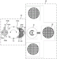
图3是本发明实施例提供的一种键合设备的俯视图;3 is a top view of a bonding device provided by an embodiment of the present invention;
图4是本发明实施例提供一种预键合台的示意图;4 is a schematic diagram of a pre-bonding stage provided by an embodiment of the present invention;
图5是本发明实施例提供的一种第一键合模块的正视图;5 is a front view of a first bonding module provided by an embodiment of the present invention;
图6是本发明实施例提供的一种第一键合模块的俯视图;6 is a top view of a first bonding module according to an embodiment of the present invention;
图7是本发明实施例提供的一种永久键合单元的示意图;7 is a schematic diagram of a permanent bonding unit provided by an embodiment of the present invention;
图8是本发明实施例提供的又一种键合设备的俯视图;8 is a top view of another bonding device provided by an embodiment of the present invention;
图9是本发明实施例提供的又一种键合设备的正视图;9 is a front view of another bonding device provided by an embodiment of the present invention;
图10是本发明实施例提供的又一种键合设备的俯视图;10 is a top view of another bonding device provided by an embodiment of the present invention;
图11是本发明实施例提供的一种键合设备的工作流程图;11 is a working flow diagram of a bonding device provided by an embodiment of the present invention;
图12是本发明实施例提供的一种键合方法的示意图。FIG. 12 is a schematic diagram of a bonding method provided by an embodiment of the present invention.
具体实施方式Detailed ways
下面结合附图和实施例对本发明作进一步的详细说明。可以理解的是,此处所描述的具体实施例仅仅用于解释本发明,而非对本发明的限定。另外还需要说明的是,为了便于描述,附图中仅示出了与本发明相关的部分而非全部结构。The present invention will be further described in detail below in conjunction with the accompanying drawings and embodiments. It should be understood that the specific embodiments described herein are only used to explain the present invention, but not to limit the present invention. In addition, it should be noted that, for the convenience of description, the drawings only show some but not all structures related to the present invention.
本实施例提供了一种键合设备,图1是本发明实施例提供的一种键合设备的示意图,参考图1,该键合设备包括:This embodiment provides a bonding device. FIG. 1 is a schematic diagram of a bonding device provided by an embodiment of the present invention. Referring to FIG. 1 , the bonding device includes:
第一键合模块10和第二键合模块20;the
第一键合模块10用于将多个待键合芯片排布于待键合晶圆上,并对多个待键合芯片和待键合晶圆进行预键合;The
第二键合模块20用于对预键合后的多个待键合芯片和待键合晶圆进行永久键合。The
其中,第一键合模块10可以根据待键合芯片的尺寸将多个待键合芯片排布于待键合晶圆上,并对待键合芯片和待键合晶圆进行预键合。同一待键合晶圆上排布的待键合芯片的个数可以根据芯片尺寸、晶圆尺寸、永久键合工艺的时长以及一个待键合芯片的预键合工艺时长确定。The
本实施例通过第一键合模块将多个待键合芯片排布于同一待键合晶圆并进行预键合,并通过第二键合模块对预键合后的多个待键合芯片和待键合晶圆进行永久键合,使得一次永久键合工艺可以实现对多个待键合芯片的键合,提高Fan-Out键合工艺中永久键合工况的键合效率以提高键合产率,并且预键合用时较短,永久键合用时较长,通过第一键合模块对多个待键合芯片进行排布和预键合可以增长第一键合模块的工艺时长,使得第一键合模块和第二键合模块工艺时间相匹配,进一步提高键合设备的键合产率。In this embodiment, multiple chips to be bonded are arranged on the same wafer to be bonded by the first bonding module and pre-bonded, and the pre-bonded multiple chips to be bonded are pre-bonded by the second bonding module Permanently bond with the wafer to be bonded, so that one permanent bonding process can realize the bonding of multiple chips to be bonded, and improve the bonding efficiency of permanent bonding conditions in the Fan-Out bonding process. In addition, the pre-bonding time is short, and the permanent bonding time is long. Arranging and pre-bonding multiple chips to be bonded through the first bonding module can increase the process time of the first bonding module. The process times of the first bonding module and the second bonding module are matched, and the bonding yield of the bonding equipment is further improved.
图2是本发明实施例提供的一种键合设备的正视图,图3是本发明实施例提供的一种键合设备的俯视图,可选的,参考图2和图3,第一键合模10包括转台11、键合手12和预键合台13;FIG. 2 is a front view of a bonding device provided by an embodiment of the present invention, and FIG. 3 is a top view of a bonding device provided by an embodiment of the present invention. Optionally, referring to FIGS. 2 and 3 , the first bonding The
转台11用于放置多个待键合芯片101,并将多个待键合芯片101转移到键合手12的芯片拾取位POSD;The
预键合台13用于放置待键合晶圆102;The
键合手12用于从芯片拾取位POSD获取待键合芯片101,对待键合芯片101进行加热,并将待键合芯片101放置于待键合晶圆102,以对待键合芯片101和待键合晶圆102进行预键合。The
具体的,键合手12获取到待键合芯片101后可以对待键合芯片101进行加热,示例性的可以在预热位POSG进行加热,使待键合芯片101放置于待键合晶圆102时保持加热状态,键合手12将待键合芯片101放置于待键合晶圆102时对其进行预键合,使待键合芯片101固定于待键合晶圆102上。Specifically, the
可选的,第一键合模块10还包括第一测量单元14和第三测量单元16,或者,第一键合模块10还包括第二测量单元15和第三测量单元16,或者,第一键合模块10还包括第一测量单元14、第二测量单元15和第三测量单元16:Optionally, the
第一测量单元14用于测量待键合芯片101在转台11的第一位置;The
第二测量单元15用于测量待键合芯片101在键合手12上的第二位置;The
第三测量单元16用于测量待键合晶圆102在预键合台13的第三位置;The
预键合台13还用于根据第一位置和第三位置,或者根据第二位置和第三位置调节待键合晶圆102的位置。The
具体的,第一测量单元14和第二测量单元15可以根据不同的工艺状况选择性布置,若待键合芯片101的对位标记朝上(chip up),则只需要设置第一测量单元14和第三测量单元16,预键合台13根据第一位置和第三位置将待键合晶圆102调整到与待键合芯片101匹配的位置;若待键合芯片101的对位标记朝下(chip down),则只需要设置第二测量单元15和第三测量单元16,预键合台13根据第二位置和第三位置将待键合晶圆102调整到与待键合芯片101匹配的位置;为了提高工艺适应性也可以同时设置第一测量单元14、第二测量单元15和第三测量单元16,根据不同的工况预键合台13根据第一位置和第三位置,或者根据第二位置和第三位置将待键合晶圆102调整到与待键合芯片101匹配的位置,使待键合芯片101放置于待键合晶圆102时位置精度更高,从而提高键合精度。Specifically, the
图4是本发明实施例提供一种预键合台的示意图,可选的,参考图4,预键合台13包括:冷热台131、运动台132和大理石底座133。运动台132用于驱动冷热台131运动以调整待键合晶圆102的位置,冷热台131用于固定待键合晶圆102和待键合芯片101,并在预键合时加热待键合晶圆102,在其余时间冷却待键合晶圆102。FIG. 4 is a schematic diagram of a pre-bonding stage provided by an embodiment of the present invention. Optionally, referring to FIG. 4 , the
图5是本发明实施例提供的一种第一键合模块的正视图,图6是本发明实施例提供的一种第一键合模块的俯视图,可选的,参考图2、图3、图5和图6,键合手12为转盘式分布或直线式分布。FIG. 5 is a front view of a first bonding module provided by an embodiment of the present invention, and FIG. 6 is a top view of a first bonding module provided by an embodiment of the present invention. In FIGS. 5 and 6 , the bonding hands 12 are distributed in a rotary disk or in a straight line.
参考图2和图3,键合手12可以为多个,并按转盘式布置,通过旋转转移待键合芯片101到设定位置。上述实施例以键合手12为转盘式布置为例进行的说,在此不再赘述。Referring to FIG. 2 and FIG. 3 , there may be a plurality of
参考图5和图6,键合手12为单个或多个,并按直线式布置,键合手12往复运动在交接位POSA和键合位POSF间取放待键合芯片101。示例性的,当键合手12为多个时,键合手12可以并排设置,同时或先后获取待键合芯片101,运动到预键合台13上时同时或先后放置待键合芯片101,这样多个键合手12之间不会产生相对运动的位置干扰。另外,若待键合芯片101的对位标记位于待键合芯片101远离转台11的一面(对位标记朝上),第一测量单元14在交接位POSA测量第一位置,若待键合芯片101的对位标记位于待键合芯片101临近转台11的一面(对位标记朝下),第二测量单元15在测量位POSH测量第二位置。Referring to FIGS. 5 and 6 , the bonding hands 12 are single or multiple and arranged in a straight line, and the bonding hands 12 reciprocate to pick and place the chips to be bonded 101 between the handover position POSA and the bonding position POSF. Exemplarily, when there are multiple bonding
需要说明的是图5和图6中虚线的部分用于示意键合手12的位置。It should be noted that the part of the dotted line in FIG. 5 and FIG. 6 is used to indicate the position of the
另外,第一键合模块10还包括第一传动单元17、第一驱动单元18和支架19。支架19用于支撑键合手12、第一传动单元17和第一驱动单元18,第一传动单元17将第一驱动单元18的驱动力传递到键合手12驱动键合手12往复运动。In addition, the
可选的,参考图2和图3,第二键合模块20包括传输手21和永久键合单元22;Optionally, referring to FIG. 2 and FIG. 3 , the
传输手21用于由第一键合模块10获取预键合后的待键合芯片101和待键合晶圆102,并将待键合芯片101和待键合晶圆放置于永久键合单元22;The
永久键合单元22用于对待键合芯片101和待键合晶圆102进行永久键合。The
图7是本发明实施例提供的一种永久键合单元的示意图,可选的,参考图7,永久键合单元22包括真空腔221以及设置于真空腔221内的压盘222和键合底座223;FIG. 7 is a schematic diagram of a permanent bonding unit provided by an embodiment of the present invention. Optionally, referring to FIG. 7 , the
键合底座223用于放置待键合晶圆102和待键合芯片101;The
压盘222用于对待键合晶圆102和待键合芯片101加热加压,以进行永久键合。The
具体的,真空腔221是由腔壁构成的封闭空间,真空腔221与真空泵连接,在键合加压过程中,真空泵将真空腔221内部形成真空状态,防止在键合时待键合晶圆102和待键合芯片101之间的空气在键合后形成气泡,影响键合质量。Specifically, the
压盘222包括柔性压盘2221和压盘组件2222,压盘组件2222可以通电并与键合底座223配合,在键合过程中加热加压使待键合晶圆102和待键合芯片101实现永久键合。柔性压盘2221用于消除压盘组件2222上表面受力不均匀的现象。永久键合单元22还包括第二驱动子单元224和第二传动子单元225,第二传动子单元225用于将第二驱动子单元224的驱动力传递到执行部件柔性压盘2221和压盘组件2222。The
图8是本发明实施例提供的又一种键合设备的俯视图,可选的,参考图8,永久键合单元22的个数大于或等于2。FIG. 8 is a top view of another bonding apparatus provided by an embodiment of the present invention. Optionally, referring to FIG. 8 , the number of
具体的,由于第一键合模块10和第二键合模块20的工艺时长不同,并且不同的芯片键合工艺时长不同,第一键合模块10和第二键合模块20存在产率不能完全1:1匹配的情况。在对某些芯片进行键合时,第二键合模块20的工艺时间大大长于第一键合模块10的预键合工艺时长,传输手21可以依次将预键合后的待键合晶圆102和待键合芯片101传输到空闲的永久键合单元22,提高键合设备的产率。Specifically, due to the different process durations of the
图9是本发明实施例提供的又一种键合设备的正视图,图10是本发明实施例提供的又一种键合设备的俯视图,可选的,参考图9和图10,键合设备还包括芯片获取模块30,用于获取待键合芯片101并将待键合芯片101转移到第一键合模块10。FIG. 9 is a front view of another bonding device provided by an embodiment of the present invention, and FIG. 10 is a top view of another bonding device provided by an embodiment of the present invention. Optionally, referring to FIGS. 9 and 10 , the bonding The apparatus further includes a
具体的,芯片获取模块30从蓝膜上获取待键合的芯片101,并将待键合芯片101转移到第一键合模块10的转台11的交接位POSA。由于芯片获取模块30可以预先确定哪些芯片是良品,因此可以确保到达第一键合模块10进行预键合的待键合芯片101均为良品,提供了设备的成品率。Specifically, the
图11是本发明实施例提供的一种键合设备的工作流程图,下面结合图9-图11对键合设备的工作流程进行具体介绍:Fig. 11 is a working flow chart of a bonding device provided by an embodiment of the present invention. The working flow of the bonding device is described in detail below with reference to Figs. 9-11:
设备开始工作后芯片获取模块30由放置芯片的蓝膜获取待键合芯片101,并将待键合芯片101转移到转台11的交接位POSA。After the device starts to work, the
待键合芯片101到达转台11的交接位POSA后,若待键合芯片101的对位标记位于待键合芯片远离转台11的一面(对位标记朝上),则转台11正转动待键合芯片到第一测量位POSB,第一测量单元14测量待键合芯片101的第一位置,根据第一位置可以得到待键合芯片101的目前位置与理想位置的第一偏差,然后转台11正转移待键合芯片101到键合手12的芯片拾取位POSD。键合手12获取待键合芯片101,并转移待键合芯片101到键合位POSF。第三测量单元16测量待键合晶圆102的第三位置,预键合台13根据第一位置(或第一偏差)和第三位置调整待键合晶圆102的位置,使待键合芯片101准确预键合到待键合晶圆102上。After the chip to be bonded 101 reaches the handover position POSA of the
若待键合芯片101的对位标记位于待键合芯片101临近转台11的一面(对位标记朝下),转台11逆转待键合芯片101到第一位POSE和键合手12的芯片拾取位POSD。键合手12在芯片拾取位POSD拾取待键合芯片101,逆转移待键合芯片101到第二测量位POSC,第二测量单元15测量待键合芯片101的第二位置,根据第二位置可以得到待键合芯片101的目前位置与理想位置的第二偏差,键合手12移动待键合芯片101到预键合位POSF。第三测量单元16测量待键合晶圆102的第三位置,预键合台13根据第二位置(或第二偏差)和第三位置调整待键合晶圆102的位置,使待键合芯片101准确预键合到待键合晶圆102上。If the alignment mark of the chip to be bonded 101 is located on the side of the chip to be bonded 101 adjacent to the turntable 11 (the alignment mark faces downward), the
若预键合台13上的待键合晶圆102与多个待键合芯片101均完成预键合,则传输手21将完成预键合的待键合晶圆102和多个待键合芯片101转移到永久键合单元22,永久键合单元22进行永久键合。If the pre-bonding of the wafer to be bonded 102 and the plurality of chips to be bonded 101 on the
若预键合台13上的待键合晶圆102未完成与全部待键合芯片101的预键合,则芯片拾取模块30继续获取待键合芯片101。If the
本实施例还提供了一种键合方法,该方法适用于上述任意实施例提供的键合设备,图12是本发明实施例提供的一种键合方法的示意图,参考图12,该方法包括:This embodiment also provides a bonding method, which is applicable to the bonding equipment provided in any of the foregoing embodiments. FIG. 12 is a schematic diagram of a bonding method provided by an embodiment of the present invention. Referring to FIG. 12 , the method includes :
步骤110、通过第一键合模块将多个待键合芯片排布于待键合晶圆上,并对多个待键合芯片和待键合晶圆进行预键合;
步骤120、通过第二键合模块对预键合后的多个待键合芯片和待键合晶圆进行永久键合。Step 120: Permanently bond the pre-bonded multiple chips to be bonded and wafers to be bonded by the second bonding module.
本实施例通过第一键合模块将多个待键合芯片排布于同一待键合晶圆并进行预键合,并通过第二键合模块对预键合后的多个待键合芯片和待键合晶圆进行永久键合,使得一次永久键合工艺可以实现对多个待键合芯片的键合,提高键合产率,并且预键合用时较短,永久键合用时较长,通过第一键合模块对多个待键合芯片进行排布和预键合可以增长第一键合模块的工艺时长,使得第一键合模块和第二键合模块工艺时间相匹配,进一步提高键合设备的键合产率。In this embodiment, multiple chips to be bonded are arranged on the same wafer to be bonded by the first bonding module and pre-bonded, and the pre-bonded multiple chips to be bonded are pre-bonded by the second bonding module It is permanently bonded with the wafer to be bonded, so that one permanent bonding process can realize the bonding of multiple chips to be bonded, improve the bonding yield, and the pre-bonding time is shorter and the permanent bonding time is longer. , arranging and pre-bonding multiple chips to be bonded by the first bonding module can increase the process time of the first bonding module, so that the process time of the first bonding module and the second bonding module match, further Improve the bonding yield of your bonding equipment.
可选的,第一键合模块包括转台、键合手和预键合台,则通过第一键合模块将多个待键合芯片排布于待键合晶圆上,并对多个待键合芯片和待键合晶圆进行预键合,包括:Optionally, the first bonding module includes a turntable, a bonding hand and a pre-bonding stage, then the first bonding module arranges a plurality of chips to be bonded on the wafer to be bonded, and processes the plurality of chips to be bonded. The bonding chip and the wafer to be bonded are pre-bonded, including:
测量待键合芯片在转台的第一位置;Measure the first position of the chip to be bonded on the turntable;
测量待键合晶圆在预键合台的第三位置;Measure the third position of the wafer to be bonded on the pre-bonding stage;
根据第一位置和第三位置调节待键合晶圆的位置;Adjust the position of the wafer to be bonded according to the first position and the third position;
或者,or,
测量待键合芯片在键合手上的第二位置;Measure the second position of the chip to be bonded on the bonding hand;
测量待键合晶圆在预键合台的第三位置;Measure the third position of the wafer to be bonded on the pre-bonding stage;
根据第二位置和第三位置调节待键合晶圆的位置。The position of the wafer to be bonded is adjusted according to the second position and the third position.
可选的,通过第一键合模块将多个待键合芯片排布于待键合晶圆上,并对多个待键合芯片和待键合晶圆进行预键合,包括:Optionally, the plurality of chips to be bonded are arranged on the wafer to be bonded by the first bonding module, and the plurality of chips to be bonded and the wafer to be bonded are pre-bonded, including:
对待键合芯片进行加热,以对待键合芯片和待键合晶圆进行预键合。The chip to be bonded is heated to pre-bond the chip to be bonded and the wafer to be bonded.
可选的,所述第二键合模块包括传输手和至少两个永久键合单元,则通过第二键合模块对预键合后的所述多个待键合芯片和所述待键合晶圆进行永久键合,包括:Optionally, the second bonding module includes a transmission hand and at least two permanent bonding units, then the pre-bonded chips to be bonded and the chips to be bonded are pre-bonded by the second bonding module. Wafers are permanently bonded, including:
通过传输手将预键合后的所述多个待键合芯片和所述待键合晶圆传输到空闲的永久键合单元,以对所述多个待键合芯片和所述待键合晶圆进行永久键合。The pre-bonded chips to be bonded and the wafers to be bonded are transferred to an idle permanent bonding unit by a transfer hand, so that the chips to be bonded and the wafers to be bonded are transferred to the idle permanent bonding unit. The wafers are permanently bonded.
本实施例提供的键合方法与本发明任意实施例提供的键合设备属于相同的发明构思,具备相应的有益效果,未在本实施例详尽的细节,可以参考本发明任意实施例提供的键合设备。The bonding method provided in this embodiment and the bonding device provided in any embodiment of the present invention belong to the same inventive concept and have corresponding beneficial effects. The details are not included in this embodiment, and reference may be made to the key provided by any embodiment of the present invention. combined equipment.
注意,上述仅为本发明的较佳实施例及所运用技术原理。本领域技术人员会理解,本发明不限于这里所述的特定实施例,对本领域技术人员来说能够进行各种明显的变化、重新调整、相互结合和替代而不会脱离本发明的保护范围。因此,虽然通过以上实施例对本发明进行了较为详细的说明,但是本发明不仅仅限于以上实施例,在不脱离本发明构思的情况下,还可以包括更多其他等效实施例,而本发明的范围由所附的权利要求范围决定。Note that the above are only preferred embodiments of the present invention and applied technical principles. Those skilled in the art will understand that the present invention is not limited to the specific embodiments described herein, and various obvious changes, readjustments, combinations and substitutions can be made by those skilled in the art without departing from the protection scope of the present invention. Therefore, although the present invention has been described in detail through the above embodiments, the present invention is not limited to the above embodiments, and can also include more other equivalent embodiments without departing from the concept of the present invention. The scope is determined by the scope of the appended claims.
Claims (11)
Priority Applications (1)
| Application Number | Priority Date | Filing Date | Title |
|---|---|---|---|
| CN201810973550.XA CN110858552B (en) | 2018-08-24 | 2018-08-24 | Bonding equipment and bonding method |
Applications Claiming Priority (1)
| Application Number | Priority Date | Filing Date | Title |
|---|---|---|---|
| CN201810973550.XA CN110858552B (en) | 2018-08-24 | 2018-08-24 | Bonding equipment and bonding method |
Publications (2)
| Publication Number | Publication Date |
|---|---|
| CN110858552A CN110858552A (en) | 2020-03-03 |
| CN110858552B true CN110858552B (en) | 2022-06-17 |
Family
ID=69636239
Family Applications (1)
| Application Number | Title | Priority Date | Filing Date |
|---|---|---|---|
| CN201810973550.XA Active CN110858552B (en) | 2018-08-24 | 2018-08-24 | Bonding equipment and bonding method |
Country Status (1)
| Country | Link |
|---|---|
| CN (1) | CN110858552B (en) |
Families Citing this family (7)
| Publication number | Priority date | Publication date | Assignee | Title |
|---|---|---|---|---|
| CN111613544B (en) * | 2020-06-04 | 2023-03-10 | 山东晶升电子科技有限公司 | Vacuum Wafer Bonder |
| CN114628241B (en) * | 2020-12-10 | 2024-10-18 | 武汉新芯集成电路股份有限公司 | Chip bonding method |
| CN114335058A (en) * | 2021-12-24 | 2022-04-12 | 季华实验室 | Method for manufacturing micro display device |
| CN114005779B (en) * | 2021-12-24 | 2022-03-22 | 湖北三维半导体集成创新中心有限责任公司 | Bonding device and bonding method |
| CN114975145B (en) * | 2022-04-24 | 2024-11-12 | 武汉新芯集成电路股份有限公司 | C2W bonding control system, bonding equipment, and C2W bonding method |
| CN117174624B (en) * | 2023-11-02 | 2024-04-12 | 迈为技术(珠海)有限公司 | Bonding device and bonding method |
| CN118588629A (en) * | 2024-06-17 | 2024-09-03 | 芯慧联芯(苏州)科技有限公司 | Wafer bonding ejector pin mechanism, device and method |
Citations (2)
| Publication number | Priority date | Publication date | Assignee | Title |
|---|---|---|---|---|
| JP2008177364A (en) * | 2007-01-18 | 2008-07-31 | Denso Corp | Semiconductor device manufacturing method and semiconductor device |
| WO2018062423A1 (en) * | 2016-09-30 | 2018-04-05 | 株式会社新川 | Method for manufacturing semiconductor device, and mounting device |
Family Cites Families (5)
| Publication number | Priority date | Publication date | Assignee | Title |
|---|---|---|---|---|
| TW508644B (en) * | 2001-11-19 | 2002-11-01 | Advanced Semiconductor Eng | Die bonding device |
| JP4361572B2 (en) * | 2007-02-28 | 2009-11-11 | 株式会社新川 | Bonding apparatus and method |
| CH707378A1 (en) * | 2012-12-21 | 2014-06-30 | Besi Switzerland Ag | Thermocompression method and apparatus for mounting semiconductor chips on a substrate. |
| CN103964375B (en) * | 2013-02-01 | 2018-10-16 | 中芯国际集成电路制造(上海)有限公司 | Die bonding method |
| CN206806294U (en) * | 2017-02-28 | 2017-12-26 | 上海微电子装备(集团)股份有限公司 | A kind of chip bonding device |
-
2018
- 2018-08-24 CN CN201810973550.XA patent/CN110858552B/en active Active
Patent Citations (2)
| Publication number | Priority date | Publication date | Assignee | Title |
|---|---|---|---|---|
| JP2008177364A (en) * | 2007-01-18 | 2008-07-31 | Denso Corp | Semiconductor device manufacturing method and semiconductor device |
| WO2018062423A1 (en) * | 2016-09-30 | 2018-04-05 | 株式会社新川 | Method for manufacturing semiconductor device, and mounting device |
Non-Patent Citations (1)
| Title |
|---|
| 晁宇晴等.引线键合技术进展.《电子工艺技术》.2007,(第04期), * |
Also Published As
| Publication number | Publication date |
|---|---|
| CN110858552A (en) | 2020-03-03 |
Similar Documents
| Publication | Publication Date | Title |
|---|---|---|
| CN110858552B (en) | Bonding equipment and bonding method | |
| KR100838460B1 (en) | Joining tool and joining device of support plate, and joining method of support plate | |
| TWI559412B (en) | Apparatus and bonding method for fixing a plurality of semiconductor devices during thermocompression bonding | |
| TWI635557B (en) | Batch processing bonding device and bonding method | |
| TW201814820A (en) | Chip bonding device and bonding method | |
| TW201005845A (en) | Pressure-heating apparatus and method | |
| KR102037948B1 (en) | Die bonding method and apparatus | |
| TW201911495A (en) | Semiconductor manufacturing apparatus | |
| TW201208881A (en) | Sheet adhering device and adhering method | |
| TW202017092A (en) | Chip bonding device including a chip separation unit, a first chip transfer unit, a chip position compensation unit, a second chip transfer unit and a bonding unit | |
| TW201542999A (en) | Thickness measuring device and thickness measuring method | |
| JP6234277B2 (en) | Crimping head, mounting apparatus and mounting method using the same | |
| CN103426798B (en) | For heating the device of substrate during grain bonding | |
| TWI868892B (en) | Die attach systems, and methods of attaching a die to a substrate | |
| JP2010073924A (en) | Component packaging apparatus | |
| JP2015084388A (en) | Mounted component storage jig, multi-component mounting apparatus, and multi-component mounting method | |
| WO2022004170A1 (en) | Article manufacturing device, article manufacturing method, program, and recording medium | |
| CN102842521A (en) | Chip bonding apparatus | |
| US20080314264A1 (en) | Device For Pressing On Semiconductor Chips Arranged On A Substrate | |
| CN112333932A (en) | Multi-pressure-head hot-pressing backflow device and operation method thereof | |
| TW201719800A (en) | Bonding machine for joining semiconductor components, method of operating the same, and method for improving its output per hour | |
| CN107359233B (en) | Manufacturing process of ultra-miniature semiconductor refrigerating device | |
| TW201106438A (en) | A combination of chip ejection-out device and image-acquiring device | |
| CN115938970A (en) | Sheet bonding alignment system | |
| CN109671642A (en) | The method of one object to be flattened of apparatus for leveling and leveling |
Legal Events
| Date | Code | Title | Description |
|---|---|---|---|
| PB01 | Publication | ||
| PB01 | Publication | ||
| SE01 | Entry into force of request for substantive examination | ||
| SE01 | Entry into force of request for substantive examination | ||
| GR01 | Patent grant | ||
| GR01 | Patent grant | ||
| TR01 | Transfer of patent right | ||
| TR01 | Transfer of patent right |
Effective date of registration: 20250918 Address after: 3 / F, building 19, building 8, No. 498, GuoShouJing Road, China (Shanghai) pilot Free Trade Zone, Pudong New Area, Shanghai, 201203 Patentee after: Shanghai Xinshang Microelectronics Technology Co.,Ltd. Country or region after: China Address before: 201203 Shanghai Pudong New Area Free Trade Zone Zhangdong Road 1525.NO Patentee before: SHANGHAI MICRO ELECTRONICS EQUIPMENT (GROUP) Co.,Ltd. Country or region before: China |