CN110792164A - Transverse assembling device and method for assembled shear wall - Google Patents
Transverse assembling device and method for assembled shear wall Download PDFInfo
- Publication number
- CN110792164A CN110792164A CN201911101394.9A CN201911101394A CN110792164A CN 110792164 A CN110792164 A CN 110792164A CN 201911101394 A CN201911101394 A CN 201911101394A CN 110792164 A CN110792164 A CN 110792164A
- Authority
- CN
- China
- Prior art keywords
- shear wall
- prefabricated
- floor slab
- component
- node
- Prior art date
- Legal status (The legal status is an assumption and is not a legal conclusion. Google has not performed a legal analysis and makes no representation as to the accuracy of the status listed.)
- Granted
Links
Images


Classifications
-
- E—FIXED CONSTRUCTIONS
- E04—BUILDING
- E04B—GENERAL BUILDING CONSTRUCTIONS; WALLS, e.g. PARTITIONS; ROOFS; FLOORS; CEILINGS; INSULATION OR OTHER PROTECTION OF BUILDINGS
- E04B1/00—Constructions in general; Structures which are not restricted either to walls, e.g. partitions, or floors or ceilings or roofs
- E04B1/02—Structures consisting primarily of load-supporting, block-shaped, or slab-shaped elements
- E04B1/04—Structures consisting primarily of load-supporting, block-shaped, or slab-shaped elements the elements consisting of concrete, e.g. reinforced concrete, or other stone-like material
- E04B1/043—Connections specially adapted therefor
-
- E—FIXED CONSTRUCTIONS
- E04—BUILDING
- E04B—GENERAL BUILDING CONSTRUCTIONS; WALLS, e.g. PARTITIONS; ROOFS; FLOORS; CEILINGS; INSULATION OR OTHER PROTECTION OF BUILDINGS
- E04B1/00—Constructions in general; Structures which are not restricted either to walls, e.g. partitions, or floors or ceilings or roofs
- E04B1/02—Structures consisting primarily of load-supporting, block-shaped, or slab-shaped elements
- E04B1/04—Structures consisting primarily of load-supporting, block-shaped, or slab-shaped elements the elements consisting of concrete, e.g. reinforced concrete, or other stone-like material
- E04B1/06—Structures consisting primarily of load-supporting, block-shaped, or slab-shaped elements the elements consisting of concrete, e.g. reinforced concrete, or other stone-like material the elements being prestressed
-
- E—FIXED CONSTRUCTIONS
- E04—BUILDING
- E04B—GENERAL BUILDING CONSTRUCTIONS; WALLS, e.g. PARTITIONS; ROOFS; FLOORS; CEILINGS; INSULATION OR OTHER PROTECTION OF BUILDINGS
- E04B1/00—Constructions in general; Structures which are not restricted either to walls, e.g. partitions, or floors or ceilings or roofs
- E04B1/38—Connections for building structures in general
- E04B1/61—Connections for building structures in general of slab-shaped building elements with each other
- E04B1/6108—Connections for building structures in general of slab-shaped building elements with each other the frontal surfaces of the slabs connected together
- E04B1/6112—Connections for building structures in general of slab-shaped building elements with each other the frontal surfaces of the slabs connected together by clamping, e.g. friction, means on lateral surfaces
-
- E—FIXED CONSTRUCTIONS
- E04—BUILDING
- E04B—GENERAL BUILDING CONSTRUCTIONS; WALLS, e.g. PARTITIONS; ROOFS; FLOORS; CEILINGS; INSULATION OR OTHER PROTECTION OF BUILDINGS
- E04B5/00—Floors; Floor construction with regard to insulation; Connections specially adapted therefor
- E04B5/16—Load-carrying floor structures wholly or partly cast or similarly formed in situ
- E04B5/32—Floor structures wholly cast in situ with or without form units or reinforcements
- E04B5/36—Floor structures wholly cast in situ with or without form units or reinforcements with form units as part of the floor
- E04B5/38—Floor structures wholly cast in situ with or without form units or reinforcements with form units as part of the floor with slab-shaped form units acting simultaneously as reinforcement; Form slabs with reinforcements extending laterally outside the element
-
- E—FIXED CONSTRUCTIONS
- E04—BUILDING
- E04B—GENERAL BUILDING CONSTRUCTIONS; WALLS, e.g. PARTITIONS; ROOFS; FLOORS; CEILINGS; INSULATION OR OTHER PROTECTION OF BUILDINGS
- E04B1/00—Constructions in general; Structures which are not restricted either to walls, e.g. partitions, or floors or ceilings or roofs
- E04B1/38—Connections for building structures in general
- E04B1/61—Connections for building structures in general of slab-shaped building elements with each other
- E04B2001/6195—Connections for building structures in general of slab-shaped building elements with each other the slabs being connected at an angle, e.g. forming a corner
Landscapes
- Engineering & Computer Science (AREA)
- Architecture (AREA)
- Physics & Mathematics (AREA)
- Electromagnetism (AREA)
- Civil Engineering (AREA)
- Structural Engineering (AREA)
- Bridges Or Land Bridges (AREA)
Abstract
The invention discloses a transverse assembling device and method for an assembled shear wall, which comprise prefabricated shear wall components in the vertical direction, prefabricated floor slabs in the horizontal direction and connecting components for fixedly connecting the prefabricated shear wall components and the prefabricated floor slabs, wherein the connecting components comprise node components fixedly connecting upper and lower prefabricated shear wall components and angle steel arranged on two sides of the node components and used for supporting and fixing the prefabricated floor slabs.
Description
Technical Field
The invention relates to a transverse assembling device and method for an assembled shear wall, and belongs to the technical field of building construction.
Background
The assembly type building is an industry which is vigorously developed at the present stage of China, and the novel concept of energy conservation, greenness and environmental protection is effectively realized. Much research is currently focused on the connection of the shear wall, and the problem of connection with the floor slab is not fully considered. Therefore, the connection between the fabricated shear wall and the floor slab is one of the problems to be solved urgently.
The existing prefabricated shear wall is connected with the wall by adopting wet operation or sleeve connection, and the two methods face the problems of low construction speed, insufficient firmness in wall connection and the like.
The existing prefabricated shear wall and floor slab joint connection is fragile, and force transmission protrusion is undefined to influence the safety and stability performance of the structure.
Disclosure of Invention
The technical problem to be solved by the invention is to provide the transverse assembling device and the transverse assembling method for the assembled shear wall, which have the advantages of stable connection and high safety performance, and can effectively reduce the generation of industrial garbage and improve the construction speed.
In order to solve the technical problems, the technical scheme adopted by the invention is as follows:
the utility model provides a device is transversely assembled to assembled shear force wall, includes the prefabricated shear force wall component of vertical direction, the prefabricated floor of horizontal direction and is used for the connecting elements of fixed connection prefabricated shear force wall component and prefabricated floor, the connecting elements includes the node component of fixed connection upper and lower two blocks of prefabricated shear force wall components and sets up in node component both sides, plays the angle steel that supports and fix prefabricated floor.
The technical scheme of the invention is further improved as follows: and end channel steel with a protective effect is arranged at the two ends of each of the prefabricated shear wall component, the prefabricated floor slab and the node component.
The technical scheme of the invention is further improved as follows: the node component is provided with a plurality of reserved anchoring ribs longitudinally penetrating the node component at even intervals along the length direction, and the reserved anchoring ribs penetrate through two sides of the node component to form reserved ends.
The technical scheme of the invention is further improved as follows: and anchor rib preformed holes through which the preformed ends can penetrate out are formed in the positions, corresponding to the preformed anchor ribs, of the upper end and the lower end of the prefabricated shear wall component.
The technical scheme of the invention is further improved as follows: and a grouting hole for grouting into the anchoring rib preformed hole is formed in the position, corresponding to the anchoring rib preformed hole, of one side of the prefabricated shear wall component, and an exhaust hole communicated with the anchoring rib preformed hole is formed above the grouting hole.
The technical scheme of the invention is further improved as follows: the angle steel on one side of the node member is symmetrically arranged into two angles along the upper side and the lower side of the prefabricated floor slab, and the angle steel is fixedly connected with the node member and the prefabricated floor slab through bolts.
The technical scheme of the invention is further improved as follows: the cross-section of prefabricated floor is the setting of type of calligraphy of concave, including the installation department and the middle height of both sides reduce, evenly set up the portion of pouring of a plurality of floor reservation muscle and pour and be provided with the coincide floor that makes height and installation department height keep equal in the portion.
The technical scheme of the invention is further improved as follows: the prefabricated floor slab is fixedly connected with the node members through prestressed tendons.
The technical scheme of the invention is further improved as follows: the method comprises the following specific steps:
A. and (3) shear wall formwork support: and (4) building a shear wall steel reinforcement framework, welding the end channel steel and the shear wall steel reinforcement framework, and then installing the prefabricated shear wall component to complete the formwork erection of the shear wall.
B. Assembling a node component: and inserting the reserved anchoring ribs at the lower end of the node member into the reserved anchoring rib holes at the upper end of the cast-in-situ shear wall, grouting from the grouting holes until the reserved anchoring ribs are discharged from the exhaust holes, sealing the grouting holes, and welding the end channel steel connected with the node member and the cast-in-situ shear wall.
C. Installing angle steel: and installing angle steel at the lower end of the prefabricated floor slab through bolts.
D. Installing a prefabricated floor slab: the prefabricated floor slab is placed above the angle steel, tensioning and fixing are carried out through the prestressed tendons, then the angle steel arranged above the prefabricated floor slab is fixedly installed through bolts, and the angle steel above and below the prefabricated floor slab is fixed through the bolts.
E. Pouring a composite floor slab: and pouring the laminated floor in situ until the height of the laminated floor is flush with the height of the prefabricated floor installation part.
F. Assembling an upper layer shear wall: after the pouring and maintenance are completed, the prefabricated shear wall component is hoisted to a designated position and assembled with the node component, reserved anchoring ribs at the upper end of the node component are inserted into anchoring rib reserved holes at the lower end of the prefabricated shear wall component, grouting is carried out from the grouting holes until the grouting holes are discharged from the exhaust holes, the grouting holes can be sealed, and then end channel steel connected with the node component and the prefabricated shear wall component is welded.
G. And repeating the steps B to F until the required number of layers is reached.
Due to the adoption of the technical scheme, the invention has the technical progress that:
the invention can realize industrial processing of each part, thereby ensuring the standardization and normalization of each part, effectively saving the construction speed, realizing zero-humidity operation on a construction site, ensuring industrial production and green construction, and being widely applied to the assembled shear wall structure.
The prefabricated shear wall component and the prefabricated floor slab are connected through the node component, the effective connection of the prefabricated shear wall component and the node component is ensured through the welding of the channel steel at the end part and the double connection of the reserved anchoring ribs, meanwhile, the effective transmission of the shearing force between the upper shear wall and the lower shear wall is ensured through the welding mode of the channel steel, and the reserved anchoring ribs arranged on the node component play roles in positioning and penetrating through the upper shear wall and the lower shear wall.
The prefabricated floor slab and the node component are connected through the angle steel and the prestressed tendons in a double mode, so that the effective bonding of the prefabricated floor slab and the node component is guaranteed, the number of the angle steel is two, the angle steel on the lower layer is used for supporting the prefabricated floor slab, the angle steel on the upper layer is used for fixedly connecting the prefabricated floor slab, and the effective transmission of negative bending moment at the slab end of the prefabricated floor slab is guaranteed due to the connection of the prestressed tendons.
The prefabricated floor slab can be directly processed in a factory, only the composite floor slab needs to be poured in situ, the construction speed can be effectively increased, the construction efficiency is improved, and meanwhile, the reserved ribs of the floor slab can ensure the effective bonding of the prefabricated floor slab and the composite floor slab.
Drawings
FIG. 1 is a schematic structural view of a prefabricated shear wall component of the present invention;
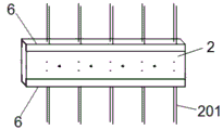
FIG. 2 is a schematic view of a node structure according to the present invention;
FIG. 3 is a schematic view of the installation of the lower precast shear wall member and the precast floor slab of the present invention;
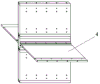
FIG. 4 is a schematic view of the assembly of the upper and lower precast shear wall members and the precast floor slab of the present invention;
FIG. 5 is a sectional view taken along line A of FIG. 4 in accordance with the present invention;
FIG. 6 is a schematic view of the complete structure of the present invention after pouring laminated floor slabs;
the prefabricated shear wall comprises a prefabricated shear wall component 1, a prefabricated shear wall component 101, grouting holes 102, exhaust holes 103, anchoring rib preformed holes 2, a node component 201, preformed anchoring ribs 3, prefabricated floor slabs 301, floor slab preformed ribs 4, laminated floor slabs 5, angle steels 6, end channel steels 7 and prestressed ribs.
Detailed Description
The present invention will be described in further detail with reference to the following examples:
the prefabricated shear wall component, the prefabricated floor slab and the node component can be processed in a factory, so that standardization and normalization of all components are ensured, the construction speed can be effectively saved, zero-humidity operation of a construction site is realized, industrial production and green construction are ensured, and the prefabricated shear wall component can be widely applied to an assembled shear wall structure.
As shown in fig. 1 to 6, the assembly-type shear wall transverse assembling device comprises a prefabricated shear wall member 1 in the vertical direction, a prefabricated floor slab 3 in the horizontal direction, and a connecting member for fixedly connecting the prefabricated shear wall member 1 and the prefabricated floor slab 3. The connecting component comprises a node component 2 fixedly connecting the upper prefabricated shear wall component 1 and the lower prefabricated shear wall component 1 and angle steel 5 arranged on two sides of the node component 2 and used for supporting and fixing the prefabricated floor slab 3. The angle steel 5 on one side of the node component 2 is symmetrically arranged into two parts along the upper side and the lower side of the prefabricated floor slab 3, the lower layer of angle steel 5 plays a role in supporting the prefabricated floor slab 3, and the upper layer of angle steel 5 plays a role in fixedly connecting the prefabricated floor slab 3. The angle steel 5 is fixedly connected with the node member 2 and the prefabricated floor slab 3 through bolts respectively, and preformed holes through which bolts can pass are formed in the angle steel 5, the node member 2 and the prefabricated floor slab 3 respectively, so that the angle steel is convenient to process and connect on site. Both ends of the prefabricated shear wall component 1, the prefabricated floor slab 3 and the node component 2 are provided with end channel steel 6 with a protection effect.
The cross-section of prefabricated floor 3 is the setting of type i shape, including the installation department and the middle height of both sides reduce, evenly set up the portion of pouring of a plurality of floor reservation muscle 301 and pour and be provided with on the portion and make highly keep equal coincide floor 4 with the installation department. The prefabricated floor slab (3) is fixedly connected with the node component 2 through the prestressed tendons 7. The double connection of the angle steel 5 and the prestressed tendons 7 between the precast floor slab 3 and the node member 2 ensures the effective bonding of the precast floor slab 3 and the node member 2, and meanwhile, the connection of the prestressed tendons 7 ensures the effective transmission of the hogging moment at the slab end of the precast floor slab.
A transverse assembling method of an assembled shear wall comprises the following specific steps:
A. and (3) shear wall formwork support: and (3) building a shear wall steel reinforcement framework, welding the end channel steel 6 and the shear wall steel reinforcement framework, and then installing the prefabricated shear wall component 1 to complete the formwork erection of the shear wall.
B. Assembling a node component: inserting reserved anchoring ribs 201 at the lower end of the node member 2 into anchoring rib reserved holes 103 at the upper end of the cast-in-situ shear wall, grouting from the grouting holes 101 at the same time until the grouting holes 101 are discharged from the exhaust holes 102, sealing the grouting holes 101, and then welding end channel steel 6 connecting the node member 2 and the cast-in-situ shear wall.
C. Installing angle steel: and installing angle steel 5 at the lower end of the prefabricated floor slab 3 through bolts.
D. Installing a prefabricated floor slab: the prefabricated floor slab 3 is placed above the angle steel 5, tensioning and fixing are carried out through the prestressed tendons 7, then the angle steel 5 arranged above the prefabricated floor slab 3 is fixedly installed through bolts, and the angle steel 5 above and below the prefabricated floor slab 3 is fixed through the bolts.
E. Pouring a composite floor slab: and pouring the composite floor slab 4 in situ until the height of the composite floor slab is flush with the height of the installation part of the prefabricated floor slab 3.
F. Assembling an upper layer shear wall: after the pouring and maintenance are completed, the prefabricated shear wall component 1 is hoisted to a designated position and assembled with the node component 2, the reserved anchoring ribs 201 at the upper end of the node component 2 are inserted into the anchoring rib reserved holes 103 at the lower end of the prefabricated shear wall component 1, grouting is performed from the grouting holes 101 until the grouting holes 102 are exhausted, the grouting holes 101 can be closed, and then the end channel steel 6 connecting the node component 2 and the prefabricated shear wall component 1 is welded.
G. And repeating the steps B to F until the required number of layers is reached.
Claims (9)
1. The utility model provides a device is transversely assembled to assembled shear force wall which characterized in that: the prefabricated shear wall comprises prefabricated shear wall components (1) in the vertical direction, prefabricated floor slabs (3) in the horizontal direction and connecting components for fixedly connecting the prefabricated shear wall components (1) and the prefabricated floor slabs (3), wherein the connecting components comprise node components (2) fixedly connected with upper and lower prefabricated shear wall components (1) and angle steel (5) arranged on two sides of the node components (2) and used for supporting and fixing the prefabricated floor slabs (3).
2. The assembled shear wall transverse assembling device of claim 1, wherein: both ends of the prefabricated shear wall component (1), the prefabricated floor slab (3) and the node component (2) are provided with end channel steel (6) with a protection effect.
3. The assembled shear wall transverse assembling device of claim 2, wherein: node component (2) are along the even interval of length direction and set up a plurality of reservation anchor muscle (201) of indulging node component (2) and reserve anchor muscle (201) and wear out the both sides of node component (2) and form the end of reserving.
4. The assembled shear wall transverse assembling device of claim 3, wherein: and anchor rib preformed holes (103) through which the preformed ends can penetrate out are formed in the positions, corresponding to the preformed anchor ribs (201), of the upper end and the lower end of the prefabricated shear wall component (1).
5. The assembled shear wall transverse assembling device of claim 4, wherein: and a grouting hole (101) for grouting into the anchoring rib preformed hole (103) is formed in the position, corresponding to the anchoring rib preformed hole (103), on one side of the prefabricated shear wall component (1), and an exhaust hole (102) communicated with the anchoring rib preformed hole (103) is formed above the grouting hole (101).
6. The assembled shear wall transverse assembling device of claim 2, wherein: the angle steel (5) on one side of the node member (2) is symmetrically arranged into two parts along the upper side and the lower side of the prefabricated floor slab (3), and the angle steel (5) is fixedly connected with the node member (2) and the prefabricated floor slab (3) through bolts.
7. The assembled shear wall transverse assembling device of claim 6, wherein: the cross-section of prefabricated floor slab (3) is the setting of type Chinese character 'ao', including the installation department of both sides and middle high reduction, evenly set up the portion of pouring of a plurality of floor reservation muscle (301) and pour and be provided with in the portion and make highly keep level coincide floor slab (4) with the installation department.
8. The assembled shear wall transverse assembling device of claim 7, wherein:
the prefabricated floor slab (3) is fixedly connected with the node member (2) through a prestressed tendon (7).
9. An assembling method using the transverse assembling device for the precast shear wall of claim 1, characterized in that: the method comprises the following specific steps:
A. and (3) shear wall formwork support: building a shear wall steel reinforcement framework, welding the end channel steel (6) and the shear wall steel reinforcement framework, and then installing the prefabricated shear wall component (1) to complete the formwork erection of the shear wall;
B. assembling a node component: inserting reserved anchoring ribs (201) at the lower end of the node member (2) into anchoring rib reserved holes (103) at the upper end of the cast-in-situ shear wall, grouting from the grouting holes (101) until the grouting holes are discharged from the exhaust holes (102), and sealing the grouting holes (101), and then welding end channel steel (6) connected with the node member (2) and the cast-in-situ shear wall;
C. installing angle steel: installing angle steel (5) at the lower end of the prefabricated floor slab (3) through bolts;
D. installing a prefabricated floor slab: placing the precast floor slab (3) above the angle steel (5), performing tensioning and fixing through the prestressed tendons (7), then fixedly installing the angle steel (5) arranged above the precast floor slab (3) through bolts, and fixing the angle steel (5) above and below the precast floor slab (3) through the bolts;
E. pouring a composite floor slab: pouring the composite floor slab (4) in situ until the height is flush with the height of the installation part of the prefabricated floor slab (3);
F. assembling an upper layer shear wall: after the pouring maintenance is finished, hoisting the prefabricated shear wall component (1) to a specified position to be assembled with the node component (2), inserting a reserved anchoring rib (201) at the upper end of the node component (2) into a reserved anchoring rib hole (103) at the lower end of the prefabricated shear wall component (1), grouting from a grouting hole (101) until the reserved anchoring rib is discharged from an exhaust hole (102), sealing the grouting hole (101), and then welding an end channel steel (6) connecting the node component (2) and the prefabricated shear wall component (1);
G. and repeating the steps B to F until the required number of layers is reached.
Priority Applications (1)
| Application Number | Priority Date | Filing Date | Title |
|---|---|---|---|
| CN201911101394.9A CN110792164B (en) | 2019-11-12 | 2019-11-12 | Transverse assembling device and method for assembled shear wall |
Applications Claiming Priority (1)
| Application Number | Priority Date | Filing Date | Title |
|---|---|---|---|
| CN201911101394.9A CN110792164B (en) | 2019-11-12 | 2019-11-12 | Transverse assembling device and method for assembled shear wall |
Publications (2)
| Publication Number | Publication Date |
|---|---|
| CN110792164A true CN110792164A (en) | 2020-02-14 |
| CN110792164B CN110792164B (en) | 2021-03-12 |
Family
ID=69444105
Family Applications (1)
| Application Number | Title | Priority Date | Filing Date |
|---|---|---|---|
| CN201911101394.9A Active CN110792164B (en) | 2019-11-12 | 2019-11-12 | Transverse assembling device and method for assembled shear wall |
Country Status (1)
| Country | Link |
|---|---|
| CN (1) | CN110792164B (en) |
Cited By (5)
| Publication number | Priority date | Publication date | Assignee | Title |
|---|---|---|---|---|
| CN112459281A (en) * | 2020-11-11 | 2021-03-09 | 杨玮军 | Steel sheet shear force wall quick positioning connection structure among assembly type structure |
| CN112627391A (en) * | 2020-12-16 | 2021-04-09 | 河海大学 | Construction process of prefabricated double-steel-plate-concrete combined shear wall |
| CN112922359A (en) * | 2021-04-12 | 2021-06-08 | 山东千悦建筑科技有限公司 | Prefabricated superposed shear wall mounting system and mounting method |
| CN113775064A (en) * | 2021-10-11 | 2021-12-10 | 和能人居科技(天津)集团股份有限公司 | Vibration reduction connecting structure of box plate type building, box plate type steel structure building and construction method of box plate type steel structure building |
| CN117386022A (en) * | 2023-11-28 | 2024-01-12 | 杭州嘉图建筑节能科技有限公司 | Assembled wall and floor slab connecting structure and construction method |
Citations (11)
| Publication number | Priority date | Publication date | Assignee | Title |
|---|---|---|---|---|
| CN1912294A (en) * | 2006-08-22 | 2007-02-14 | 邱则有 | Laminated inverted T-shaped board |
| CN101503887A (en) * | 2009-02-04 | 2009-08-12 | 南通建筑工程总承包有限公司 | Interlayer connection node between inner shear wall, plate and shear walls |
| KR20100120586A (en) * | 2009-05-06 | 2010-11-16 | 동국대학교 산학협력단 | Pc slab-wall connection structure and construction method thereof |
| CN106869330A (en) * | 2017-01-18 | 2017-06-20 | 黄坤坤 | A kind of assembled ring muscle is fastened and is anchored concrete shear force wall bilateral floor connection structure |
| CN206752741U (en) * | 2017-05-10 | 2017-12-15 | 郑俊煌 | A kind of vertical connecting node of prefabricated assembled shear wall |
| WO2017217863A1 (en) * | 2016-06-14 | 2017-12-21 | Polybo As | A building structure connecting means and a method of using same |
| CN207003723U (en) * | 2017-07-17 | 2018-02-13 | 广东省建科建筑设计院有限公司 | High-rise assembled single row of holes precast shear wall and its assembling structure |
| CN107882171A (en) * | 2017-11-21 | 2018-04-06 | 沈阳建筑大学 | One kind wears muscle assembly concrete-filled steel tube H-shaped steel beam joint system |
| CN207739402U (en) * | 2017-12-22 | 2018-08-17 | 广州市芳村建筑工程有限公司 | Assembly concrete connection structure |
| CN208329198U (en) * | 2018-03-23 | 2019-01-04 | 青岛腾远设计事务所有限公司 | A kind of dry connecting device for fabricated shear wall |
| CN209194695U (en) * | 2018-10-25 | 2019-08-02 | 江苏工程职业技术学院 | A kind of post-stressed overlapping balcony construct |
-
2019
- 2019-11-12 CN CN201911101394.9A patent/CN110792164B/en active Active
Patent Citations (11)
| Publication number | Priority date | Publication date | Assignee | Title |
|---|---|---|---|---|
| CN1912294A (en) * | 2006-08-22 | 2007-02-14 | 邱则有 | Laminated inverted T-shaped board |
| CN101503887A (en) * | 2009-02-04 | 2009-08-12 | 南通建筑工程总承包有限公司 | Interlayer connection node between inner shear wall, plate and shear walls |
| KR20100120586A (en) * | 2009-05-06 | 2010-11-16 | 동국대학교 산학협력단 | Pc slab-wall connection structure and construction method thereof |
| WO2017217863A1 (en) * | 2016-06-14 | 2017-12-21 | Polybo As | A building structure connecting means and a method of using same |
| CN106869330A (en) * | 2017-01-18 | 2017-06-20 | 黄坤坤 | A kind of assembled ring muscle is fastened and is anchored concrete shear force wall bilateral floor connection structure |
| CN206752741U (en) * | 2017-05-10 | 2017-12-15 | 郑俊煌 | A kind of vertical connecting node of prefabricated assembled shear wall |
| CN207003723U (en) * | 2017-07-17 | 2018-02-13 | 广东省建科建筑设计院有限公司 | High-rise assembled single row of holes precast shear wall and its assembling structure |
| CN107882171A (en) * | 2017-11-21 | 2018-04-06 | 沈阳建筑大学 | One kind wears muscle assembly concrete-filled steel tube H-shaped steel beam joint system |
| CN207739402U (en) * | 2017-12-22 | 2018-08-17 | 广州市芳村建筑工程有限公司 | Assembly concrete connection structure |
| CN208329198U (en) * | 2018-03-23 | 2019-01-04 | 青岛腾远设计事务所有限公司 | A kind of dry connecting device for fabricated shear wall |
| CN209194695U (en) * | 2018-10-25 | 2019-08-02 | 江苏工程职业技术学院 | A kind of post-stressed overlapping balcony construct |
Cited By (6)
| Publication number | Priority date | Publication date | Assignee | Title |
|---|---|---|---|---|
| CN112459281A (en) * | 2020-11-11 | 2021-03-09 | 杨玮军 | Steel sheet shear force wall quick positioning connection structure among assembly type structure |
| CN112627391A (en) * | 2020-12-16 | 2021-04-09 | 河海大学 | Construction process of prefabricated double-steel-plate-concrete combined shear wall |
| CN112922359A (en) * | 2021-04-12 | 2021-06-08 | 山东千悦建筑科技有限公司 | Prefabricated superposed shear wall mounting system and mounting method |
| CN113775064A (en) * | 2021-10-11 | 2021-12-10 | 和能人居科技(天津)集团股份有限公司 | Vibration reduction connecting structure of box plate type building, box plate type steel structure building and construction method of box plate type steel structure building |
| CN117386022A (en) * | 2023-11-28 | 2024-01-12 | 杭州嘉图建筑节能科技有限公司 | Assembled wall and floor slab connecting structure and construction method |
| CN117386022B (en) * | 2023-11-28 | 2024-06-11 | 杭州嘉图建筑节能科技有限公司 | Assembled wall and floor slab connecting structure and construction method |
Also Published As
| Publication number | Publication date |
|---|---|
| CN110792164B (en) | 2021-03-12 |
Similar Documents
| Publication | Publication Date | Title |
|---|---|---|
| CN110792164B (en) | Transverse assembling device and method for assembled shear wall | |
| CN102808465B (en) | Assembly connecting structure and assembly connecting method of assembled concrete frame and shear wall combination | |
| CN202831296U (en) | Assembled spliced connecting structure of concrete frame-shear wall and structure constructed | |
| CN107905424B (en) | Full-prefabricated one-way plate structure with splicing grooves, manufacturing and assembling methods | |
| CN109653350B (en) | Mixed reinforcement embedded low-prestress dry beam column node and method | |
| CN108301545A (en) | A kind of big module overlapping contignation of the assembled with space truss temporary support | |
| CN110700873A (en) | Prefabricated rail top air duct for subway station and construction method thereof | |
| CN114319977B (en) | Steel pipe concrete row column type connection precast shear wall structure and construction method | |
| CN210887565U (en) | Assembled bolted connection roof beam-post node | |
| CN109667376B (en) | Novel superposed floor system suitable for H-shaped steel beam of steel structure and construction method thereof | |
| CN113502835A (en) | Wet cellular assembled gridwork roof beam slope protection structure of connecting | |
| CN206769199U (en) | After wear formula post stretching vertical prestressing cast-in-place concrete rod structure | |
| CN211312950U (en) | Assembled integral elevator shaft prefabricated part | |
| CN111719693A (en) | Prestress assembly type steel-concrete sleeved beam-column joint | |
| CN204781443U (en) | Device for connecting precast shear wall concatenation about being used for | |
| CN208039577U (en) | Half prefabricated prestressed concrete floor slab of figure of eight steel bar girder | |
| CN110872813A (en) | Precast concrete guardrail connecting structure and assembling method | |
| CN213174518U (en) | Connecting structure for connecting parts on prefabricated stairs | |
| CN210919128U (en) | Prefabricated rail top air duct for subway station | |
| CN211286164U (en) | Self-compaction regeneration block concrete superimposed shear wall | |
| CN113445652A (en) | Plate end slotted hole SP hollow composite slab-steel beam connecting structure and construction method thereof | |
| CN206769198U (en) | Separate combination type armored concrete prefabricated section anchored end supporting construction | |
| CN217175198U (en) | Connecting structure of steel bar truss floor bearing plate and reinforced concrete wall | |
| CN220335680U (en) | Combined beam bridge | |
| CN211596396U (en) | Precast concrete guardrail connection structure |
Legal Events
| Date | Code | Title | Description |
|---|---|---|---|
| PB01 | Publication | ||
| PB01 | Publication | ||
| SE01 | Entry into force of request for substantive examination | ||
| SE01 | Entry into force of request for substantive examination | ||
| GR01 | Patent grant | ||
| GR01 | Patent grant |