CN110746891A - Oversized hot melt adhesive laminating process - Google Patents
Oversized hot melt adhesive laminating process Download PDFInfo
- Publication number
- CN110746891A CN110746891A CN201911081730.8A CN201911081730A CN110746891A CN 110746891 A CN110746891 A CN 110746891A CN 201911081730 A CN201911081730 A CN 201911081730A CN 110746891 A CN110746891 A CN 110746891A
- Authority
- CN
- China
- Prior art keywords
- box body
- ash removal
- removal device
- melt adhesive
- hot melt
- Prior art date
- Legal status (The legal status is an assumption and is not a legal conclusion. Google has not performed a legal analysis and makes no representation as to the accuracy of the status listed.)
- Withdrawn
Links
- 238000000034 method Methods 0.000 title claims abstract description 24
- 239000004831 Hot glue Substances 0.000 title claims abstract description 23
- 238000010030 laminating Methods 0.000 title claims abstract description 10
- 239000000428 dust Substances 0.000 claims abstract description 27
- 238000004140 cleaning Methods 0.000 claims abstract description 17
- 230000005540 biological transmission Effects 0.000 claims abstract description 15
- 238000004026 adhesive bonding Methods 0.000 claims abstract description 13
- 239000003292 glue Substances 0.000 claims description 21
- 238000007689 inspection Methods 0.000 claims description 12
- 239000000463 material Substances 0.000 claims description 9
- 238000007731 hot pressing Methods 0.000 claims description 6
- 230000003749 cleanliness Effects 0.000 claims description 3
- 239000011248 coating agent Substances 0.000 claims description 3
- 238000000576 coating method Methods 0.000 claims description 3
- 239000004744 fabric Substances 0.000 claims description 3
- 238000005286 illumination Methods 0.000 claims description 3
- 230000005389 magnetism Effects 0.000 claims description 3
- 239000002245 particle Substances 0.000 claims description 3
- 239000002904 solvent Substances 0.000 claims description 3
- 241000252254 Catostomidae Species 0.000 claims 2
- 230000006978 adaptation Effects 0.000 claims 1
- 239000012535 impurity Substances 0.000 abstract description 11
- 238000003475 lamination Methods 0.000 description 3
- 230000000694 effects Effects 0.000 description 2
- 230000009286 beneficial effect Effects 0.000 description 1
- 230000007547 defect Effects 0.000 description 1
- 239000004973 liquid crystal related substance Substances 0.000 description 1
- 238000004519 manufacturing process Methods 0.000 description 1
- 238000012986 modification Methods 0.000 description 1
- 230000004048 modification Effects 0.000 description 1
- 230000007306 turnover Effects 0.000 description 1
Images


Classifications
-
- C—CHEMISTRY; METALLURGY
- C09—DYES; PAINTS; POLISHES; NATURAL RESINS; ADHESIVES; COMPOSITIONS NOT OTHERWISE PROVIDED FOR; APPLICATIONS OF MATERIALS NOT OTHERWISE PROVIDED FOR
- C09J—ADHESIVES; NON-MECHANICAL ASPECTS OF ADHESIVE PROCESSES IN GENERAL; ADHESIVE PROCESSES NOT PROVIDED FOR ELSEWHERE; USE OF MATERIALS AS ADHESIVES
- C09J5/00—Adhesive processes in general; Adhesive processes not provided for elsewhere, e.g. relating to primers
- C09J5/02—Adhesive processes in general; Adhesive processes not provided for elsewhere, e.g. relating to primers involving pretreatment of the surfaces to be joined
-
- B—PERFORMING OPERATIONS; TRANSPORTING
- B08—CLEANING
- B08B—CLEANING IN GENERAL; PREVENTION OF FOULING IN GENERAL
- B08B1/00—Cleaning by methods involving the use of tools
- B08B1/10—Cleaning by methods involving the use of tools characterised by the type of cleaning tool
- B08B1/14—Wipes; Absorbent members, e.g. swabs or sponges
- B08B1/143—Wipes
-
- B—PERFORMING OPERATIONS; TRANSPORTING
- B08—CLEANING
- B08B—CLEANING IN GENERAL; PREVENTION OF FOULING IN GENERAL
- B08B1/00—Cleaning by methods involving the use of tools
- B08B1/30—Cleaning by methods involving the use of tools by movement of cleaning members over a surface
- B08B1/32—Cleaning by methods involving the use of tools by movement of cleaning members over a surface using rotary cleaning members
-
- B—PERFORMING OPERATIONS; TRANSPORTING
- B08—CLEANING
- B08B—CLEANING IN GENERAL; PREVENTION OF FOULING IN GENERAL
- B08B15/00—Preventing escape of dirt or fumes from the area where they are produced; Collecting or removing dirt or fumes from that area
- B08B15/04—Preventing escape of dirt or fumes from the area where they are produced; Collecting or removing dirt or fumes from that area from a small area, e.g. a tool
-
- C—CHEMISTRY; METALLURGY
- C09—DYES; PAINTS; POLISHES; NATURAL RESINS; ADHESIVES; COMPOSITIONS NOT OTHERWISE PROVIDED FOR; APPLICATIONS OF MATERIALS NOT OTHERWISE PROVIDED FOR
- C09J—ADHESIVES; NON-MECHANICAL ASPECTS OF ADHESIVE PROCESSES IN GENERAL; ADHESIVE PROCESSES NOT PROVIDED FOR ELSEWHERE; USE OF MATERIALS AS ADHESIVES
- C09J5/00—Adhesive processes in general; Adhesive processes not provided for elsewhere, e.g. relating to primers
- C09J5/06—Adhesive processes in general; Adhesive processes not provided for elsewhere, e.g. relating to primers involving heating of the applied adhesive
Landscapes
- Chemical & Material Sciences (AREA)
- Organic Chemistry (AREA)
- Cleaning In General (AREA)
Abstract
The invention discloses a gluing process of an oversized hot melt adhesive, which relates to the relevant technical field of gluing and comprises five steps. The invention also discloses ash removal equipment for the oversized hot melt adhesive laminating process, which comprises a box body and a bottom plate fixedly arranged at the bottom side of the box body, wherein a fixing plate is arranged at an opening at the top side of the box body, a sucking disc is arranged at the bottom side of the fixing plate, and the fixing plate is connected with a workpiece through the sucking disc on the fixing plate. The dust collector can fully clean the cleaning surface of a workpiece, in addition, the removed dust and impurities are sucked into the dust collection hopper through the operation of the suction fan and then are transmitted into the collection box through the transmission pipe, so that the dust and impurities can be collected in a centralized manner, the dust and impurities in the box can be cleaned regularly by turning over the collection box, and the mounting and dismounting between the fixed plate and the box body are facilitated through the matching use among the movable rod, the clamping head, the spring and the clamping groove, so that the workpiece to be processed can be conveniently placed in and the processed workpiece can be conveniently taken out.
Description
Technical Field
The invention relates to the technical field of lamination, in particular to a lamination process of an oversized hot melt adhesive.
Background
During production operation of a large-size liquid crystal panel industry, a laminating process needs to be carried out, two fixed or fixed panel workpieces are adhered to each other through a hot melt adhesive, the workpieces need to be cleaned before lamination, the laminating effect is prevented from being influenced by dust impurities on the adhesion surfaces of the workpieces, however, the ash removal operation is usually carried out manually in the existing process, the labor intensity is increased, the manual cleaning time is long, the working efficiency is low, and the cleaned dust impurities cannot be collected and processed in a centralized mode.
Therefore, it is necessary to provide an oversized hot melt adhesive application process to solve the above problems.
Disclosure of Invention
Technical problem to be solved
Aiming at the defects of the prior art, the invention provides an oversized hot melt adhesive laminating process, which solves the problems in the background art.
(II) technical scheme
In order to achieve the purpose, the invention is realized by the following technical scheme:
a gluing process of an oversized hot melt adhesive comprises the following steps:
a: arranging a first panel and a second panel, and carrying out material inspection on the first panel and the second panel in an environment with illumination of 900-;
b: cleaning the joint surfaces of the two panels by using a deashing device, wherein the working environment temperature is 20-36 ℃, and the concentration of floating dust particles in the air is less than 15mg/m3The cleanliness of the ash removing equipment is synchronously ensured, and the secondary pollution of products is prevented;
c: sucking materials by using a mechanical arm, moving a panel to a station of glue extruding equipment, adjusting the angle of the panel after sucking the materials, fixing the panel arranged on a tool module by using a fixing clamp with magnetism on an automatic clamping station, extruding glue by using the extruding equipment, controlling the temperature to be 86-89 ℃, and thermally coating and smearing the bonding glue on a bonding surface of the panel;
d: attaching and carrying out hot-pressing treatment on the first panel and the second panel coated with the glue, and then carrying out defoaming treatment, wherein the hot pressing and the defoaming are carried out in a vacuum environment, the working temperature is higher than 42 ℃, and then cleaning is carried out by using dust-free cloth to be dipped in a solvent, so that residual glue and overflowing glue overflowing out of the edge of the product are cleaned;
e: and (3) putting the product into a UV furnace for ultraviolet irradiation to cure the product, wherein the curing temperature is higher than 62 ℃, and after the product glue is cured, finally carrying out secondary inspection on the product, wherein the inspection requirement is to inspect according to the inspection standard provided by a customer to ensure that the product is qualified.
An ash cleaning device for an oversized hot melt adhesive laminating process comprises a box body and a bottom plate fixedly arranged at the bottom side of the box body, a fixing plate is arranged at the top opening of the box body, a sucking disc is arranged at the bottom side of the fixing plate, and the fixed plate is connected with a workpiece through a sucker on the fixed plate, guide rods are fixedly connected with the front side and the rear side of the upper part in the box body, the number of the guide rods is two, a screw rod is arranged between the two guide rods in parallel, a movable seat is arranged on the guide rods in a sliding way, a dust suction hopper is fixedly arranged at the bottom side in the box body, a suction fan is fixedly arranged at the left end of the inner bottom wall of the box body, a collecting box is arranged at the bottom end of the left side outside the box body, a second transmission pipe is arranged between the collection box and the suction fan, supporting plates are arranged on the front side and the rear side of the collection box, and the top of the supporting plate is rotatably provided with a rotating shaft, and the rotating shaft of the supporting plate on the front side of the collecting box is fixedly connected with a rocking handle.
Optionally, two sides of the opening at the top side of the box body are fixedly connected with fixing blocks;
the screw rod is rotatably connected with the box body.
Optionally, a threaded hole is formed in the middle of the bottom end of the movable seat, perforations matched with the guide rod are formed in the front side and the rear side of the bottom end of the movable seat, and the movable seat is in threaded connection with the lead screw through the threaded hole.
Optionally, a motor is fixedly installed at the right end of the bottom plate;
the right end of the screw rod penetrates through the box body and is connected with the output end of the motor through belt wheel transmission.
Optionally, a first transmission pipe is fixedly connected between the dust suction hopper and the suction fan;
the second transmission pipe is connected with the collecting box through a rotary joint.
Optionally, the second conveying pipe penetrates through the left side wall of the box body;
the top side of the collecting box is provided with a cover plate.
Optionally, the rotating shaft is fixedly connected with the collecting box;
the supporting plate is fixedly arranged on the bottom plate.
Optionally, a bolt is inserted into the rocking handle, and the inner end of the bolt penetrates through the supporting plate and is connected with the collecting box.
Optionally, an access door is installed on the front face of the box body, and a cleaning roller is movably installed at the top end of the movable seat.
(III) advantageous effects
The invention provides an oversized hot melt adhesive laminating process, which has the following beneficial effects:
(1) the motor drives the screw rod to rotate forwards and backwards, so that the cleaning roller moves left and right, the cleaning surface of the workpiece can be sufficiently cleaned, in addition, the cleaned dust and impurities are sucked into the dust suction hopper through the work of the suction fan and then are transmitted into the collecting box through the transmission pipe, so that the dust and impurities can be intensively collected, and the dust and impurities in the box can be regularly cleaned through overturning the collecting box, so that the cleaning machine is convenient to use.
(2) The movable rod, the clamping head, the spring and the clamping groove are matched for use, so that the fixed plate and the box body are convenient to mount and dismount, workpieces to be processed can be conveniently placed in and taken out at a later stage, the workpieces are adsorbed by the sucking disc at the bottom side of the fixed plate, and the workpieces are convenient to mount.
Drawings
FIG. 1 is a schematic view of the external structure of the ash removal device of the present invention;
FIG. 2 is a schematic cross-sectional view of the ash removal device of the present invention;
FIG. 3 is an enlarged cross-sectional view taken at A in FIG. 1 in accordance with the present invention;
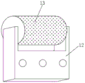
FIG. 4 is a schematic view of a movable seat of the present invention;
FIG. 5 is a side view of the supporting plate of the present invention.
In the figure: the device comprises a box body 1, a bottom plate 2, a fixing plate 3, a fixing block 4, a movable rod 5, a clamping head 6, a spring 7, a clamping groove 8, a workpiece 9, a screw rod 10, a guide rod 11, a movable seat 12, a cleaning roller 13, a motor 14, a dust collection hopper 15, a suction fan 16, a first transmission pipe 17, a second transmission pipe 18, a collection box 19, a support plate 20, a rotating shaft 21, a rocking handle 22, a cover plate 23 and an access door 24.
Detailed Description
The technical solutions in the embodiments of the present invention will be clearly and completely described below with reference to the drawings in the embodiments of the present invention, and it is obvious that the described embodiments are only a part of the embodiments of the present invention, and not all of the embodiments. All other embodiments, which can be derived by a person skilled in the art from the embodiments given herein without making any creative effort, shall fall within the protection scope of the present invention.
In the description of the present invention, it is to be understood that the terms "central," "longitudinal," "lateral," "length," "width," "thickness," "upper," "lower," "front," "rear," "left," "right," "vertical," "horizontal," "top," "bottom," "inner," "outer," "clockwise," "counterclockwise," "axial," "radial," "circumferential," and the like are used in the orientations and positional relationships indicated in the drawings for convenience in describing the invention and to simplify the description, and are not intended to indicate or imply that the referenced device or element must have a particular orientation, be constructed and operated in a particular orientation, and are not to be considered limiting of the invention.
In the present invention, unless otherwise expressly specified or limited, the terms "disposed," "mounted," "connected," and "fixed" are to be construed broadly and may, for example, be fixedly connected or detachably connected; may be a mechanical connection; may be directly connected or indirectly connected through an intermediate. The specific meanings of the above terms in the present invention can be understood by those skilled in the art according to specific situations.
Furthermore, the terms "first", "second", etc. are used for descriptive purposes only and are not to be construed as indicating or implying relative importance or implicitly indicating the number of technical features indicated. Thus, a feature defined as "first" or "second" may explicitly or implicitly include one or more of that feature.
The invention provides a technical scheme that:
a gluing process of an oversized hot melt adhesive comprises the following steps:
a: arranging a first panel and a second panel, and carrying out material inspection on the first panel and the second panel in an environment with illumination of 900-;
b: cleaning the joint surfaces of the two panels by using a deashing device, wherein the working environment temperature is 20-36 ℃, and the concentration of floating dust particles in the air is less than 15mg/m3The cleanliness of the ash removing equipment is synchronously ensured, and the secondary pollution of products is prevented;
c: sucking materials by using a mechanical arm, moving a panel to a station of glue extruding equipment, adjusting the angle of the panel after sucking the materials, fixing the panel arranged on a tool module by using a fixing clamp with magnetism on an automatic clamping station, extruding glue by using the extruding equipment, controlling the temperature to be 86-89 ℃, and thermally coating and smearing the bonding glue on a bonding surface of the panel;
d: attaching and carrying out hot-pressing treatment on the first panel and the second panel coated with the glue, and then carrying out defoaming treatment, wherein the hot pressing and the defoaming are carried out in a vacuum environment, the working temperature is higher than 42 ℃, and then cleaning is carried out by using dust-free cloth to be dipped in a solvent, so that residual glue and overflowing glue overflowing out of the edge of the product are cleaned;
e: and (3) putting the product into a UV furnace for ultraviolet irradiation to cure the product, wherein the curing temperature is higher than 62 ℃, and after the product glue is cured, finally carrying out secondary inspection on the product, wherein the inspection requirement is to inspect according to the inspection standard provided by a customer to ensure that the product is qualified.
As shown in fig. 1-5, an ash removing device for an oversized hot melt adhesive laminating process comprises a box body 1 and a bottom plate 2 fixedly installed at the bottom side of the box body 1, a fixed plate 3 is installed at an opening at the top side of the box body 1, fixed blocks 4 are fixedly connected to both sides of the opening at the top side of the box body 1, a spring 7 is fixedly installed in a cavity of each fixed block 4, a movable rod 5 is inserted into the spring 7, a chuck 6 is fixedly connected to the end of the movable rod 5, the chuck 6 is slidably installed in the fixed block 4, a clamping groove 8 matched with the chuck 6 is formed in the fixed plate 3, the chuck 6 is clamped with the clamping groove 8, the movable rod 5, the chuck 6, the spring 7 and the clamping groove 8 are matched for use, the movable rod 5 is pulled outwards to enable the chuck 6 to compress the spring 7, meanwhile, the connection between the chuck 6 and the clamping, on the contrary, the chuck 6 is clamped with the clamping groove 8 under the reverse acting force of the spring 7, so that the fixing plate 3 is conveniently installed on the box body 1, the bottom side of the fixing plate 3 is provided with a sucker, the fixing plate 3 is connected with a workpiece 9 through the sucker on the fixing plate, the front side and the rear side of the upper part in the box body 1 are fixedly connected with guide rods 11, the two guide rods 11 are arranged in two, a lead screw 10 is arranged between the two guide rods 11 in parallel, the lead screw 10 is rotatably connected with the box body 1, a movable seat 12 is slidably installed on the guide rods 11, the middle part of the bottom end of the movable seat 12 is provided with a threaded hole, the front side and the rear side of the bottom end of the movable seat 12 are respectively provided with a through hole matched with the guide rods 11, the movable seat 12 is in threaded connection with the lead screw 10 through the threaded hole, the top end of the movable seat 12 is movably provided with, the screw rod 10 is driven by a motor 14 to rotate positively and negatively, the screw rod 10 drives a movable seat 12 to slide left and right along a guide rod 11, so that a cleaning surface of a workpiece 9 is cleaned by a cleaning roller 13, a dust suction hopper 15 is fixedly arranged at the bottom side inside the box body 1, a suction fan 16 is fixedly arranged at the left end of the inner bottom wall of the box body 1, a first transmission pipe 17 is fixedly connected between the dust suction hopper 15 and the suction fan 16 and is used by matching the dust suction hopper 15 with the suction fan 16 for absorbing removed dust and impurities, a collection box 19 is arranged at the bottom end of the left side outside the box body 1 and is used for collecting the dust and impurities in a centralized manner, a second transmission pipe 18 is arranged between the collection box 19 and the suction fan 16, the second transmission pipe 18 is connected with the collection box 19 through a rotary joint, the second transmission pipe 18 penetrates through the left side wall of the box body 1, a cover plate 23, and the top of backup pad 20 rotates and installs pivot 21, pivot 21 and collecting box 19 fixed connection, backup pad 20 fixed mounting is on bottom plate 2, fixedly connected with rocking handle 22 on the pivot 21 of collecting box 19 front side backup pad 20, it has the bolt to peg graft on the rocking handle 22, the inner of bolt runs through backup pad 20 and is connected with collecting box 19, access door 24 is installed on the front of box 1, through opening access door 24, the staff of being convenient for maintains or maintains the incasement portion.
The working principle is as follows: when the dust collection box 19 needs to be cleaned, the connection between the second transmission pipe 18 and the collection box 19 is released through the rotary joint, the cover plate 23 is removed, the bolt is screwed off, the crank 22 is rotated to turn over the collection box 19, and meanwhile, pouring out the collected dust and impurities.
It is noted that in the present disclosure, unless otherwise explicitly specified or limited, a first feature "on" or "under" a second feature may be directly contacted with the first and second features, or indirectly contacted with the first and second features through intervening media. Also, a first feature "on," "over," and "above" a second feature may be directly or diagonally above the second feature, or may simply indicate that the first feature is at a higher level than the second feature. A first feature being "under," "below," and "beneath" a second feature may be directly under or obliquely under the first feature, or may simply mean that the first feature is at a lesser elevation than the second feature.
Finally, it should be noted that: although the present invention has been described in detail with reference to the foregoing embodiments, it will be apparent to those skilled in the art that modifications may be made to the embodiments or portions thereof without departing from the spirit and scope of the invention.
Claims (10)
1. The laminating process of the oversized hot melt adhesive is characterized by comprising the following steps of:
a: arranging a first panel and a second panel, and carrying out material inspection on the first panel and the second panel in an environment with illumination of 900-;
b: cleaning the joint surfaces of the two panels by using a deashing device, wherein the working environment temperature is 20-36 ℃, and the concentration of floating dust particles in the air is less than 15mg/m3The cleanliness of the ash removing equipment is synchronously ensured, and the secondary pollution of products is prevented;
c: sucking materials by using a mechanical arm, moving a panel to a station of glue extruding equipment, adjusting the angle of the panel after sucking the materials, fixing the panel arranged on a tool module by using a fixing clamp with magnetism on an automatic clamping station, extruding glue by using the extruding equipment, controlling the temperature to be 86-89 ℃, and thermally coating and smearing the bonding glue on a bonding surface of the panel;
d: attaching and carrying out hot-pressing treatment on the first panel and the second panel coated with the glue, and then carrying out defoaming treatment, wherein the hot pressing and the defoaming are carried out in a vacuum environment, the working temperature is higher than 42 ℃, and then cleaning is carried out by using dust-free cloth to be dipped in a solvent, so that residual glue and overflowing glue overflowing out of the edge of the product are cleaned;
e: and (3) putting the product into a UV furnace for ultraviolet irradiation to cure the product, wherein the curing temperature is higher than 62 ℃, and after the product glue is cured, finally carrying out secondary inspection on the product, wherein the inspection requirement is to inspect according to the inspection standard provided by a customer to ensure that the product is qualified.
2. The ash removal equipment for the oversized hot melt adhesive bonding process according to claim 1, comprising a box body (1) and a bottom plate (2) fixedly mounted at the bottom side of the box body (1), and is characterized in that:
the automatic dust collector is characterized in that a fixed plate (3) is installed at an opening in the top side of the box body (1), suckers are arranged on the bottom side of the fixed plate (3), the fixed plate (3) is connected with a workpiece (9) through the suckers on the fixed plate, guide rods (11) are fixedly connected to the front side and the rear side of the upper portion of the interior of the box body (1), the number of the guide rods (11) is two, a lead screw (10) is arranged between the two guide rods (11) in parallel, a movable seat (12) is slidably installed on the guide rods (11), a dust suction hopper (15) is fixedly installed on the bottom side of the interior of the box body (1), a suction fan (16) is fixedly installed at the left end of the inner bottom wall of the box body (1), a collecting box (19) is arranged at the bottom end of the left side of the exterior of the box body (1), and the top end of the supporting plate (20) is rotatably provided with a rotating shaft (21), and the rotating shaft (21) of the supporting plate (20) at the front side of the collecting box (19) is fixedly connected with a rocking handle (22).
3. The ash removal device for the oversized hot melt adhesive bonding process according to claim 2, wherein the ash removal device comprises:
both sides of an opening at the top side of the box body (1) are fixedly connected with fixing blocks (4);
the screw rod (10) is rotatably connected with the box body (1).
4. The ash removal device for the oversized hot melt adhesive bonding process according to claim 2, wherein the ash removal device comprises:
the bottom middle part of sliding seat (12) is provided with the screw hole, both sides all are provided with the perforation with guide arm (11) looks adaptation around the bottom of sliding seat (12), sliding seat (12) pass through screw hole and lead screw (10) threaded connection.
5. The ash removal device for the oversized hot melt adhesive bonding process according to claim 2, wherein the ash removal device comprises:
a motor (14) is fixedly arranged at the right end of the bottom plate (2);
the right end of the screw rod (10) penetrates through the box body (1) and is connected with the output end of the motor (14) through belt wheel transmission.
6. The ash removal device for the oversized hot melt adhesive bonding process according to claim 2, wherein the ash removal device comprises:
a first transmission pipe (17) is fixedly connected between the dust suction hopper (15) and the suction fan (16);
the second transfer pipe (18) is connected with the collection box (19) through a rotary joint.
7. The ash removal device for the oversized hot melt adhesive bonding process according to claim 2, wherein the ash removal device comprises:
the second conveying pipe (18) penetrates through the left side wall of the box body (1);
a cover plate (23) is arranged on the top side of the collecting box (19).
8. The ash removal device for the oversized hot melt adhesive bonding process according to claim 2, wherein the ash removal device comprises:
the rotating shaft (21) is fixedly connected with the collecting box (19);
the supporting plate (20) is fixedly arranged on the bottom plate (2).
9. The ash removal device for the oversized hot melt adhesive bonding process according to claim 2, wherein the ash removal device comprises:
the rocking handle (22) is inserted with a bolt, and the inner end of the bolt penetrates through the supporting plate (20) and is connected with the collecting box (19).
10. The ash removal device for the oversized hot melt adhesive bonding process according to claim 2, wherein the ash removal device comprises:
an access door (24) is installed on the front face of the box body (1), and a cleaning roller (13) is movably installed at the top end of the movable seat (12).
Priority Applications (1)
| Application Number | Priority Date | Filing Date | Title |
|---|---|---|---|
| CN201911081730.8A CN110746891A (en) | 2019-11-07 | 2019-11-07 | Oversized hot melt adhesive laminating process |
Applications Claiming Priority (1)
| Application Number | Priority Date | Filing Date | Title |
|---|---|---|---|
| CN201911081730.8A CN110746891A (en) | 2019-11-07 | 2019-11-07 | Oversized hot melt adhesive laminating process |
Publications (1)
| Publication Number | Publication Date |
|---|---|
| CN110746891A true CN110746891A (en) | 2020-02-04 |
Family
ID=69282557
Family Applications (1)
| Application Number | Title | Priority Date | Filing Date |
|---|---|---|---|
| CN201911081730.8A Withdrawn CN110746891A (en) | 2019-11-07 | 2019-11-07 | Oversized hot melt adhesive laminating process |
Country Status (1)
| Country | Link |
|---|---|
| CN (1) | CN110746891A (en) |
Cited By (4)
| Publication number | Priority date | Publication date | Assignee | Title |
|---|---|---|---|---|
| CN111940351A (en) * | 2020-09-01 | 2020-11-17 | 晋中学院 | 3D printing apparatus metal powder cleaning device |
| CN112357737A (en) * | 2020-10-30 | 2021-02-12 | 杭州西奥电梯有限公司 | Dust removal escalator |
| CN113275351A (en) * | 2021-05-21 | 2021-08-20 | 机械工业第九设计研究院有限公司 | Weld cigarette dust collector that welds between loading |
| CN114011674A (en) * | 2021-11-09 | 2022-02-08 | 常州百佳年代薄膜科技股份有限公司 | Preparation process of weather-resistant reflective film for warning board |
-
2019
- 2019-11-07 CN CN201911081730.8A patent/CN110746891A/en not_active Withdrawn
Cited By (5)
| Publication number | Priority date | Publication date | Assignee | Title |
|---|---|---|---|---|
| CN111940351A (en) * | 2020-09-01 | 2020-11-17 | 晋中学院 | 3D printing apparatus metal powder cleaning device |
| CN112357737A (en) * | 2020-10-30 | 2021-02-12 | 杭州西奥电梯有限公司 | Dust removal escalator |
| CN112357737B (en) * | 2020-10-30 | 2023-11-10 | 杭州西奥电梯有限公司 | Dust removal staircase |
| CN113275351A (en) * | 2021-05-21 | 2021-08-20 | 机械工业第九设计研究院有限公司 | Weld cigarette dust collector that welds between loading |
| CN114011674A (en) * | 2021-11-09 | 2022-02-08 | 常州百佳年代薄膜科技股份有限公司 | Preparation process of weather-resistant reflective film for warning board |
Similar Documents
| Publication | Publication Date | Title |
|---|---|---|
| CN110746891A (en) | Oversized hot melt adhesive laminating process | |
| CN112845475B (en) | Two-sided cleaning equipment of glass board | |
| WO2021120321A1 (en) | Automatic film sticking machine | |
| CN116423244B (en) | Shell cutting device for processing sheet metal cabinet body and use method | |
| CN110026829B (en) | Surface finish device of new building material production usefulness | |
| CN114613690B (en) | Semiconductor thickness detection and comparison device | |
| CN117961706A (en) | Forming equipment for PVC pipeline processing and manufacturing | |
| CN213616471U (en) | Waste ammeter circuit board nail loosening device | |
| CN211303579U (en) | Quick drying's diamond saw blade spraying equipment | |
| CN219817439U (en) | Dismounting device for crystalline silicon photovoltaic module | |
| CN114802898B (en) | Automatic film sticking machine for socket | |
| CN209435572U (en) | One kind being used for LED circuit board SMT chip mounter | |
| CN216066780U (en) | Device for deburring cut plate | |
| CN115394625A (en) | Equipment and process method for maintaining spare parts of LCD (liquid crystal display) dry plasma etching equipment | |
| CN112936678A (en) | Curing oven for solar module | |
| CN210173258U (en) | Polishing equipment for machining precision products | |
| CN206123367U (en) | Quartz stone plate polisher | |
| CN221435367U (en) | Automatic clamping structure for laser cutting machine | |
| CN217993846U (en) | Multi-station battery code spraying and transfer printing equipment | |
| CN111009480B (en) | Carbon dioxide dry method automatic cleaning machine for electronic semiconductor | |
| CN220180192U (en) | Tectorial membrane host computer area removes powder structure | |
| CN217594153U (en) | Automatic cleaning device for filter cartridge | |
| CN218018067U (en) | Vacuum adsorption clamp for prism processing | |
| CN214025072U (en) | Polishing device convenient for ash removal for metal product processing | |
| CN213503095U (en) | Surface coating equipment with conveying structure for electrolytic copper packaging |
Legal Events
| Date | Code | Title | Description |
|---|---|---|---|
| PB01 | Publication | ||
| PB01 | Publication | ||
| SE01 | Entry into force of request for substantive examination | ||
| SE01 | Entry into force of request for substantive examination | ||
| WW01 | Invention patent application withdrawn after publication | ||
| WW01 | Invention patent application withdrawn after publication |
Application publication date: 20200204 |