Disclosure of Invention
The invention aims to provide a rubber tube cutting and feeding device which is accurate in rubber tube sleeving action, controllable in rubber tube fixed length, capable of detecting material breakage and capable of straightening electronic element terminals, aiming at the defects in the prior art.
For the purpose of the invention, the following technical scheme is adopted for realizing the purpose: a rubber tube cutting and feeding device comprises a rubber tube coiling and feeding assembly and a rubber tube sleeving assembly, wherein the rubber tube coiling and feeding assembly is used for placing coiled rubber tubes and slowly feeding the rubber tubes; the rubber tube sleeving component is used for cutting, clamping and sleeving rubber tubes;
the rubber tube sleeving component comprises a mounting side plate, a driving motor, a driving gear, a driving rack, a transverse moving plate, a clamping cylinder, a clamping block, a material passing seat, a material pressing block, a material breaking detector, a shearing cylinder, a shearing knife and a material passing groove plate; the mounting side plate is fixedly arranged on the rack, the driving motor is fixedly arranged on the mounting side plate, the driving gear is arranged at the output end of the driving motor, and the driving gear is meshed with the driving rack; the transverse moving plate is movably matched on the mounting side plate through a sliding rail assembly, and the driving rack is mounted on the transverse moving plate; the clamping cylinder is arranged at the end part of the transverse moving plate, and the clamping blocks are fixedly arranged at two telescopic ends of the clamping cylinder; the material passing seat is fixed on the side of the mounting side plate, a round hole for the rubber tube to pass through is formed in the material passing seat, and a groove is formed in the material passing seat and penetrates through the round hole; the pressing block is folded, the turning part is rotationally connected with the mounting side plate through a pin shaft, and the pressing block is positioned in the groove of the material passing seat and pressed on the surface of the rubber pipe; the material breaking detector is arranged on the mounting side plate and is in contact with the vertical part of the material pressing block, and the material breaking detector is a proximity switch; the shearing cylinder is arranged on the mounting side plate, the shearing knives are mounted on two telescopic ends of the shearing cylinder, and the heights of the shearing knives are flush with the height of the material passing seat.
Preferably, the rubber tube sleeving component is positioned on the side of the rubber tube rolling and feeding component, and the rubber tube sleeving component and the rubber tube rolling and feeding component are arranged vertically.
Preferably, the rubber tube coil feeding assembly comprises a vertical support, a winding disc, a feeding ratchet wheel, a feeding claw, a feeding swing arm and a feeding cylinder; the vertical support is fixedly arranged on the rack, a connecting shaft is arranged at the upper end of the vertical support, the winding disc is rotatably connected to the connecting shaft at the upper end of the vertical support, and a coiled rubber tube is arranged on the winding disc; the feeding ratchet wheel is fixedly connected to the connecting shaft of the vertical support and is coaxial with the winding disc; one end of the feeding swing arm is provided with a round hole which is rotationally connected with the connecting shaft, the other end of the feeding swing arm is provided with a feeding claw, and the feeding claw is tightly pressed on the feeding ratchet wheel by a spring; the lower end of the feeding cylinder is hinged with the vertical support, and the upper end of the feeding cylinder is hinged with the feeding swing arm.
Preferably, the material break detector is a proximity switch.
Preferably, the shearing knife comprises two blades which are oppositely arranged, and the blade edge is provided with a certain radian and is flush with the height of the material passing seat.
Preferably, the side surface of the mounting side plate is provided with a material passing groove plate, the material passing groove plate is provided with a vertical through groove, and the rubber pipe is positioned in the through groove.
Preferably, the center of the clamping block, the center of the shearing knife and the circular hole of the material passing seat are on the same horizontal axis.
Preferably, the teeth of the feeding ratchet wheel are spaced at a certain distance, the direction of the teeth is opposite to the winding direction of the rubber tube, and the feeding cylinder can control the lifting distance according to the thickness of the material roll.
Preferably, when the device acts, the feeding cylinder stretches back and forth to drive the feeding swing arm to rotate, and the winding disc rotates in a stepping mode through ratchet transmission to realize stepping feeding; the rubber tube enters the material passing seat through the material trough plate and is pressed by the material pressing block, the material breaking detector has no signal at the moment, when the rubber tube is not arranged at the lower end of the material pressing block, the rubber tube is turned over for a certain angle and is detected by the material breaking detector, and a material supplementing signal is sent; the rubber tube flows out of the material passing seat and then passes through the shearing knife, the end part of the rubber tube is clamped by the clamping block, the back driving motor is clamped to rotate, the rubber tube is driven by the gear rack to be drawn out, the shearing cylinder is closed after the rubber tube reaches the specified length, the rubber tube is sheared, the transverse moving plate continues to move out after the end is sheared, and the rubber tube is sleeved on terminals at two ends of the electronic element.
An electronic component sleeve device comprises a rack, and a shaping feeding device, a first moving device, a rubber tube cutting feeding device, a positioning device, a second moving device and a sorting device which are arranged on the rack; the shaping and feeding device is used for cutting and separating the rows of electronic element material belts; the first moving device is used for clamping the electronic components and realizing feeding and carrying; the positioning device is used for positioning and fixing the electronic element; the rubber tube cutting and feeding device is used for feeding rubber tubes; the second moving and taking device is matched with the positioning device and used for forming, blanking and carrying the sleeved electronic elements, and the sorting device is used for sorting good and defective products. The rubber tube cutting and feeding device adopts the technical scheme.
Compared with the prior art, the invention has the beneficial effects that: the rubber tube cutting and feeding device can adapt to the sleeve technology of electronic elements with different lengths by cutting rubber tubes with fixed lengths in real time, improve the compatibility of equipment and avoid waste when aiming at different production objects; compared with a pre-cut vibration feeding mode, the efficiency is higher, and the accuracy is higher; set up and press the material piece and can detect whether disconnected material, the feed supplement of being convenient for improves equipment's stability, improves the qualification rate of product. In summary, the electronic component terminal straightening device has the advantages that the electronic component terminal can be straightened, and the yield is high; the rubber tube length is adjustable, and the disconnected material detectable moves accurately, and equipment reliability is high.
Drawings
Fig. 1 is an exploded view of an electronic component casing device according to an embodiment of the present invention.
Fig. 2 is an exploded view of the shaping feeder.
Fig. 3 is an exploded view of the gear alignment assembly.
Fig. 4 is an exploded view of the rack drive assembly and cutting assembly.
Fig. 5 is a schematic structural diagram of the first removing device.
Fig. 6 is an explosion structure diagram of the rubber tube cutting and feeding device.
Fig. 7 is an exploded view of the positioning device.
Fig. 8 is a schematic diagram of an exploded structure of the sorting apparatus.
In the figure: the rubber tube cutting and feeding device comprises a rack 1, a shaping feeding device 2, a first moving device 3, a rubber tube cutting and feeding device 4, a positioning device 5, a second moving device 6, a sorting device 7, a gear straightening assembly 21, a rack driving assembly 22, a cutting assembly 23, a bracket 211, a portal frame 212, a lower gear 213, an upper gear 214, a compression spring 215, an upper pressure plate 216, a ratchet wheel 217, a swing arm 218, a jaw 219, a straightening cylinder 2110, a base 2111, a fixed base 221, a fixed rack seat 222, a movable rack seat 223, a traversing cylinder 224, a longitudinally moving cylinder 225, a cutting base 231, a cutting bottom plate 232, a cutting cylinder 233, a tool rest 234, a cutter 235, a pressing block 236, a discharge chute 237, a guide hole 2321, a cutting hole 2322, an electronic element 001, an electronic element 002, a rubber tube, a rotating cylinder 31, a receiving cylinder 32, a receiving finger cylinder 33, a positioning column 34, a clamping jaw 35, a rubber tube roll feeding assembly 41, a, The device comprises a rubber tube sleeving component 42, a vertical support 411, a winding disc 412, a feeding ratchet 413, a feeding claw 414, a feeding swing arm 415, a feeding cylinder 416, a mounting side plate 421, a driving motor 422, a driving gear 423, a driving rack 424, a transverse moving plate 425, a clamping cylinder 426, a clamping block 427, a material passing seat 428, a material pressing block 429, a material breaking detector 4210, a shearing cylinder 4211, a shearing knife 4212, a material passing groove plate 4213, an advancing and retreating cylinder 51, a guide rail component 52, a moving positioning seat 53, a positioning finger cylinder 54, a positioning chuck 55, an optical fiber detection component 71, a defective product collection box 72, a sorting cylinder 73 and a blanking barrel 74.
Detailed Description
The technical solutions in the embodiments of the present invention will be clearly and completely described below with reference to the drawings in the embodiments of the present invention, and it is obvious that the described embodiments are only a part of the embodiments of the present invention, and not all of the embodiments.
In the description of the present invention, it is to be understood that the terms "upper", "lower", "front", "rear", "left", "right", "top", "bottom", "inner", "outer", and the like, as indicating orientations or positional relationships, are based on the orientation or positional relationships of the figures, are used for convenience in describing the present invention and for simplicity in description, and do not indicate or imply that the device or element being referred to must have a particular orientation, be constructed and operated in a particular orientation, and therefore, should not be construed as limiting the present invention.
As shown in fig. 1, an electronic component bushing apparatus includes a frame 1, and a shaping feeding device 2, a first moving device 3, a rubber tube cutting feeding device 4, a positioning device 5, a second moving device 6 and a sorting device 7 which are mounted on the frame 1; the positioning device 5 is fixedly arranged in the middle of the rack 1, the shaping feeding device 2 is connected with the positioning device 5 through the first moving and taking device 3, the second moving and taking device 6 is connected with the discharging end of the positioning device 5, and the sorting device 7 is connected with the second moving and taking device 6; the rubber tube cutting and feeding device 4 is provided with a left group and a right group, corresponds to the positioning device 5 and is positioned at two sides of the positioning device 5. The rubber tube cutting and feeding device 4 is a rubber tube cutting and feeding device.
The shaping and feeding device 2 is used for cutting and separating rows of electronic component material belts; the first moving and taking device 3 is used for clamping electronic components and realizing feeding and carrying; the positioning device 5 is used for positioning and fixing the electronic element; the rubber tube cutting and feeding device 4 is used for feeding rubber tubes; the second moving and taking device 6 is matched with the positioning device 5 and used for forming, blanking and carrying the sleeved electronic elements, and the sorting device 7 is used for sorting good and defective products.
As shown in fig. 2, the shaping and feeding device 2 comprises a gear straightening assembly 21, a rack driving assembly 22 and a cutting assembly 23; along the feeding direction of the electronic component, the gear straightening component 21, the rack driving component 22 and the cutting component 23 are sequentially connected, and the cutting component 23 is provided with two groups which are symmetrically arranged; the gear straightening component 21 is used for straightening and driving the electronic element material belt, the rack driving component 22 is used for lifting the electronic element stepping feeding, and the cutting component 23 is used for cutting the lead terminal of the electronic element and separating from the material belt.
As shown in fig. 3, the gear alignment assembly 21 includes a bracket 211, a gantry 212, a lower gear 213, an upper gear 214, a pressure spring 215, an upper pressure plate 216, a ratchet wheel 217, a swing arm 218, a pawl 219, and an alignment cylinder 2110; the bracket 211 is fixedly arranged on the frame, a material placing plate is arranged at the upper end of the bracket 211, and guardrails are arranged on two sides of the material placing plate; the portal frame 212 is fixedly arranged on the rack, the lower gear 213 is rotatably connected to the portal frame 212, and the reference circle of the lower gear 213 is tangent to the material placing plate of the bracket 211; the upper gear 214 is connected in the vertical slots at the two ends of the portal frame 212 and is pressed downwards by the pressing spring 215, the upper pressing plate 216 is connected with the upper gear 214 by the connecting columns at the two ends, the upper pressing plate 216 is provided with an adjusting handle 2161, and the pressing spring 215 is sleeved on the connecting columns; the lower gear 213 is meshed with the upper gear 214, the middle part of the gear is provided with a ring groove, and two ends of the gear are shaft ends; a circular plate is arranged on the outer side of the gear of the lower gear 213, the ratchet wheel 217 is fixedly arranged on the circular plate, one end of the swing arm 218 is provided with a round hole which is rotatably connected with the shaft part of the lower gear 213, the other end of the swing arm 218 is provided with a special-shaped groove, a clamping jaw 219 is rotatably connected in the special-shaped groove, the clamping jaw 219 can swing in the special-shaped groove, and the clamping jaw 219 is pressed towards the right side through a spring and is clamped with the ratchet wheel 217 to prevent the ratchet wheel 217 from rotating reversely; the fixed end of alignment cylinder 2110 is pivotally coupled to the frame via base 2111, and the telescopic end of alignment cylinder 2110 is pivotally coupled to the end of swing arm 218.
As shown in fig. 4, the rack driving assembly 22 includes a fixed base 221, a fixed rack holder 222, a movable rack holder 223, a traverse cylinder 224, and a longitudinal cylinder 225; the fixed rack seat 222 is horizontally arranged on the fixed base 221, the fixed base 221 is arranged on a rack, and a through groove is formed in the middle of the fixed rack seat 222; the fixed end of the longitudinal moving cylinder 225 is arranged on the rack, the transverse moving cylinder 224 is arranged at the telescopic end of the longitudinal moving cylinder 225, the movable rack seat 223 is connected with the telescopic end of the transverse moving cylinder 224, a through groove is formed in the middle of the movable rack seat 223, the movable rack seat 223 is located in the through groove in the middle of the fixed base 221, and the fixed base 221 and the fixed rack seat 222 are identical in tooth shape.
As shown in fig. 4, the cutting assembly 23 includes a cutting base 231, a cutting base plate 232, a cutting cylinder 233, a tool rest 234, a cutter 235, a pressing block 236 and a discharging groove 237; the cutting base 231 is fixedly arranged on the frame, a notch is formed in the side of the cutting base 231, the cutting bottom plate 232 is installed at the bottom end of the notch, a vertical guide hole 2321 and a vertical cutting hole 2322 are formed in the cutting bottom plate 232, and an inverted triangular groove is formed in the upper surface of the cutting bottom plate 232; the cutting cylinder 233 is vertically arranged at the upper end of the cutting base 231, the cutter frame 234 is connected with the telescopic end of the cutting cylinder 233, the cutter 235 is fixedly arranged on the cutter frame 234, the lower end of the cutter frame 234 is provided with a rectangular long block, the rectangular long block is movably matched with the guide hole 2321, and the cutter 235 is movably matched with the cutting hole 2322; the right end face of the cutter 235 is a cutting edge face, and the middle part of the cutting edge is provided with a pointed groove; the pressing block 236 is arranged on the tool rest 234, and the pressing block 236 is positioned on the side of the cutting knife 235; the discharging groove 237 is arranged on the cutting base 231 and is positioned right below the cutting bottom plate 232.
When the shaping and feeding device 2 works, the electronic component material belt 001 is arranged on the bracket 211, the straightening air cylinder 2110 extends back and forth to drive the swing arm 218 to swing, the pawl 219 pushes the ratchet wheel 217 to move intermittently, so that the lower gear 213 is driven to rotate step by step, metal terminals at two ends of the electronic component are positioned in the tooth bottom of the lower gear 213 and are pressed by the tooth top of the upper gear 214 at the upper end, the straightness is improved, and the pressing force can be controlled through the adjusting handle 2161 of the upper pressing plate 216; the electronic components are aligned and horizontally conveyed into the rack driving assembly 22, the transverse moving cylinder 224 and the longitudinal moving cylinder 225 jointly control the movable rack seat 223 to move a rectangular track in a vertical plane, and the electronic components placed between the teeth of the fixed rack seat 222 are conveyed forward by a distance of one tooth pitch each time; after the electronic component reaches the cutting bottom plate 232, the cutting cylinder 233 drives the cutter holder 234 to descend, the press block 236 presses the lead terminal of the electronic component at first, then the cutter 235 descends, the redundant lead terminal of the electronic component is cut, the waste material falls down and slides out from the discharge chute 237.
The shaping and feeding device 2 solves the problems of inconsistent lengths and bending of the diodes; the gear straightening assembly 21 is arranged for straightening in advance, so that the straightness is improved, and the precision of subsequent cutting is improved; the upper gear 214 is connected through a spring, so that the force can be controlled, and equipment failure caused by blocking of the device is avoided; compress tightly earlier when cutting, avoid the vibration, improve the stability of cutting, be convenient for follow-up snatching.
As shown in fig. 5, the first removing device 3 includes a rotary cylinder 31, a receiving cylinder 32, a receiving finger cylinder 33, a positioning column 34 and a clamping jaw 35; the rotary cylinder 31 is arranged on the rack in a fixed mode, the receiving cylinder 32 is arranged at the telescopic end of the rotary cylinder 31, the receiving finger cylinder 33 is fixedly arranged at the telescopic end of the receiving cylinder 32, the clamping jaw 35 is fixedly arranged at two moving ends of the receiving finger cylinder 33, and two positioning columns 34 are arranged at the lower end of the receiving cylinder 32 and used for controlling the rotating angle of the rotary cylinder 31.
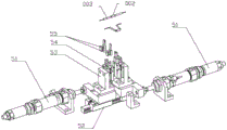
The rubber tube cutting and feeding device shown in fig. 6 comprises a rubber tube coiling and feeding assembly 41 and a rubber tube sleeving assembly 42, wherein the rubber tube coiling and feeding assembly 41 is used for placing coiled rubber tubes and slowly feeding the rubber tubes; the rubber tube sleeving component 42 is used for cutting, clamping and rubber tube sleeving; the rubber tube coiling and feeding assembly 41 comprises a vertical support 411, a winding disc 412, a feeding ratchet 413, a feeding claw 414, a feeding swing arm 415 and a feeding cylinder 416; the vertical support 411 is fixedly arranged on the frame, a connecting shaft is arranged at the upper end of the vertical support 411, the winding disc 412 is rotatably connected to the connecting shaft at the upper end of the vertical support 411, and a coiled rubber pipe is arranged on the winding disc 412; the feeding ratchet 413 is fixedly connected to the connecting shaft of the vertical support 411 and is coaxial with the winding disc 412; one end of the feeding swing arm 415 is provided with a round hole which is rotationally connected with the connecting shaft, the other end of the feeding swing arm 415 is provided with a feeding claw 414, and the feeding claw 414 is tightly pressed on the feeding ratchet 413 by a spring; the lower end of the feeding cylinder 416 is hinged with the vertical support 411, and the upper end of the feeding cylinder 416 is hinged with the feeding swing arm 415; the rubber tube sleeving component 42 comprises a mounting side plate 421, a driving motor 422, a driving gear 423, a driving rack 424, a transverse moving plate 425, a clamping cylinder 426, a clamping block 427, a material passing seat 428, a material pressing block 429, a material breaking detector 4210, a shearing cylinder 4211, a shearing knife 4212 and a material passing groove plate 4213; the mounting side plate 421 is fixedly arranged on the frame, the driving motor 422 is fixedly arranged on the mounting side plate 421, the driving gear 423 is mounted at the output end of the driving motor 422, and the driving gear 423 is meshed with the driving rack 424; the traverse plate 425 is movably matched on the mounting side plate 421 through a sliding rail assembly, and the driving rack 424 is mounted on the traverse plate 425; the clamping cylinder 426 is arranged at the end part of the traverse plate 425, and the clamping blocks 427 are fixedly arranged at the two telescopic ends of the clamping cylinder 426; the material passing base 428 is fixed on the side of the mounting side plate 421, a round hole for the rubber tube to pass through is arranged in the material passing base 428, a groove is arranged on the material passing base 428, and the groove is penetrated through the round hole; the material pressing block 429 is folded, the turning part is rotatably connected with the mounting side plate 421 through a pin shaft, and the material pressing block 429 is positioned in a groove of the material passing seat 428 and pressed on the surface of the rubber pipe; the material breakage detector 4210 is arranged on the mounting side plate 421 and is in contact with the vertical part of the material pressing block 429, and the material breakage detector 4210 is a proximity switch; the shearing cylinder 4211 is arranged on the mounting side plate 421, the shearing knife 4212 is arranged on two telescopic ends of the shearing cylinder 4211, and the height of the shearing knife 4212 is flush with that of the material passing seat 428; a material passing groove plate 4213 is arranged on the side surface of the mounting side plate 421, a vertical through groove is formed in the material passing groove plate 4213, and the rubber pipe is located in the through groove.
When the rubber tube cutting and feeding device works, the feeding cylinder 416 stretches back and forth to drive the feeding swing arm 415 to rotate, and the winding disc 412 rotates in a stepping mode through ratchet transmission to realize stepping feeding; the rubber tube enters the material passing seat 428 through the material trough plate 4213 and is pressed by the material pressing block 429, the material breaking detector 4210 has no signal, when the rubber tube does not exist at the lower end of the material pressing block 429, the rubber tube is turned over for a certain angle and is detected by the material breaking detector 4210, and a material supplementing signal is sent; the rubber tube flows out of the material passing seat 428 and then passes through the shearing knife 4212, the end part of the rubber tube is clamped by the clamping block 427, the rear driving motor 422 is clamped to rotate, the rubber tube is driven by the gear rack to be drawn out, the shearing cylinder 4211 is closed after the rubber tube reaches the specified length, the rubber tube is sheared, the end shearing rear transverse moving plate 425 continues to move out, and the rubber tube is sleeved on terminals at two ends of the electronic element.
The rubber tube cutting and feeding device solves the problems that the feeding length of the rubber tube is difficult to control, the vibration feeding accuracy is low, and no material breakage feedback exists; compared with a pre-cut vibration feeding mode, the efficiency is higher, and the accuracy is higher; the material pressing block 429 is arranged to detect whether material is broken or not, so that the stability of the equipment is improved, and the qualification rate of products is improved.
As shown in fig. 7, the positioning device 5 has a symmetrical structure, and specifically includes an advance and retreat cylinder 51, a guide rail assembly 52, a movable positioning seat 53, a positioning finger cylinder 54 and a positioning chuck 55; the advancing and retreating cylinder 51 is installed on the frame, the telescopic end of the advancing and retreating cylinder 51 is connected with the movable positioning seat 53, and the movable positioning seat 53 is in movable fit with the frame phase through the guide rail component 52; the positioning finger cylinder 54 is vertically installed on the movable positioning seat 53, the positioning chuck 55 is installed at two telescopic ends of the positioning finger cylinder 54, the positioning chuck 55 is provided with opposite V-shaped grooves, and each V-shaped groove of the chain forms a cylindrical cavity when being closed.
When the positioning device 5 works, the two ends of the electronic element 002 are sleeved with the rubber hose 003, then the positioning finger cylinder 54 drives the positioning chuck 55 to draw close to clamp the two end terminals of the diode to realize positioning, then the second moving and taking device 6 clamps the middle PN junction position of the electronic element 002 and horizontally pulls out, and meanwhile, the two advancing and retreating cylinders 51 are matched with each other to extend to form the electronic element, so that the original linear shape is changed into the folded shape, and the rubber hose is not easy to fall out.
As shown in fig. 8, the sorting device 7 includes an optical fiber detecting unit 71, a defective product collecting box 72, a sorting cylinder 73, and a discharging barrel 74; the defective product collecting box 72 is arranged at the telescopic end of the sorting cylinder 73, the defective product collecting box 72 is positioned right above the blanking barrel 74, and the blanking barrel 74 is fixedly arranged on the rack; the optical fiber detection assembly 71 is positioned on the side edge of the inferior-quality product collection box 72 and is used for detecting the formed workpieces, qualified products directly fall down, unqualified products fall into the inferior-quality product collection box 72, and the qualification rate of products is improved.
When the electronic element sleeve equipment works, the electronic element sleeve equipment is processed through the following steps in sequence:
feeding electronic components: the straightening air cylinder 2110 extends and retracts back and forth to drive the swing arm 218 to swing, the pawl 219 pushes the ratchet wheel 217 to move intermittently, so that the lower gear 213 is driven to rotate step by step, metal terminals at two ends of the electronic element are located in the tooth bottom of the lower gear 213 and are pressed by the tooth top of the upper gear 214 at the upper end, the straightness is improved, and the pressing force can be controlled through an adjusting handle 2161 of the upper pressing plate 216; the electronic components are aligned and horizontally conveyed into the rack driving assembly 22, the transverse moving cylinder 224 and the longitudinal moving cylinder 225 jointly control the movable rack seat 223 to move a rectangular track in a vertical plane, and the electronic components placed between the teeth of the fixed rack seat 222 are conveyed forward by a distance of one tooth pitch each time; after the electronic component reaches the cutting bottom plate 232, the cutting cylinder 233 drives the cutter holder 234 to descend, the press block 236 presses the lead terminal of the electronic component at first, then the cutter 235 descends, the redundant lead terminal of the electronic component is cut, the waste material falls down and slides out from the discharge chute 237.
(II) rubber tube feeding sleeve: the feeding cylinder 416 stretches back and forth to drive the feeding swing arm 415 to rotate, and the winding disc 412 rotates in a stepping mode through ratchet transmission to achieve stepping feeding; the rubber tube enters the material passing seat 428 through the material trough plate 4213 and is pressed by the material pressing block 429, the material breaking detector 4210 has no signal, when the rubber tube does not exist at the lower end of the material pressing block 429, the rubber tube is turned over for a certain angle and is detected by the material breaking detector 4210, and a material supplementing signal is sent; the rubber tube flows out of the material passing seat 428 and then passes through the shearing knife 4212, the end part of the rubber tube is clamped by the clamping block 427, the rear driving motor 422 is clamped to rotate, the rubber tube is driven by the gear rack to be drawn out, the shearing cylinder 4211 is closed after the rubber tube reaches the specified length, the rubber tube is sheared, the end shearing rear transverse moving plate 425 continues to move out, and the rubber tube is sleeved on terminals at two ends of the electronic element.
(III) forming and bending: after the two ends of the electronic element 002 are sleeved with the rubber tube 003, the positioning finger cylinder 54 drives the positioning chuck 55 to draw close, and the terminals at the two ends of the diode are clamped, so that positioning is realized; then the second moving device 6 clamps the middle PN junction part of the electronic element 002, horizontally pulls out, and simultaneously the two advancing and retreating cylinders 51 are matched with extension to form the electronic element, the original linear shape is changed into the folding shape, and the rubber tube is not easy to fall out.
(IV) sorting and blanking: the optical fiber detection assembly 71 detects the products clamped by the second moving and taking device 6, the qualified products directly fall into the blanking barrel 74, the collection is completed, and the unqualified products fall into the defective product collection box 72.
The previous description of the disclosed embodiments is provided to enable any person skilled in the art to make or use the present invention, including any reference to the above-mentioned embodiments. Various modifications to these embodiments will be readily apparent to those skilled in the art. The general principles defined herein may be implemented in other embodiments without departing from the spirit or scope of the invention. Thus, the present invention is not intended to be limited to the embodiments shown herein but is to be accorded the widest scope consistent with the principles and novel features disclosed herein.