CN110911235A - Circuit breaker magnetic tripping core assembly welding system - Google Patents
Circuit breaker magnetic tripping core assembly welding system Download PDFInfo
- Publication number
- CN110911235A CN110911235A CN201911167846.3A CN201911167846A CN110911235A CN 110911235 A CN110911235 A CN 110911235A CN 201911167846 A CN201911167846 A CN 201911167846A CN 110911235 A CN110911235 A CN 110911235A
- Authority
- CN
- China
- Prior art keywords
- coil
- pushing
- stamping
- chuck
- clamping
- Prior art date
- Legal status (The legal status is an assumption and is not a legal conclusion. Google has not performed a legal analysis and makes no representation as to the accuracy of the status listed.)
- Pending
Links
Images


Classifications
-
- H—ELECTRICITY
- H01—ELECTRIC ELEMENTS
- H01H—ELECTRIC SWITCHES; RELAYS; SELECTORS; EMERGENCY PROTECTIVE DEVICES
- H01H69/00—Apparatus or processes for the manufacture of emergency protective devices
-
- B—PERFORMING OPERATIONS; TRANSPORTING
- B23—MACHINE TOOLS; METAL-WORKING NOT OTHERWISE PROVIDED FOR
- B23K—SOLDERING OR UNSOLDERING; WELDING; CLADDING OR PLATING BY SOLDERING OR WELDING; CUTTING BY APPLYING HEAT LOCALLY, e.g. FLAME CUTTING; WORKING BY LASER BEAM
- B23K1/00—Soldering, e.g. brazing, or unsoldering
- B23K1/0008—Soldering, e.g. brazing, or unsoldering specially adapted for particular articles or work
- B23K1/0016—Brazing of electronic components
-
- B—PERFORMING OPERATIONS; TRANSPORTING
- B23—MACHINE TOOLS; METAL-WORKING NOT OTHERWISE PROVIDED FOR
- B23K—SOLDERING OR UNSOLDERING; WELDING; CLADDING OR PLATING BY SOLDERING OR WELDING; CUTTING BY APPLYING HEAT LOCALLY, e.g. FLAME CUTTING; WORKING BY LASER BEAM
- B23K3/00—Tools, devices, or special appurtenances for soldering, e.g. brazing, or unsoldering, not specially adapted for particular methods
- B23K3/06—Solder feeding devices; Solder melting pans
-
- B—PERFORMING OPERATIONS; TRANSPORTING
- B23—MACHINE TOOLS; METAL-WORKING NOT OTHERWISE PROVIDED FOR
- B23K—SOLDERING OR UNSOLDERING; WELDING; CLADDING OR PLATING BY SOLDERING OR WELDING; CUTTING BY APPLYING HEAT LOCALLY, e.g. FLAME CUTTING; WORKING BY LASER BEAM
- B23K3/00—Tools, devices, or special appurtenances for soldering, e.g. brazing, or unsoldering, not specially adapted for particular methods
- B23K3/08—Auxiliary devices therefor
Abstract
The invention discloses a welding system for a magnetic tripping core assembly of a circuit breaker, relates to the field of circuit breaker part processing, and solves the problems of tedious and slow manual operation, poor product quality and the like in the process of processing a magnetic coil assembly at the present stage. The automatic coil stamping and conveying device comprises automatic coil stamping and conveying equipment, a turntable device, a coil feeding device, a wiring board feeding device, a static contact feeding device, a solder feeding device, a wiring board welding device, a static contact welding device and a discharging device; the automatic coil stamping and conveying equipment comprises a stamping machine and a stamping and conveying device arranged on the stamping machine, wherein the stamping machine performs stamping and flattening actions on shaft ends of coils on the stamping and conveying device at intervals. The automatic welding assembly line for the magnetic tripping core assembly of the circuit breaker is formed, the automation degree is high, product parts do not need to be transferred in the whole machining process, the procedures are simple and orderly, the welding machining efficiency is greatly improved, the labor cost is saved, and the product qualified rate is high.
Description
Technical Field
The invention relates to the field of circuit breaker part processing, in particular to a circuit breaker magnetic trip core assembly welding system.
Background
The magnetic tripping core component in the circuit breaker comprises a coil, a wiring board and a fixed contact (as shown in figure 1), wherein the wiring board and the fixed contact are respectively welded on shaft ends extending from two ends of the coil through a spot welding technology, in the processing process, the shaft end of the coil needs to be firstly flattened so as to be convenient for the subsequent welding of the wiring board or the fixed contact, and then corresponding parts need to be welded at the flattened position. However, in the current stage, except for the flattening operation, a stamping machine can be used for stamping, and during the welding, a simple welding fixture is used for processing, and generally, the first fixture is used for welding the coil and the fixed contact, and then the first fixture is transferred to the second fixture for continuously welding the semi-finished product and the wiring board. The whole machining process needs to operate in three machining areas, the processes are very complicated and slow through multiple transfer, more personnel and tool equipment are needed, the occupied area is large, the labor intensity of workers is high, the cost is high, and the automation degree is low. In the transfer process of the processing area, the welding effect is poor due to the possibility of occurrence of positioning deviation because the welding area needs to be repositioned, the product quality is reduced, and the product yield is influenced.
Disclosure of Invention
The purpose of the invention is as follows: in order to overcome the defects of the prior art, the invention provides a welding system of a magnetic trip core component of a circuit breaker, which solves the problems of tedious and slow manual operation, high cost, low automation, poor product quality and the like in the process of processing a magnetic coil component at the present stage.
The technical scheme of the invention is as follows: the automatic coil stamping and conveying device comprises automatic coil stamping and conveying equipment, a turntable device, a coil feeding device, a wiring board feeding device, a static contact feeding device, a solder feeding device, a wiring board welding device, a static contact welding device and a discharging device; the automatic coil stamping and conveying equipment comprises a stamping machine and a stamping and conveying device arranged on the stamping machine, wherein the stamping machine performs stamping and flattening actions on shaft ends of coils on the stamping and conveying device at intervals; the rotary table device comprises a rotary table which rotates and moves, a plurality of clamps for clamping products are arranged on the rotary table, and the wiring board feeding device, the static contact feeding device, the solder feeding device, the coil feeding device, the wiring board welding device, the static contact welding device and the discharging device are respectively arranged at the peripheral opposite positions of the clamps of the rotary table according to the sequence of the rotating direction; the coil feeding device is communicated with the stamping and conveying device and is used for clamping a coil at a discharge port of the stamping and conveying device onto a corresponding clamp on the rotary workbench; a wiring board feeding device for supplying the wiring board to the corresponding clamp on the rotary worktable; the static contact feeding device supplies the static contact to the corresponding clamp on the rotary worktable; the solder feeding device supplies solder to positions to be welded of the wiring board and the fixed contact on the corresponding clamp; a wiring board welding device for welding the wiring board on the coil; the static contact welding device is used for welding a static contact on the coil; and the discharging device is used for clamping a product on the corresponding clamp and delivering the product out of the rotary table device.
By adopting the technical scheme, the coil is flattened at the end part by the automatic coil stamping and conveying equipment and then conveyed to the coil feeding device, then the coil feeding device clamps the coil on the turntable device, meanwhile, the wiring board feeding device, the static contact feeding device and the solder feeding device respectively supply wiring boards, static contacts and soldering flux to corresponding clamps, then the wiring boards are welded at corresponding positions by the wiring board welding device and the static contact welding device, and finally, a finished product is clamped out of the turntable device by the discharging device; the automatic welding assembly line for the magnetic tripping core assembly of the circuit breaker is formed, the automation degree is high, product parts do not need to be transferred in the whole machining process, the process is simple and orderly, the welding machining efficiency is greatly improved, the labor cost is saved, automatic continuous production is adopted, most of the machining processes do not need to reposition workpieces, the welded product is high in consistency, the operation accuracy is higher, the continuity and the reliability of production are well guaranteed, the product quality is obviously improved, and the product percent of pass is higher.
The invention further comprises the following steps: the punching machine is provided with a punch, and the punching and conveying device comprises a feeding conveying rail, a punching and distributing mechanism, a rail lower die and a pushing and positioning mechanism, wherein the punching and distributing mechanism, the rail lower die and the pushing and positioning mechanism are arranged between the feeding conveying rail and the feeding conveying rail; the stamping and distributing mechanism comprises a stamping and distributing seat, a stamping and distributing execution cylinder and a stamping and distributing rod fixed on an output shaft of the stamping and distributing execution cylinder, the stamping and distributing seat is fixed on a discharging position of the feeding conveying track and forms a first dropping channel with the feeding conveying track, and only a single coil drops to the lower part of the first dropping channel; the track lower die is arranged below the first falling channel to receive a coil falling from the first falling channel, a stamping working area below a punch of a punching machine and a second falling channel at the discharging position of the track lower die are arranged on the track lower die, the pushing and positioning mechanism comprises a pushing plate, a pushing execution cylinder, a positioning plate and a positioning execution cylinder, the pushing plate and the positioning plate are respectively connected to output shafts of the pushing execution cylinder and the positioning execution cylinder, the pushing plate and the positioning plate are arranged on the track lower die in a sliding manner, clamping holes for clamping two sides of the coil are formed between the pushing plate and the positioning plate, and the pushing plate and the positioning plate perform actions of sliding from the lower part of the first falling channel, staying in the stamping working area and then sliding to the second falling channel; the feeding conveying track is arranged below the second falling channel to receive coils falling from the second falling channel.
Adopt above-mentioned further setting, feeding delivery track transports the coil to punching press feed mechanism branch material, pushes away the material location by pushing away material positioning mechanism to the coil on the track lower mould, and the drift is dashed flat operation, and feeding delivery track sees off to coil material feeding unit at last, realizes coil automatic punching press and autoloading, and the coil of joining coil material feeding unit supply punching press completion avoids the multizone to shift the wasting time and energy that leads to.
The invention further provides that: the clamp comprises a clamp body, a vertical clamping assembly, a horizontal clamping assembly and a pushing driving assembly, wherein the vertical clamping assembly and the horizontal clamping assembly are movably connected to the clamp body; the vertical clamping assembly comprises a coil clamping piece, a coil lower die and a first restoring piece, the coil clamping piece is movably arranged on the clamp body along the vertical direction, a coil clamping area is formed between the coil clamping piece and the coil lower die fixed on the clamp body, and the first restoring piece is fixed on the coil clamping piece, is abutted against the clamp body and is used for providing restoring force for a coil clamped in the coil clamping area by the coil clamping piece; the horizontal clamping assembly comprises two horizontal clamping arms, a fixed contact positioning die, a wiring board lower die, a second return piece and a third return piece, the two horizontal clamping arms are movably arranged on the clamp body along the horizontal direction, and the two horizontal clamping arms are oppositely arranged; a clamping area for a fixed contact is formed between one horizontal clamping arm and a fixed contact positioning die fixed on the clamp main body, a clamping area for a wiring board is formed between the other horizontal clamping arm and one side face of the lower coil die, and the lower wiring board die is used for positioning the bottom face of the wiring board; the second restoring piece and the third restoring piece are respectively fixed on the two horizontal clamping arms and are respectively abutted against the clamp body, and are used for providing restoring force for the corresponding horizontal clamping arms; the pushing driving assembly is matched with the first restoring piece, the second restoring piece and the third restoring piece respectively so as to provide driving force for moving the coil clamping piece and the horizontal clamping arm.
Adopt above-mentioned still further setting, perpendicular centre gripping subassembly is used for centre gripping coil, and horizontal centre gripping subassembly can centre gripping static contact and wiring board, and the application promotes drive assembly and promotes corresponding reply piece and can loosen corresponding centre gripping, reasonable in design.
Still further arrangements of the invention are: the wiring board feeding device and the static contact feeding device respectively comprise a vibration disc, a linear vibration track, a material distributing mechanism and a material pushing mechanism, wherein the linear vibration track is arranged at the discharge port of the vibration disc, the material distributing mechanism is arranged at the tail end of the linear vibration track and performs material distributing action, and the material pushing mechanism performs action of pushing out parts on the material distributing mechanism to the corresponding position of the clamp.
By adopting the further arrangement, the wiring board and the fixed contact are firstly vibrated and output by the vibration disc and the linear vibration track, then are distributed by the distributing mechanism, and finally are pushed to the clamp of the turntable device by the pushing mechanism, so that the action design is reasonable, and the operation is smooth.
Still further arrangements of the invention are: the feed mechanism comprises a feed turntable support, a feed turntable, a turntable rotary driving piece and a feed detection sensor, the feed turntable is rotatably mounted on the feed turntable support, a feed hole for feeding a single part is formed in the feed turntable, the appearance of the feed hole is matched with the appearance of the pre-fed part, an output shaft of the turntable rotary driving piece is connected with the feed turntable to drive the feed turntable to rotate to a feed hole and pushing mechanism communicating state from the feed hole and linear vibration track communicating state, and the detection range of the feed detection sensor is located on the feed hole and is electrically connected with the feed detection sensor and the turntable rotary driving piece.
By adopting the further arrangement, the linear vibration rail conveys the parts to the material holes, and the single part is rotationally separated by the material separating turntable and is transferred to be communicated with the material pushing mechanism.
Still further arrangements of the invention are: the pushing mechanism comprises a pushing sheet, a pushing frame, a pushing seat and a pushing driving cylinder, the pushing sheet fixing frame is arranged on the pushing frame, the end part of the pushing sheet fixing frame penetrates into the distribution turntable support, the pushing sheet also movably penetrates through a material hole which is communicated with the pushing mechanism, and the appearance of the pushing sheet in the moving direction is matched with that of the pre-feeding part; the material pushing frame is coaxially and fixedly connected with an output shaft of the material pushing driving cylinder and is in sliding fit with the material pushing seat through a slide block guide rail pair.
By adopting the above further arrangement, the material pushing sheet penetrates through the material pushing hole, and the part in the material pushing hole is pushed to the clamp.
Still further arrangements of the invention are: solder feedway is including the feed chuck seat of removable chuck, draw material mechanism, cut mechanism and suction nozzle and move material mechanism, be provided with the chuck of supply non-wafer solder on the feed chuck seat, draw material mechanism and set up the non-wafer in the discharge gate department that introduces the chuck in the chuck of chuck, draw material mechanism still with cut the mechanism intercommunication in order to draw the non-wafer to cutting the mechanism, cut the mechanism and make the spaced action that cuts the non-wafer, the suction nozzle moves material mechanism and moves material sharp module including suction nozzle spare, vacuum generator and the suction nozzle that is used for removing the suction nozzle spare, the suction nozzle spare sets up on sharp module, offer the suction hole that is used for inhaling the non-wafer on the suction nozzle spare, suction hole and vacuum generator intercommunication.
According to the above further arrangement, the non-crystal piece soldering flux in the chuck is led out by the material leading mechanism, is cut into sections by the cutting mechanism, is sucked by the vacuum generator to form negative pressure, so that the suction nozzle piece sucks up the section-shaped non-crystal piece, and the section-shaped non-crystal piece is moved by the suction nozzle material moving linear module and is sent to the clamp.
Still further arrangements of the invention are: a correcting device used for correcting the arrangement position of the coil on the corresponding clamp is arranged between the coil feeding device and the wiring board welding device; the correcting device comprises a radial pressure head, an axial chuck, a pressure head driving cylinder and a chuck driving finger cylinder, wherein the pressure head driving cylinder and the chuck driving finger cylinder respectively drive the radial pressure head and the axial chuck, the axial chuck is close to a coil on the clamp and clamps two ends of the coil, the radial pressure head is provided with a step attached to a preset position, and when the radial pressure head is close to the coil flattening position, the step is abutted to the coil flattening position.
By adopting the further arrangement, after the two ends of the coil are clamped by the axial chuck, the radial pressure head is adjusted to the position pre-adjusted by the step, and the position of the coil is corrected so as to meet the qualified requirement.
Still further arrangements of the invention are: the wiring board welding device and the static contact welding device respectively comprise a welding machine and an output current detection module, and the output current detection module is used for detecting whether the output current of the welding machine reaches a preset output value.
By adopting the above further arrangement, whether the output current of the welding machine reaches the preset output value or not can be detected through the output current detection module so as to verify whether welding at the welding position is qualified or not.
Still further arrangements of the invention are: the discharging device comprises a movable discharging clamping mechanism close to the clamp and a recycling mechanism capable of being used for distinguishing genuine products and waste products, wherein the discharging clamping mechanism comprises a static chuck, a movable chuck and a pushing head located between the static chuck and the movable chuck, the movable chuck is movably arranged above the static chuck to clamp products located between the static chuck and the movable chuck, and the pushing head pushes the products between the static chuck and the movable chuck to drop onto the recycling mechanism.
By adopting the above further arrangement, the movable chuck moves close to the static chuck to clamp the product, and the pushing head pushes out the product between the static chuck and the movable chuck to enable the product to fall onto the recovery mechanism.
Drawings
Fig. 1 is a schematic structural view of a magnetic trip core assembly of the present invention;
FIG. 2 is a schematic structural diagram of an embodiment of the present invention;
FIG. 3 is a top view of an embodiment of the present invention;
FIG. 4 is a schematic structural view of an automatic coil stamping and feeding apparatus according to the present invention;
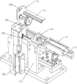
FIG. 5 is a sectional perspective view of the press feed device of the present invention;
FIG. 6 is a schematic view of the structure of the clamp of the present invention;
FIG. 7 is a perspective view in half section of the clamp of the present invention;
fig. 8 is a schematic structural view of a static contact feeding device according to the present invention;
fig. 9 is an exploded view of a static contact feeding device according to the present invention;
FIG. 10 is a schematic view of a solder feeding apparatus according to the present invention;
FIG. 11 is a schematic structural diagram of a correction device according to the present invention;
FIG. 12 is a schematic structural view of a discharging device according to the present invention;
wherein, the magnetic tripping core component 10, the coil 101, the wiring board 102, the static contact 103, the automatic coil stamping and conveying device 1, the turntable device 2, the coil feeding device 3, the wiring board feeding device 4, the static contact feeding device 5, the solder feeding device 6, the wiring board welding device 71, the static contact welding device 72, the discharging device 8, the punch 11, the stamping and conveying device 12, the rotary table 21, the clamp 9, the punch 111, the feeding and conveying rail 121, the feeding and conveying rail 122, the stamping and distributing mechanism 13, the rail lower die 14, the pushing and positioning mechanism 15, the stamping and distributing seat 131, the stamping and distributing execution cylinder 132, the stamping and distributing rod 133, the first dropping channel 134, the stamping working area 141, the second dropping channel 142, the pushing plate 151, the pushing execution cylinder 152, the positioning plate 153, the positioning execution cylinder 154, the clamp body 91, the vertical clamping component 92 and the horizontal clamping component 93, the pushing driving assembly 94, the coil clamping member 921, the coil lower die 922, the first restoring member 923, the horizontal clamping arm 931, the static contact positioning die 932, the wiring board lower die 933, the second restoring member 934, the third restoring member 935, the vibration disc 51, the linear vibration rail 52, the material separating mechanism 53, the material pushing mechanism 54, the material separating disc support 531, the material separating disc 532, the disc rotation driving member 533, the material separating detection sensor 534, the material hole 5321, the material pushing sheet 541, the material pushing sheet 542, the material pushing seat 543, the material pushing driving cylinder 544, the material feeding disc seat 61, the material guiding mechanism 62, the cutting mechanism 63, the suction nozzle material moving mechanism 64, the chuck 611, the suction nozzle member 641, the material moving linear module 642, the suction hole 6411, the correcting device 20, the radial pressure head 201, the axial pressure head 202, the pressure head driving cylinder 203, the pressure head driving finger welding machine cylinder 204, the step 2011, 711, the material discharging clamping mechanism 81, the recovering mechanism 82, a movable clamping head 812 and a pushing head 813.
Detailed Description
As shown in fig. 2 and fig. 3, the system for welding the magnetic tripping core assembly of the circuit breaker includes a coil automatic stamping material conveying device 1, a turntable device 2, a coil feeding device 3, a wiring board feeding device 4, a static contact feeding device 5, a solder feeding device 6, a wiring board welding device 71, a static contact welding device 72, and a discharging device 8; the automatic coil stamping and conveying equipment 1 comprises a stamping machine 11 and a stamping and conveying device 12 arranged on the stamping machine 11, wherein the stamping machine 11 performs stamping and flattening actions on the shaft ends of a coil 101 on the stamping and conveying device 12 at intervals, and the shaft ends of the coil 101 are positioned at two outer sides of the coil 101; the rotary table device 2 comprises a rotary table 21 which rotates and moves, the rotary table 21 is composed of a divider, a plurality of clamps 9 for clamping products are arranged on the rotary table 21 every time the rotary table 21 rotates for a period of time at a preset angle, and a wiring board feeding device 4, a static contact feeding device 5, a solder feeding device 6, a coil feeding device 3, a wiring board welding device 71, a static contact welding device 72 and a discharging device 8 are respectively arranged at the peripheral opposite positions of the clamps 9 of the rotary table 21 according to the sequence of the rotating direction; the coil feeding device 3 is communicated with the stamping and conveying device 12 and is used for clamping the coil 101 at the discharge port of the stamping and conveying device 12 onto the corresponding clamp 9 on the rotary workbench 21; a terminal plate supply device 4 that supplies the terminal plate 102 to the corresponding jig 9 on the rotary table 21; the static contact feeding device 5 is used for supplying the static contact 103 to the corresponding clamp 9 on the rotary worktable 21; a solder feeding device 6 for supplying solder such as flux to the positions to be soldered corresponding to the wiring board 102 and the stationary contact 103 on the jig 9; a terminal plate soldering device 71 which solders a terminal plate 102 to the coil 101; the static contact welding device 72 is used for welding a static contact 103 on the coil 101; and the discharging device 8 is used for clamping the product on the corresponding clamp 9 and sending the product out of the rotary table device 2. The automatic coil stamping and conveying equipment 1 flattens the shaft end of the coil, then conveys the shaft end to the coil feeding device 3, and then clamps the shaft end to the clamp 9 of the turntable device 2 by the coil feeding device 3; synchronously, the wiring board feeding device 4 and the static contact feeding device 5 sequentially and respectively supply the wiring board 102 and the static contact 103 to the corresponding fixture 9, the solder feeding device 6 supplies soldering flux to the welding position of the shaft end of the coil 101, then the wiring board welding device 71 and the static contact welding device 72 respectively weld the welding position, and finally the discharging device 8 clamps the finished product out of the turntable device 8.
As shown in fig. 4 and 5, the punch 111 is provided on the punch 11, and the punch feeding device 12 includes a feeding conveying rail 121, a feeding conveying rail 122, and a punch separating mechanism 13, a rail lower die 14, and a pushing positioning mechanism 15 which are provided between the feeding conveying rail 121 and the feeding conveying rail 122. The stamping and distributing mechanism 13 includes a stamping and distributing seat 131, a stamping and distributing execution cylinder 132, and a stamping and distributing rod 133 fixed to an output shaft of the stamping and distributing execution cylinder 132, the stamping and distributing seat 131 is fixed to a discharging position of the feeding conveying rail 121, a first dropping channel 123 for allowing only a single coil 101 to drop to the lower side is formed between the stamping and distributing seat 131 and the feeding conveying rail 121, and the stamping and distributing rod 133 is slidably disposed on the stamping and distributing seat 131 for opening or closing the first dropping channel 134. The lower rail mold 14 is disposed below the first drop passage 134 to receive the coil 101 dropped from the first drop passage 134, and the lower rail mold 14 has a punching work area 141 below the punch 111 of the punching machine 11 and a second drop passage 142 at a discharge position of the lower rail mold 14. The material pushing and positioning mechanism 15 comprises a material pushing plate 151, a material pushing execution cylinder 152, a positioning plate 153 and a positioning execution cylinder 154, the material pushing plate 151 and the positioning plate 153 are respectively connected to output shafts of the material pushing execution cylinder 152 and the positioning execution cylinder 154, the material pushing plate 151 and the positioning plate 153 are arranged on the lower rail die 14 in a sliding manner, a clamping hole for clamping two sides of the coil 101 is formed between the material pushing plate 151 and the positioning plate 153, and the material pushing plate 151 and the positioning plate 153 perform actions of sliding from the lower part of the first dropping channel 134, staying in the stamping working area 141 and sliding to the second dropping channel 142; the feeding conveying rail 122 is disposed below the second dropping channel 142 to receive the coil 101 dropped by the second dropping channel 142. The main parts of the feeding conveying track 121, the feeding conveying track 122 and the track lower die 14 are arranged horizontally, and the first dropping channel 134 and the second dropping channel 142 are arranged vertically. The feeding conveying track 121 conveys the coils 101 to the punching and distributing seat 131, the punching and distributing rod 133 slides out of the first dropping channel 134 to open the first dropping channel 134, the single coil 101 drops from the first dropping channel 134 onto the track lower die 14, and the punching and distributing rod 133 closes the first dropping channel 134 at the same time; the material pushing plate 151 pushes the dropped coil 101 to the punching working area 141, the positioning plate 153 surrounds and clamps the coil 101 with the material pushing plate 151, so that the coil 101 is positioned in the punching working area, at this time, the punch 111 is pressed down to perform the flattening operation, after the operation is finished, the material pushing plate 151 and the positioning plate 153 push the coil to the inlet of the second dropping channel 142, and then the coil drops to the feeding conveying rail 122 below through the second dropping channel 142, and finally the coil is sent out of the punching conveying device 12 through the feeding conveying rail 122.
As shown in fig. 6 and 7, the clamp 9 includes a clamp main body 91, a vertical clamping assembly 92, a horizontal clamping assembly 93, and a pushing driving assembly 94, wherein the vertical clamping assembly 92 and the horizontal clamping assembly 93 are movably coupled to the clamp main body 91; the vertical clamping assembly 92 comprises a coil clamping piece 921, a coil lower die 922 and a first restoring piece 923, wherein the coil clamping piece 921 is movably arranged on the clamp body 91 along the vertical direction, a coil clamping area is formed between the coil clamping piece 921 and the coil lower die 922 fixed on the clamp body 91, and the first restoring piece 923 is fixed on the coil clamping piece 921 and is abutted against the clamp body 91 and is used for providing restoring force for the coil 101 clamped by the coil clamping piece 921 in the coil clamping area; the horizontal clamping assembly 93 comprises two horizontal clamping arms 931, a fixed contact positioning die 932, a wiring board lower die 933, a second recovery piece 934 and a third recovery piece 935, the two horizontal clamping arms 931 are movably arranged on the clamp body 91 along the horizontal direction, and the two horizontal clamping arms 931 are oppositely arranged; a static contact clamping area is formed between one horizontal clamping arm 931 and a static contact positioning die 932 fixed on the clamp body 91, a wiring board clamping area is formed between the other horizontal clamping arm 931 and one side surface of the coil lower die 922, and the wiring board lower die 933 is used for positioning the bottom surface of the wiring board 102; the second restoring member 934 and the third restoring member 935 are respectively fixed to the two horizontal clamping arms 931 and respectively abutted against the clamp body 91, and are configured to provide restoring force for the corresponding horizontal clamping arms 931; the pushing driving assembly 94 cooperates with the first restoring member 923, the second restoring member 934, and the third restoring member 935, respectively, to provide a driving force for the coil holder 921 and the horizontal arm 931 to move. The coil clamping piece 921 and the coil lower die 922 are used for positioning and clamping the coil 101, one of the horizontal clamping arm 931 and the fixed contact positioning die 932 is used for positioning and clamping the fixed contact 103, and the other horizontal clamping arm 931, one side face of the coil lower die 922 and the wiring board lower die 933 are used for positioning and clamping the wiring board 102. When the clamp 9 needs to be opened, the pushing driving assembly 94 drives the corresponding first, second and third restoring members 923, 934 and 935 to release the corresponding clamping portions.
As shown in fig. 8 and 9, each of the terminal block feeding device 4 and the fixed contact feeding device 5 includes a vibrating tray 51, a linear vibrating track 52, a material distributing mechanism 53 and a material pushing mechanism 54, the linear vibrating track 52 is disposed at a discharge port of the vibrating tray 51, the material distributing mechanism 53 is disposed at a tail end of the linear vibrating track 52 and performs material distributing operation, and the material pushing mechanism 54 performs operation of pushing out a part on the material distributing mechanism 53 to a position corresponding to the fixture 9. The corresponding parts such as the wiring board 102 and the fixed contact 103 are firstly vibrated and output by the vibration disc 51 and the linear vibration track 52, then are distributed by the distributing mechanism 53, and finally are pushed out of the parts on the distributing mechanism 53 by the pushing mechanism 54 to the corresponding positions of the clamp 9.
The material distributing mechanism 53 includes a material distributing turntable support 531, a material distributing turntable 532, a turntable rotary driving member 533 and a material distributing detecting sensor 534, the material distributing turntable 532 is rotatably mounted on the material distributing turntable support 531, a material hole 5321 for feeding a single part is formed in the material distributing turntable 532, the shape of the material hole 5321 is matched with the shape of the pre-fed part, an output shaft of the turntable rotary driving member 533 is connected with the material distributing turntable 532 to drive the material distributing turntable 532 to rotate from the state that the material hole 5321 is communicated with the linear vibration track 52 to the state that the material hole 5321 is communicated with the material pushing mechanism 54, the detecting range of the material distributing detecting sensor 534 is located on the material hole 5321, and the material distributing detecting sensor 534 is electrically connected with the turntable rotary driving member. The linear vibration track 52 conveys corresponding parts such as the wiring board 102 and the fixed contact 103 to the material hole 5321 of the material distribution turntable 532, when the material distribution detection sensor 534 detects that the material is fed into the material hole 5321, the turntable rotating driving piece 533 drives the material distribution turntable 532 to rotate, the material distribution turntable 532 rotates to be communicated with the material pushing mechanism 54, and a single part is separated to the next process.
The pushing mechanism 54 comprises a pushing sheet 541, a pushing frame 542, a pushing seat 543 and a pushing driving cylinder 544, the pushing sheet 541 is fixedly arranged on the pushing frame 542, the end part of the pushing sheet penetrates into the material distribution turntable bracket 531, the pushing sheet 541 also movably penetrates through a material hole communicated with the pushing mechanism 54, and the shape of the moving direction of the pushing sheet 541 is matched with the shape of the pre-loaded part; the material pushing frame 542 is coaxially and fixedly connected with an output shaft of the material pushing driving cylinder 544 and is in sliding fit with the material pushing seat 543 through a slide block guide rail pair. When the material hole 5321 of the material distributing turntable 532 rotates to be communicated with the material pushing mechanism 54, the material pushing sheet 541 and the material hole 5321 are in a collinear position, the material pushing driving cylinder 544 drives the material pushing frame 542 to slide on the material pushing seat 543, so that the material pushing sheet 541 is driven to penetrate towards the material hole 5321, and a part in the material hole 5321 is pushed out to the clamp 9.
As shown in fig. 10, the solder feeding device 6 includes a feeding chuck base 61 with a replaceable chuck, a material guiding mechanism 62, a cutting mechanism 63, and a nozzle moving mechanism 64, the chuck 611 is disposed on the feeding chuck base 61 for supplying non-wafer solder, the material guiding mechanism 62 is disposed at a discharge port of the chuck 611 for guiding the non-wafer in the chuck 611, the material guiding mechanism 62 is further communicated with the cutting mechanism 63 for guiding the non-wafer to the cutting mechanism 63, the cutting mechanism 63 cuts the non-wafer at intervals, the nozzle moving mechanism 64 includes a nozzle 641, a vacuum generator, and a nozzle moving linear module 642 for moving the nozzle 641, the nozzle is disposed on the linear module, a suction hole 6411 for sucking up the non-wafer is disposed on the nozzle 641, a suction port of the suction hole 6411 is disposed on a bottom surface of the nozzle, and the suction hole 6411 is communicated with the vacuum generator. The guiding mechanism 62 guides the amorphous piece flux in the chuck 611 and sends the amorphous piece flux to the cutting mechanism 63, the amorphous piece flux is cut into segments by the cutting mechanism 63 at intervals, then the segment-shaped amorphous piece flux is sucked by the vacuum generator to form a negative pressure of the nozzle 641, the nozzle 641 sucks up the segment-shaped amorphous piece, and finally the nozzle shifting linear module 642 moves the nozzle 641 to send the amorphous piece flux to the corresponding clamp 9 to put down the amorphous piece.
As shown in fig. 11, a correcting device 20 for correcting the placement position of the coil 101 on the corresponding clamp 9 is arranged between the coil feeding device 3 and the wiring board welding device 4; the correcting device 20 comprises a radial pressure head 201, an axial chuck 202, a pressure head driving air cylinder 203 for driving the radial pressure head 201 to act, and a chuck driving finger air cylinder 204 for driving the axial chuck 202 to act, wherein the axial chuck 202 is close to the coil 101 on the clamp 9 and clamps the end surfaces of two ends of the coil 101, the radial pressure head 201 is provided with a step 2011 attached to a preset position, and when the radial pressure head 201 is close to the flattening position of the coil 101, the step 2011 is abutted to the flattening position of the coil 101. After the axial collet 202 moves to approach and clamp the end faces of the two ends of the coil 101, the radial ram 101 moves to approach, the step 2011 abuts against the flattened part of the coil 101, so that the coil 101 is adjusted to the required position in the shape of the step 2011, and the position of the coil 101 is adjusted to the required position.
The wiring board welding device 71 and the static contact welding device 72 each include a welding machine 711 and an output current detection module, and the output current detection module is used for detecting whether the output current of the welding machine 711 reaches a preset output value. When the welding machine 711 is in welding, the output current of the welding machine is detected by the output current detection module, and if the output current reaches a preset output value, the welding is qualified; otherwise, the output value does not reach the preset output value, and the product is regarded as unqualified.
As shown in fig. 12, the discharging device 8 includes a discharging clamping mechanism 81 movable close to the clamp and a recycling mechanism 82 for distinguishing genuine products and waste products, the discharging clamping mechanism 81 includes a static chuck 811, a dynamic chuck 812 and a pushing head 813 positioned between the static chuck 811 and the dynamic chuck 812, the dynamic chuck 812 is movably disposed above the static chuck 811 to clamp the products positioned between the static chuck 811 and the dynamic chuck 812, and the pushing head 813 pushes the products between the static chuck 811 and the dynamic chuck 812 to drop onto the recycling mechanism 82. The movable jaw 812 moves closer to the static jaw 812 for gripping the product and moves out, and the rear pusher pushes the product between the static jaw 811 and the movable jaw 812 to drop the product onto the recovery mechanism 82.
Claims (10)
1. The utility model provides a circuit breaker magnetic trip core subassembly welding system which characterized in that: the automatic coil stamping and conveying device comprises automatic coil stamping and conveying equipment, a turntable device, a coil feeding device, a wiring board feeding device, a static contact feeding device, a solder feeding device, a wiring board welding device, a static contact welding device and a discharging device;
the automatic coil stamping and conveying equipment comprises a stamping machine and a stamping and conveying device arranged on the stamping machine, wherein the stamping machine performs stamping and flattening actions on shaft ends of coils on the stamping and conveying device at intervals;
the rotary table device comprises a rotary table which rotates and moves, a plurality of clamps for clamping products are arranged on the rotary table, and the wiring board feeding device, the static contact feeding device, the solder feeding device, the coil feeding device, the wiring board welding device, the static contact welding device and the discharging device are respectively arranged at the peripheral opposite positions of the clamps of the rotary table according to the sequence of the rotating direction;
the coil feeding device is communicated with the stamping and conveying device and is used for clamping a coil at a discharge port of the stamping and conveying device onto a corresponding clamp on the rotary workbench;
a wiring board feeding device for supplying the wiring board to the corresponding clamp on the rotary worktable;
the static contact feeding device supplies the static contact to the corresponding clamp on the rotary worktable;
the solder feeding device supplies solder to positions to be welded of the wiring board and the fixed contact on the corresponding clamp;
a wiring board welding device for welding the wiring board on the coil;
the static contact welding device is used for welding a static contact on the coil;
and the discharging device is used for clamping a product on the corresponding clamp and delivering the product out of the rotary table device.
2. The circuit breaker magnetic trip core assembly welding system of claim 1, wherein: the punching machine is provided with a punch, and the punching and conveying device comprises a feeding conveying rail, a punching and distributing mechanism, a rail lower die and a material pushing and positioning mechanism, wherein the punching and distributing mechanism, the rail lower die and the material pushing and positioning mechanism are arranged between the feeding conveying rail and the feeding conveying rail; the stamping and distributing mechanism comprises a stamping and distributing seat, a stamping and distributing execution cylinder and a stamping and distributing rod fixed on an output shaft of the stamping and distributing execution cylinder, the stamping and distributing seat is fixed on a discharging position of the feeding conveying track and forms a first dropping channel with the feeding conveying track, and only a single coil drops to the lower part of the first dropping channel; the track lower die is arranged below the first falling channel to receive a coil falling from the first falling channel, a stamping working area below a punch of a punching machine and a second falling channel at the discharging position of the track lower die are arranged on the track lower die, the pushing and positioning mechanism comprises a pushing plate, a pushing execution cylinder, a positioning plate and a positioning execution cylinder, the pushing plate and the positioning plate are respectively connected to output shafts of the pushing execution cylinder and the positioning execution cylinder, the pushing plate and the positioning plate are arranged on the track lower die in a sliding manner, clamping holes for clamping two sides of the coil are formed between the pushing plate and the positioning plate, and the pushing plate and the positioning plate perform actions of sliding from the lower part of the first falling channel, staying in the stamping working area and then sliding to the second falling channel; the feeding conveying track is arranged below the second falling channel to receive coils falling from the second falling channel.
3. The circuit breaker magnetic trip core assembly welding system of claim 1 or 2, wherein: the fixture comprises a fixture main body, a vertical clamping assembly, a horizontal clamping assembly and a pushing driving assembly, wherein the vertical clamping assembly and the horizontal clamping assembly are movably connected to the fixture main body in a matching mode; the vertical clamping assembly comprises a coil clamping piece, a coil lower die and a first restoring piece, the coil clamping piece is movably arranged on the clamp body along the vertical direction, a coil clamping area is formed between the coil clamping piece and the coil lower die fixed on the clamp body, and the first restoring piece is fixed on the coil clamping piece, is abutted against the clamp body and is used for providing restoring force for a coil clamped in the coil clamping area by the coil clamping piece; the horizontal clamping assembly comprises two horizontal clamping arms, a fixed contact positioning die, a wiring board lower die, a second return piece and a third return piece, the two horizontal clamping arms are movably arranged on the clamp body along the horizontal direction, and the two horizontal clamping arms are oppositely arranged; a clamping area for a fixed contact is formed between one horizontal clamping arm and a fixed contact positioning die fixed on the clamp main body, a clamping area for a wiring board is formed between the other horizontal clamping arm and one side face of the lower coil die, and the lower wiring board die is used for positioning the bottom face of the wiring board; the second restoring piece and the third restoring piece are respectively fixed on the two horizontal clamping arms and are respectively abutted against the clamp body, and are used for providing restoring force for the corresponding horizontal clamping arms; the pushing driving assembly is matched with the first restoring piece, the second restoring piece and the third restoring piece respectively so as to provide driving force for moving the coil clamping piece and the horizontal clamping arm.
4. The circuit breaker magnetic trip core assembly welding system of claim 1 or 2, wherein: the wiring board feeding device and the static contact feeding device respectively comprise a vibration disc, a linear vibration track, a material distributing mechanism and a material pushing mechanism, the linear vibration track is arranged at the discharge port of the vibration disc, the material distributing mechanism is arranged at the tail end of the linear vibration track and conducts material distributing action, and the material pushing mechanism conducts action of pushing out parts on the material distributing mechanism to the corresponding position of the clamp.
5. The circuit breaker magnetic trip core assembly welding system of claim 4, wherein: the feed mechanism comprises a feed turntable support, a feed turntable, a turntable rotary driving piece and a feed detection sensor, the feed turntable is rotatably mounted on the feed turntable support, a feed hole for feeding a single part is formed in the feed turntable, the appearance of the feed hole is matched with the appearance of the pre-fed part, an output shaft of the turntable rotary driving piece is connected with the feed turntable to drive the feed turntable to rotate to a feed hole and pushing mechanism communicating state from the feed hole and linear vibration track communicating state, and the detection range of the feed detection sensor is located on the feed hole and is electrically connected with the feed detection sensor and the turntable rotary driving piece.
6. The circuit breaker magnetic trip core assembly welding system of claim 5, wherein: the pushing mechanism comprises a pushing piece, a pushing frame, a pushing seat and a pushing driving cylinder, the pushing piece fixing frame is arranged on the pushing frame, the end part of the pushing piece fixing frame penetrates into the distribution turntable support, the pushing piece also movably penetrates through a material hole communicated with the pushing mechanism, and the appearance of the pushing piece in the moving direction is matched with that of the pre-feeding part; the material pushing frame is coaxially and fixedly connected with an output shaft of the material pushing driving cylinder and is in sliding fit with the material pushing seat through a slide block guide rail pair.
7. The circuit breaker magnetic trip core assembly welding system of claim 1 or 2, wherein: solder feedway is including the feed chuck seat of removable chuck, draw material mechanism, cut mechanism and suction nozzle and move material mechanism, be provided with the chuck of supply non-wafer solder on the feed chuck seat, draw material mechanism and set up the non-wafer in the discharge gate department that introduces the chuck in the chuck, draw material mechanism still with cut the mechanism intercommunication in order to draw the non-wafer to cutting the mechanism, cut the mechanism and make the spaced action that cuts the non-wafer, the suction nozzle moves material mechanism and moves material sharp module including suction nozzle spare, vacuum generator and the suction nozzle that is used for removing the suction nozzle spare, the suction nozzle spare sets up on sharp module, offer the suction hole that is used for inhaling the non-wafer on the suction nozzle spare, suction hole and vacuum generator intercommunication.
8. The circuit breaker magnetic trip core assembly welding system of claim 1 or 2, wherein: a correcting device used for correcting the arrangement position of the coil on the corresponding clamp is arranged between the coil feeding device and the wiring board welding device; the correcting device comprises a radial pressure head, an axial chuck, a pressure head driving cylinder and a chuck driving finger cylinder, wherein the pressure head driving cylinder and the chuck driving finger cylinder respectively drive the radial pressure head and the axial chuck, the axial chuck is close to a coil on the clamp and clamps two ends of the coil, the radial pressure head is provided with a step attached to a preset position, and when the radial pressure head is close to the coil flattening position, the step is abutted to the coil flattening position.
9. The circuit breaker magnetic trip core assembly welding system of claim 1 or 2, wherein: the wiring board welding device and the static contact welding device respectively comprise a welding machine and an output current detection module, and the output current detection module is used for detecting whether the output current of the welding machine reaches a preset output value.
10. The circuit breaker magnetic trip core assembly welding system of claim 1 or 2, wherein: the discharging device comprises a movable discharging clamping mechanism close to the clamp and a recycling mechanism capable of being used for distinguishing genuine products and waste products, wherein the discharging clamping mechanism comprises a static chuck, a movable chuck and a pushing head located between the static chuck and the movable chuck, the movable chuck is movably arranged above the static chuck to clamp products located between the static chuck and the movable chuck, and the pushing head pushes the products between the static chuck and the movable chuck to drop onto the recycling mechanism.
Priority Applications (1)
| Application Number | Priority Date | Filing Date | Title |
|---|---|---|---|
| CN201911167846.3A CN110911235A (en) | 2019-11-25 | 2019-11-25 | Circuit breaker magnetic tripping core assembly welding system |
Applications Claiming Priority (1)
| Application Number | Priority Date | Filing Date | Title |
|---|---|---|---|
| CN201911167846.3A CN110911235A (en) | 2019-11-25 | 2019-11-25 | Circuit breaker magnetic tripping core assembly welding system |
Publications (1)
| Publication Number | Publication Date |
|---|---|
| CN110911235A true CN110911235A (en) | 2020-03-24 |
Family
ID=69819373
Family Applications (1)
| Application Number | Title | Priority Date | Filing Date |
|---|---|---|---|
| CN201911167846.3A Pending CN110911235A (en) | 2019-11-25 | 2019-11-25 | Circuit breaker magnetic tripping core assembly welding system |
Country Status (1)
| Country | Link |
|---|---|
| CN (1) | CN110911235A (en) |
Cited By (1)
| Publication number | Priority date | Publication date | Assignee | Title |
|---|---|---|---|---|
| CN112658523A (en) * | 2021-03-17 | 2021-04-16 | 苏州盈科电子有限公司 | Automatic welding equipment for circuit breaker and metal sheet |
-
2019
- 2019-11-25 CN CN201911167846.3A patent/CN110911235A/en active Pending
Cited By (1)
| Publication number | Priority date | Publication date | Assignee | Title |
|---|---|---|---|---|
| CN112658523A (en) * | 2021-03-17 | 2021-04-16 | 苏州盈科电子有限公司 | Automatic welding equipment for circuit breaker and metal sheet |
Similar Documents
| Publication | Publication Date | Title |
|---|---|---|
| CN201262967Y (en) | Automatic bottom-igniting bonding machine of cylinder battery | |
| CN108746968B (en) | Automatic spot welding shaper for machining movable reed assembly | |
| KR101518025B1 (en) | Apparatus for welding motor controller parts | |
| CN107855781B (en) | Automatic resistance welding equipment | |
| CN109571031B (en) | Wire cutting and welding integrated machine | |
| CN112404684A (en) | Automatic spot welding production line for clamping piece nuts | |
| JPS61236497A (en) | Method and device for separating printed circuit substrate from multi-substrate panel | |
| CN110911235A (en) | Circuit breaker magnetic tripping core assembly welding system | |
| CN113053679B (en) | Full-automatic capacitor assembling machine | |
| CN111618180B (en) | Automatic punching welding production system in hot double-metal assembly mould | |
| CN210692457U (en) | Circuit breaker magnetic tripping core assembly welding system | |
| CN113333565A (en) | Automatic material taking and placing machine | |
| CN116275435B (en) | Automatic change welding production facility | |
| CN110421834B (en) | Electronic component and sleeving method and equipment thereof | |
| CN209716985U (en) | The integrated automatic welding device of electric detonator producing line | |
| CN117124084A (en) | Pre-spot welding cutting machine for power battery lugs | |
| CN110153620B (en) | Automatic welding equipment for magnetic yoke combined bracket of small-sized breaker thermomagnetic system | |
| CN114952311A (en) | Material belt type assembly welding and cutting integrated machine | |
| CN211759211U (en) | Automatic spot welding device for copper foil of middle frame of mobile phone | |
| CN209613932U (en) | Full-automatic numerical control perforating press | |
| CN112309778A (en) | Automatic assembly machine and method for flat fuse | |
| CN114300311A (en) | Fuse assembling device | |
| CN113369684A (en) | Welding equipment and welding method for USB interface shielding plate | |
| CN107470791B (en) | Door strip counter bore spot welding machine | |
| CN220362235U (en) | Automatic spot welder CCD product screening equipment |
Legal Events
| Date | Code | Title | Description |
|---|---|---|---|
| PB01 | Publication | ||
| PB01 | Publication | ||
| SE01 | Entry into force of request for substantive examination | ||
| SE01 | Entry into force of request for substantive examination |