CN110384441B - Sweeping robot - Google Patents
Sweeping robot Download PDFInfo
- Publication number
- CN110384441B CN110384441B CN201910502414.7A CN201910502414A CN110384441B CN 110384441 B CN110384441 B CN 110384441B CN 201910502414 A CN201910502414 A CN 201910502414A CN 110384441 B CN110384441 B CN 110384441B
- Authority
- CN
- China
- Prior art keywords
- robot body
- robot
- mounting cavity
- hole
- sliding
- Prior art date
- Legal status (The legal status is an assumption and is not a legal conclusion. Google has not performed a legal analysis and makes no representation as to the accuracy of the status listed.)
- Active
Links
Images


Classifications
-
- A—HUMAN NECESSITIES
- A47—FURNITURE; DOMESTIC ARTICLES OR APPLIANCES; COFFEE MILLS; SPICE MILLS; SUCTION CLEANERS IN GENERAL
- A47L—DOMESTIC WASHING OR CLEANING; SUCTION CLEANERS IN GENERAL
- A47L11/00—Machines for cleaning floors, carpets, furniture, walls, or wall coverings
- A47L11/24—Floor-sweeping machines, motor-driven
-
- A—HUMAN NECESSITIES
- A47—FURNITURE; DOMESTIC ARTICLES OR APPLIANCES; COFFEE MILLS; SPICE MILLS; SUCTION CLEANERS IN GENERAL
- A47L—DOMESTIC WASHING OR CLEANING; SUCTION CLEANERS IN GENERAL
- A47L11/00—Machines for cleaning floors, carpets, furniture, walls, or wall coverings
- A47L11/28—Floor-scrubbing machines, motor-driven
- A47L11/282—Floor-scrubbing machines, motor-driven having rotary tools
-
- A—HUMAN NECESSITIES
- A47—FURNITURE; DOMESTIC ARTICLES OR APPLIANCES; COFFEE MILLS; SPICE MILLS; SUCTION CLEANERS IN GENERAL
- A47L—DOMESTIC WASHING OR CLEANING; SUCTION CLEANERS IN GENERAL
- A47L11/00—Machines for cleaning floors, carpets, furniture, walls, or wall coverings
- A47L11/40—Parts or details of machines not provided for in groups A47L11/02 - A47L11/38, or not restricted to one of these groups, e.g. handles, arrangements of switches, skirts, buffers, levers
- A47L11/4036—Parts or details of the surface treating tools
- A47L11/4041—Roll shaped surface treating tools
-
- A—HUMAN NECESSITIES
- A47—FURNITURE; DOMESTIC ARTICLES OR APPLIANCES; COFFEE MILLS; SPICE MILLS; SUCTION CLEANERS IN GENERAL
- A47L—DOMESTIC WASHING OR CLEANING; SUCTION CLEANERS IN GENERAL
- A47L11/00—Machines for cleaning floors, carpets, furniture, walls, or wall coverings
- A47L11/40—Parts or details of machines not provided for in groups A47L11/02 - A47L11/38, or not restricted to one of these groups, e.g. handles, arrangements of switches, skirts, buffers, levers
- A47L11/4063—Driving means; Transmission means therefor
- A47L11/4066—Propulsion of the whole machine
-
- A—HUMAN NECESSITIES
- A47—FURNITURE; DOMESTIC ARTICLES OR APPLIANCES; COFFEE MILLS; SPICE MILLS; SUCTION CLEANERS IN GENERAL
- A47L—DOMESTIC WASHING OR CLEANING; SUCTION CLEANERS IN GENERAL
- A47L11/00—Machines for cleaning floors, carpets, furniture, walls, or wall coverings
- A47L11/40—Parts or details of machines not provided for in groups A47L11/02 - A47L11/38, or not restricted to one of these groups, e.g. handles, arrangements of switches, skirts, buffers, levers
- A47L11/4063—Driving means; Transmission means therefor
- A47L11/4069—Driving or transmission means for the cleaning tools
-
- A—HUMAN NECESSITIES
- A47—FURNITURE; DOMESTIC ARTICLES OR APPLIANCES; COFFEE MILLS; SPICE MILLS; SUCTION CLEANERS IN GENERAL
- A47L—DOMESTIC WASHING OR CLEANING; SUCTION CLEANERS IN GENERAL
- A47L11/00—Machines for cleaning floors, carpets, furniture, walls, or wall coverings
- A47L11/40—Parts or details of machines not provided for in groups A47L11/02 - A47L11/38, or not restricted to one of these groups, e.g. handles, arrangements of switches, skirts, buffers, levers
- A47L11/408—Means for supplying cleaning or surface treating agents
- A47L11/4088—Supply pumps; Spraying devices; Supply conduits
-
- Y—GENERAL TAGGING OF NEW TECHNOLOGICAL DEVELOPMENTS; GENERAL TAGGING OF CROSS-SECTIONAL TECHNOLOGIES SPANNING OVER SEVERAL SECTIONS OF THE IPC; TECHNICAL SUBJECTS COVERED BY FORMER USPC CROSS-REFERENCE ART COLLECTIONS [XRACs] AND DIGESTS
- Y02—TECHNOLOGIES OR APPLICATIONS FOR MITIGATION OR ADAPTATION AGAINST CLIMATE CHANGE
- Y02E—REDUCTION OF GREENHOUSE GAS [GHG] EMISSIONS, RELATED TO ENERGY GENERATION, TRANSMISSION OR DISTRIBUTION
- Y02E10/00—Energy generation through renewable energy sources
- Y02E10/50—Photovoltaic [PV] energy
Landscapes
- Cleaning In General (AREA)
Abstract
The invention relates to the technical field of robot equipment, and discloses a sweeping robot. The cleaning mechanism comprises a first mounting cavity, wherein an upright post is arranged in the first mounting cavity, and a groove is formed in the lower side wall of a second mounting cavity; a supporting plate is arranged between the upright posts, a through hole is arranged on the supporting plate, a rotating groove is arranged on the side wall of the through hole, a servo motor is arranged on the supporting plate, a first bevel gear is arranged on the servo motor, and the supporting plate is connected with a first cylinder; the through hole department is equipped with a rotation section of thick bamboo, is equipped with the swivel becket on the lateral wall of a rotation section of thick bamboo, and the up end of a rotation section of thick bamboo is equipped with the second bevel gear with first bevel gear engaged with, is equipped with a plurality of hinge grooves on the side of a rotation section of thick bamboo and is located bottom department, and the hinge inslot articulates there is the connecting rod, is connected with the brush on the tip of connecting rod. Through the setting of actuating mechanism and cleaning mechanism for the brush can receive in the robot is originally internal, avoids cleaning ground moist and leads to adsorbing debris on the brush.
Description
Technical Field
The invention relates to the technical field of robot equipment, in particular to a sweeping robot.
Background
The floor sweeping robot, also called automatic sweeping machine, intelligent dust collector, robot dust collector, etc., is one kind of intelligent household appliance and can complete floor cleaning automatically inside room with certain artificial intelligence. Generally, the brushing and vacuum modes are adopted, and the ground sundries are firstly absorbed into the garbage storage box of the ground, so that the function of cleaning the ground is completed.
Most of the existing sweeping robots are positioned by utilizing visible light, and impurities on the ground are sucked into the garbage storage box by a sweeping and sucking mode. Most of the existing sweeping robots are only provided with brushes or rollers, so that the ground can be brushed or wiped, when the cleaned ground is wet, the ground is difficult to be sucked cleanly when the brushes brush, and meanwhile, sundries are easy to be adsorbed on the brushes when the brushes brush the ground; when the floor is cleaned and dried, dust is easily raised during brushing by the hairbrush, so that the indoor air quality is reduced.
Disclosure of Invention
Aiming at the defects that sundries are easy to be adsorbed on a brush when the brush brushes wet the ground and dust is easy to be caused when the brush brushes dry the ground in the prior art, the invention provides a sweeping robot.
In order to solve the technical problems, the invention is solved by the following technical scheme.
The sweeping robot comprises a robot body, wherein the robot body comprises a driving mechanism and a sweeping mechanism, and the driving mechanism comprises a driving wheel and a steering wheel which are positioned at the lower end part of the robot body and driven by a motor; the cleaning mechanism comprises first installation cavities which are symmetrically arranged and are opened towards the lower end of the robot body, the top wall of each first installation cavity is communicated through a second installation cavity, upright posts are arranged in each first installation cavity along the extending direction of each first installation cavity, and grooves are formed in the lower side wall of each second installation cavity; a supporting plate positioned in the second mounting cavity is arranged between the upright posts, a through hole is arranged on the supporting plate, the upright posts penetrate through the through hole, a rotating groove coaxially arranged with the through hole is arranged on the side wall of the through hole, a servo motor is arranged on the upper plate surface of the supporting plate, a first bevel gear is arranged on the rotating shaft of the servo motor, and the lower plate surface of the supporting plate is connected with a first cylinder positioned in the groove; the through hole is rotationally provided with a cylindrical rotating cylinder, the upright column penetrates through the rotating cylinder, the outer side wall of the rotating cylinder is provided with a rotating ring which can be positioned in the rotating groove, the upper end face of the rotating cylinder is provided with a second bevel gear which is annular and meshed with the first bevel gear, the side face of the rotating cylinder is provided with a plurality of hinge grooves which are uniformly distributed in the circumferential direction of the rotating cylinder and positioned at the bottom end, the inside of the hinge grooves is hinged with a connecting rod, and the end part of the connecting rod is connected with a brush for brushing dust; the cleaning mechanism further comprises a dust collection opening which is positioned at the lower end of the robot body and used for absorbing dust swept by the hairbrush.
Through the arrangement of the driving mechanism, the driving mechanism can drive the robot body to move so as to automatically clean the ground, wherein the driving wheel and the steering wheel are arranged, so that the driving wheel can move the robot body, and the steering wheel can steer the robot body; through the arrangement of the cleaning mechanism, the robot body can clean dust on the ground; the servo motor, the first bevel gear, the rotating cylinder and the second bevel gear are arranged, so that the servo motor rotates to drive the first bevel gear to rotate, and then the rotating cylinder is driven to rotate; the connecting rod can be hinged in the hinge groove by the aid of the hinge groove and the connecting rod, and then the connecting rod can be installed on the rotating cylinder, so that the rotating cylinder rotates to drive the connecting rod to rotate, and brushing of the brush on the ground is achieved; the device comprises a stand column, a support plate, a through hole, a rotating groove, a rotating ring and a first air cylinder, wherein the rotating cylinder can rotate when the rotating cylinder can be arranged on the support plate through the matching of the rotating ring and the rotating groove; when the first air cylinder drives the supporting plate to move downwards, the servo motor can be driven to brush the ground by manually placing the connecting rod. According to the technical scheme, the brush of the floor sweeping robot can sweep dust on the ground, and meanwhile, the brush can be collected in the robot body, so that sundries are prevented from being adsorbed on the brush due to the fact that the ground is cleaned in a wet mode.
Preferably, the bottom end of the upright post is provided with a circular ring-shaped spray block, a water mist channel is arranged in the upright post, a cavity communicated with the water mist channel is arranged in the spray block, a mist outlet is formed in the side wall of the cavity, a first sliding groove with a T-shaped cross section and coaxially arranged with the upright post is arranged on the upper side surface of the spray block, a circular ring-shaped sliding ring is slidably arranged at the first sliding groove, a sliding rail matched with the first sliding groove is arranged at the bottom end of the sliding ring, a spring mounting hole corresponding to the hinge groove is formed in the sliding ring, and a first spring connected with a corresponding connecting rod is mounted in the spring mounting hole; the robot body is internally provided with an atomization device which is used for atomizing water and is communicated with the water mist channel.
According to the invention, through the arrangement of the atomizing device, the water mist channel, the atomizing block and the mist outlet, the atomizing device can atomize water, and the water mist is injected into the atomizing block through the water mist channel, so that the water mist is discharged from the mist outlet, the dry cleaning ground is moistened, and the generation of dust during brushing of the hairbrush is reduced; through the arrangement of the first sliding groove, the sliding ring and the sliding rail, the sliding rail is positioned in the first sliding groove, so that the sliding ring can rotate along the first sliding groove and can not be separated from the spraying block; the setting of spring mounting hole and first spring for first spring provides elasticity and makes the connecting rod to the opening part circumference removal of first installation cavity, thereby the connecting rod struts all around to first installation cavity opening part voluntarily when making first cylinder descend, need not manual the putting, simultaneously, is convenient for servo motor to rotate and drives the brush and rotate and clean.
Preferably, the robot body further comprises a brushing mechanism, the brushing mechanism comprises a third installation cavity with an opening facing the lower end of the robot body, a second air cylinder is fixedly arranged on the top wall of the third installation cavity, a hinge piece is connected to a push rod of the second air cylinder, a roller is hinged to the hinge piece, and a sponge layer is sleeved on the outer side of the roller.
According to the invention, the robot body can wipe the wet ground through the arrangement of the brushing and sucking mechanism; the second cylinder, the hinge piece and the roller are arranged, so that the second cylinder drives the hinge piece to lift, and further drives the roller to extend out of and retract into the robot body, thereby facilitating the use of the roller; wherein, the setting of sponge layer for the sponge layer absorbs subaerial water, accomplishes the wiping to the ground.
Preferably, the left side wall and the right side wall of the third installation cavity are symmetrically provided with a fourth installation cavity with an opening facing the third installation cavity, a push block extending out of the fourth installation cavity is arranged in the fourth installation cavity through a second spring, an extrusion plate for extruding the sponge layer is connected to the end part of the push block, and the upper side surface of the push block is provided with a first inclined plane; a sliding block is arranged on the side wall of the third installation cavity and above the fourth installation cavity in a sliding manner along the moving direction of the roller, a second inclined surface which is used for extruding the sliding block with the first inclined surface to push the sliding block out of the fourth installation cavity is arranged on the lower end surface of the sliding block, and the upper end parts of the sliding blocks are hinged to one end of a connecting rod; the other end of the connecting rod is hinged to the push rod of the second cylinder, and the middle part of the connecting rod is hinged to the side wall of the third mounting cavity.
According to the invention, the push block and the extrusion plate are arranged, so that the push block drives the extrusion plate to extrude the sponge layer on the roller, and water absorbed by the sponge layer is discharged out of the sponge layer, thereby facilitating the sponge layer to repeatedly wipe wet ground; through the arrangement of the connecting rod and the sliding block, when the push rod of the second air cylinder moves upwards, the connecting rod is driven to move so as to drive the sliding block to move downwards, and the second inclined plane on the sliding block extrudes the first inclined plane on the push block, so that the push block pushes the extrusion plate to extrude and dewater the sponge layer on the roller rising along with the second air cylinder; when the push rod of the second air cylinder moves downwards, the second spring provides elasticity to pull the push block to retract into the fourth mounting cavity, the extrusion plate loosens extrusion of the roller, and the roller stretches out of the robot body to wipe the ground.
Preferably, the front and rear side walls of the third installation cavity are provided with T-shaped second sliding grooves along the moving direction of the roller, and the hinge piece is provided with sliding blocks matched with the second sliding grooves.
According to the invention, the second sliding groove and the sliding block are arranged, so that the sliding block slides in the second sliding groove to limit the moving direction of the hinge piece, and the hinge piece is prevented from shaking in the third mounting cavity.
Preferably, a cover plate is hinged to the top end of the robot body.
According to the invention, the cover plate can be opened and closed through the arrangement of the cover plate, so that dust sucked into the robot body through the dust suction port is conveniently discharged, and the use of the robot is convenient.
Preferably, the side wall of the robot body is provided with a heat radiation hole.
According to the invention, the heat generated in the robot body can be dissipated through the arrangement of the heat dissipation holes, so that the service life of the floor sweeping robot is prolonged.
Drawings
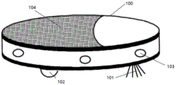
Fig. 1 is a schematic view of a sweeping robot in embodiment 1;
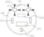
fig. 2 is a schematic bottom view of the sweeping robot in embodiment 1;
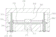
FIG. 3 is a schematic view of a cleaning mechanism in embodiment 1;
fig. 4 is a schematic view of the support plate in embodiment 1;
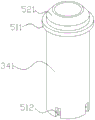
FIG. 5 is a schematic view of a rotary drum in embodiment 1;
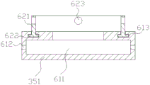
FIG. 6 is a schematic diagram of a spray block in example 1;
FIG. 7 is a schematic view of a brushing mechanism in embodiment 1;
fig. 8 is a schematic view of the hinge and drum structure in embodiment 1.
The names of the parts indicated by the numerical references in the drawings are as follows: 100. a robot body; 101. a cleaning mechanism; 102. a driving mechanism; 103. a heat radiation hole; 104. a cover plate; 211. a driving wheel; 212. a steering wheel; 221. a connecting rod; 222. a brush; 231. a dust collection port; 241. a brushing and sucking mechanism; 311. a first mounting cavity; 312. a second mounting cavity; 313. a groove; 321. a column; 322. a water mist channel; 331. a support plate; 341. a rotating cylinder; 351. a spray block; 361. a servo motor; 362. a first bevel gear; 371. a first cylinder; 411. a through hole; 412. a rotating groove; 511. a rotating ring; 512. a hinge groove; 521. a second bevel gear; 611. a cavity; 612. a fog outlet; 613. a first chute; 621. a slip ring; 622. a slide rail; 623. a spring mounting hole; 711. a third mounting cavity; 712. a fourth mounting cavity; 721. a second cylinder; 731. a second spring; 741. a pushing block; 742. a first inclined surface; 751. a sliding block; 752. a second inclined surface; 761. a connecting rod; 771. a hinge; 772. a roller; 773. a sponge layer; 811. a sliding block.
Detailed Description
For a further understanding of the present invention, the present invention will be described in detail with reference to the drawings and examples. It is to be understood that the examples are illustrative of the present invention and are not intended to be limiting.
Example 1
As shown in fig. 1 to 8, the present embodiment provides a floor sweeping robot comprising a robot body 100, the robot body 100 comprising a driving mechanism 102 and a cleaning mechanism 101, the driving mechanism 102 comprising a driving wheel 211 and a steering wheel 212 which are positioned at the lower end of the robot body 100 and driven by a motor; the cleaning mechanism 101 comprises first mounting cavities 311 which are symmetrically arranged and open towards the lower end of the robot body 100, the top walls of the first mounting cavities 311 are communicated through second mounting cavities 312, upright posts 321 are arranged in the first mounting cavities 311 along the extending direction of the first mounting cavities 311, and grooves 313 are formed in the lower side walls of the second mounting cavities 312; a supporting plate 331 positioned in the second installation cavity 312 is arranged between the stand columns 321, a through hole 411 is arranged on the supporting plate 331, the stand columns 321 penetrate through the through hole 411, a rotating groove 412 which is coaxial with the through hole 411 is arranged on the side wall of the through hole 411, a servo motor 361 is arranged on the upper plate surface of the supporting plate 331, a first bevel gear 362 is arranged on the rotating shaft of the servo motor 361, and the lower plate surface of the supporting plate 331 is connected with a first cylinder 371 positioned in the groove 313; the through hole 411 is rotationally provided with a cylindrical rotating cylinder 341, the stand column 321 passes through the rotating cylinder 341, the outer side wall of the rotating cylinder 341 is provided with a rotating ring 511 which can be positioned in the rotating groove 412, the upper end surface of the rotating cylinder 341 is provided with a second bevel gear 521 which is circular ring-shaped and meshed with the first bevel gear 362, the side surface of the rotating cylinder 341 and the bottom end are provided with a plurality of hinge grooves 512, the hinge grooves 512 are uniformly distributed in the circumferential direction of the rotating cylinder 341, a connecting rod 221 is hinged in the hinge groove 512, and the end part of the connecting rod 221 is connected with a brush 222 for brushing dust; the cleaning mechanism 101 further includes a dust suction port 231 at the lower end of the robot body 100 for sucking up dust swept up by the brush 222.
Through the arrangement of the driving mechanism 102 in the embodiment, the driving mechanism 102 can drive the robot body 100 to move, so as to automatically clean the ground, wherein the driving wheels 211 and the steering wheels 212 are arranged, so that the driving wheels 211 can move the robot body 100, and the steering wheels 212 can steer the robot body 100; the robot body 100 can clean dust on the ground by arranging the cleaning mechanism 101; the arrangement of the servo motor 361, the first bevel gear 362, the rotating cylinder 341 and the second bevel gear 521 enables the servo motor 361 to rotate to drive the first bevel gear 362 to rotate and further drive the rotating cylinder 341 to rotate; the arrangement of the hinge groove 512 and the connecting rod 221 enables the connecting rod 221 to be hinged in the hinge groove 512, so that the connecting rod 221 can be installed on the rotating cylinder 341, and the rotating cylinder 341 rotates to drive the connecting rod 221 to rotate, so that the brush 222 can sweep on the ground; wherein, the upright post 321, the support plate 331, the through hole 411, the rotating groove 412, the rotating ring 511 and the first cylinder 371 are arranged, the rotating cylinder 341 can rotate while the rotating cylinder 341 can be arranged on the support plate 331 through the matching of the rotating ring 511 and the rotating groove 412, when the first cylinder 371 drives the support plate 331 to move upwards, the rotating cylinder 341 moves upwards to drive the connecting rod 221 to ascend, so that the hairbrush 222 can be received in the robot body 100, and the hairbrush 222 of the sweeping robot can not adsorb sundries when the ground is wet; when the first cylinder 371 drives the support plate 331 to move downwards, the position of the connecting rod 221 is manually placed so that the servo motor 361 rotates to drive the brush 222 to brush the ground. According to the technical scheme, the brush 222 of the floor sweeping robot can sweep dust on the floor, meanwhile, the brush 222 can be received in the robot body 100, and impurities are prevented from being adsorbed on the brush 222 due to the fact that the floor sweeping is wet.
In the embodiment, a circular ring-shaped spraying block 351 is arranged at the bottom end of a stand column 321, a water mist channel 322 is arranged in the stand column 321, a cavity 611 communicated with the water mist channel 322 is arranged in the spraying block 351, a mist outlet 612 is arranged on the side wall of the cavity 611, a first chute 613 with a T-shaped cross section and coaxially arranged with the stand column 321 is arranged on the upper side surface of the spraying block 351, a circular ring-shaped sliding ring 621 is slidably arranged at the first chute 613, a sliding rail 622 matched with the first chute 613 is arranged at the bottom end of the sliding ring 621, a spring mounting hole 623 corresponding to the hinge groove 512 is arranged on the sliding ring 621, and a first spring connected with a corresponding connecting rod 221 is arranged in the spring mounting hole 623; an atomizing device for atomizing water and communicating with the mist passage 322 is provided in the robot body 100.
Through the arrangement of the atomizing device, the water mist channel 322, the atomizing block 351 and the mist outlet 612 in the embodiment, the atomizing device can atomize water, and the water mist is injected into the atomizing block 351 through the water mist channel 322 and is further discharged from the mist outlet 612, so that the dry cleaning ground is wetted, and the generation of dust during brushing of the hairbrush 222 is reduced; by the arrangement of the first sliding groove 613, the sliding ring 621 and the sliding rail 622, the sliding rail 622 is positioned in the first sliding groove 613, so that the sliding ring 621 can rotate along the first sliding groove 613, and the sliding ring 621 cannot be separated from the spraying block 351; wherein, the setting of spring mounting hole 623 and first spring for first spring provides elasticity and makes connecting rod 221 to the opening part circumference removal of first installation cavity 311, thereby makes connecting rod 221 strut around the opening part of first installation cavity 311 voluntarily when first cylinder 371 descends, need not manual the putting, simultaneously, the servo motor 361 of being convenient for rotates and drives the brush 222 and rotate cleans.
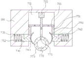
In this embodiment, the robot body 100 further includes a brushing mechanism 241, the brushing mechanism 241 includes a third mounting cavity 711 with an opening facing the lower end of the robot body 100, a second air cylinder 721 is fixedly disposed on a top wall of the third mounting cavity 711, a hinge member 771 is connected to a push rod of the second air cylinder 721, a roller 772 is hinged to the hinge member 771, and a sponge layer 773 is sleeved on an outer side of the roller 772.
By the arrangement of the brushing and sucking mechanism 241 in the embodiment, the robot body 100 can wipe the wet ground; the second air cylinder 721, the hinge 771 and the roller 772 are arranged, so that the second air cylinder 721 drives the hinge 771 to lift and further drives the roller 772 to extend out of and retract into the robot body 100, thereby facilitating the use of the roller 772; wherein, the setting of sponge layer 773 for sponge layer 773 absorbs subaerial water, accomplishes the wiping to the ground.
In this embodiment, the left and right side walls of the third installation cavity 711 are symmetrically provided with a fourth installation cavity 712 with an opening facing the third installation cavity 711, a push block 741 extending out of the fourth installation cavity 712 is arranged in the fourth installation cavity 712 through a second spring 731, an extrusion plate 743 for extruding the sponge layer 773 is connected to the end part of the push block 741, and a first inclined plane 742 is arranged on the upper side surface of the push block 741; a sliding block 751 is slidably arranged on the side wall of the third mounting cavity 711 and above the fourth mounting cavity 712 along the moving direction of the roller 772, a second inclined surface 752 for pushing the sliding block 741 out of the fourth mounting cavity 712 by being extruded by the first inclined surface 742 is arranged on the lower end surface of the sliding block 751, and the upper end parts of the sliding blocks 751 are hinged to one end of a connecting rod 761; the other ends of the links 761 are each hinged to the push rod of the second cylinder 721, and the middle portions of the links 761 are each hinged to the side wall of the third mounting chamber 711.
Through the arrangement of the pushing block 741 and the extrusion plate 743 in the embodiment, the pushing block 741 drives the extrusion plate 743 to extrude the sponge layer 773 on the roller 772, so that water absorbed by the sponge layer 773 is discharged out of the sponge layer 773, and the sponge layer 773 can wipe wet ground repeatedly; by arranging the connecting rod 761 and the sliding block 751, when the push rod of the second air cylinder 721 moves upwards, the connecting rod 761 is driven to move so as to drive the sliding block 751 to move downwards, and the second inclined surface 752 on the sliding block 751 presses the first inclined surface 742 on the pushing block 741, so that the pushing block 741 pushes the pressing plate 743 to press and dehydrate the sponge layer 773 on the roller 772 which rises along with the second air cylinder 721; wherein the second spring 731 is disposed such that when the push rod of the second air cylinder 721 moves downward, the second spring 731 provides an elastic force to pull the push block 741 to retract into the fourth installation cavity 712, the pressing plate 743 releases the pressing of the drum 772, and the drum 772 protrudes out of the robot body 100 to wipe the ground.
In this embodiment, the front and rear sidewalls of the third mounting chamber 711 are provided with a T-shaped second sliding groove along the moving direction of the drum 772, and the hinge 771 is provided with a slider 811 engaged with the second sliding groove.
By the arrangement of the second slide groove and the slider 811 in the present embodiment, the sliding of the slider 811 in the second slide groove restricts the moving direction of the hinge 771, thereby preventing the hinge 771 from rocking in the third mounting chamber 711.
In this embodiment, a cover plate 104 is hinged to the top end of the robot body 100.
Through the setting of apron 104 in this embodiment, make apron 104 can open and shut and then conveniently inhale the dust in the robot body 100 through dust absorption mouth 231 and obtain discharging to the use of robot of sweeping the floor is convenient for.
In this embodiment, the side wall of the robot body 100 is provided with a heat dissipation hole 103.
By the arrangement of the heat dissipation holes 103 in the embodiment, heat generated in the robot body 100 can be dissipated, so that the service life of the sweeping robot is prolonged.
When the sweeping robot of this embodiment is specifically used, according to the ground wetting condition, when the ground is wet, the first cylinder 371 is started to enable the brush 222 to be received in the robot body 100, the second cylinder 721 is started to enable the roller 772 to extend out of the robot body 100, the robot body 100 finishes wiping the wet ground under the action of the driving mechanism 102, when the wiping of the wet ground is finished, the second cylinder 721 is started to enable the roller 772 to retract into the robot body 100, at the moment, the sliding block 751 drives the pushing block 741 to enable the extrusion plate 743 to extrude and dehydrate the sponge layer 773 on the roller 772, when the ground is dry, the first cylinder 371 enables the brush 222 in the robot body 100 to extend, the servo motor 361 is started to drive the brush 222 to brush, meanwhile, the atomization device in the robot body 100 discharges generated water mist from the water mist channel 322 to the spray block 351, and the mist outlet holes 612 spray the ground to wet ground, and dust generation is reduced.
In summary, the foregoing description is only of the preferred embodiments of the present invention, and all equivalent changes and modifications made in accordance with the claims should be construed to fall within the scope of the invention.
Claims (7)
1. The utility model provides a robot sweeps floor which characterized in that: comprises a robot body (100), wherein the robot body (100) comprises a driving mechanism (102) and a cleaning mechanism (101), and the driving mechanism (102) comprises a driving wheel (211) and a steering wheel (212) which are positioned at the lower end part of the robot body (100) and driven by a motor; the cleaning mechanism (101) comprises first mounting cavities (311) which are symmetrically arranged and are opened towards the lower end of the robot body (100), the top wall of each first mounting cavity (311) is communicated through a second mounting cavity (312), upright posts (321) are arranged in each first mounting cavity (311) along the extending direction of each first mounting cavity (311), and grooves (313) are formed in the lower side walls of the second mounting cavities (312); a supporting plate (331) positioned in the second mounting cavity (312) is arranged between the upright posts (321), a through hole (411) is formed in the supporting plate (331), the upright posts (321) penetrate through the through hole (411), a rotating groove (412) coaxially arranged with the through hole (411) is formed in the side wall of the through hole (411), a servo motor (361) is arranged on the upper plate surface of the supporting plate (331), a first bevel gear (362) is arranged on the rotating shaft of the servo motor (361), and the lower plate surface of the supporting plate (331) is connected with a first cylinder (371) positioned in the groove (313); the rotary dust collector comprises a rotary cylinder (341) which is cylindrical in shape and is arranged at the position of a through hole (411), an upright post (321) penetrates through the rotary cylinder (341), a rotary ring (511) which can be positioned in a rotary groove (412) is arranged on the outer side wall of the rotary cylinder (341), a second bevel gear (521) which is circular ring-shaped and meshed with a first bevel gear (362) is arranged on the upper end face of the rotary cylinder (341), a plurality of hinge grooves (512) are formed in the side face of the rotary cylinder (341) and are positioned at the bottom end of the rotary cylinder, the hinge grooves (512) are uniformly distributed in the circumferential direction of the rotary cylinder (341), a connecting rod (221) is hinged in the hinge grooves (512), and a brush (222) for brushing dust is connected to the end part of the connecting rod (221); the cleaning mechanism (101) further comprises a dust collection opening (231) positioned at the lower end of the robot body (100) and used for absorbing dust swept by the brush (222);
the bottom end of the upright post (321) is provided with a circular spray block (351), a water mist channel (322) is arranged in the upright post (321), a cavity (611) communicated with the water mist channel (322) is arranged in the spray block (351), and a mist outlet (612) for wetting the ground is arranged on the side wall of the cavity (611); an atomization device which is used for atomizing water and is communicated with a water mist channel (322) is arranged in the robot body (100);
the robot body (100) further comprises a brushing and sucking mechanism (241) which enables the robot body (100) to wipe the wet ground, the brushing and sucking mechanism (241) comprises a roller (772), and a sponge layer (773) is sleeved on the outer side of the roller (772).
2. A sweeping robot according to claim 1, wherein: the upper side of spray piece (351) is equipped with the cross-section and is T and with the coaxial first spout (613) that set up of stand (321), and first spout (613) department slides and is equipped with and is annular sliding ring (621), and the bottom of sliding ring (621) is equipped with slide rail (622) with first spout (613) matched with, is equipped with on sliding ring (621) with hinge groove (512) corresponding spring mounting hole (623), install the first spring that links to each other with corresponding connecting rod (221) in spring mounting hole (623).
3. A sweeping robot according to claim 1, wherein: the brushing mechanism (241) comprises a third mounting cavity (711) with an opening facing the lower end of the robot body (100), a second air cylinder (721) is fixedly arranged on the top wall of the third mounting cavity (711), a hinge piece (771) is connected to a push rod of the second air cylinder (721), and a roller (772) is hinged to the hinge piece (771).
4. A sweeping robot according to claim 3, wherein: the left side wall and the right side wall of the third installation cavity (711) are symmetrically provided with a fourth installation cavity (712) with an opening facing the third installation cavity (711), a push block (741) extending out of the fourth installation cavity (712) is arranged in the fourth installation cavity (712) through a second spring (731), the end part of the push block (741) is connected with an extrusion plate (743) for extruding a sponge layer (773), and the upper side surface of the push block (741) is provided with a first inclined surface (742); a sliding block (751) is arranged on the side wall of the third mounting cavity (711) and above the fourth mounting cavity (712) in a sliding manner along the moving direction of the roller (772), a second inclined surface (752) for extruding the pushing block (741) out of the fourth mounting cavity (712) with the first inclined surface (742) is arranged on the lower end surface of the sliding block (751), and the upper end parts of the sliding blocks (751) are hinged to one end of a connecting rod (761); the other ends of the connecting rods (761) are hinged on the push rod of the second air cylinder (721), and the middle parts of the connecting rods (761) are hinged on the side wall of the third mounting cavity (711).
5. The robot cleaner of claim 4, wherein: the front and rear side walls of the third installation cavity (711) are provided with T-shaped second sliding grooves along the moving direction of the roller (772), and the hinge piece (771) is provided with sliding blocks (811) matched with the second sliding grooves.
6. The robot cleaner of claim 5, wherein: a cover plate (104) is hinged on the top end of the robot body (100).
7. The robot cleaner of claim 6, wherein: the side wall of the robot body (100) is provided with a heat radiation hole (103).
Priority Applications (1)
| Application Number | Priority Date | Filing Date | Title |
|---|---|---|---|
| CN201910502414.7A CN110384441B (en) | 2019-06-11 | 2019-06-11 | Sweeping robot |
Applications Claiming Priority (1)
| Application Number | Priority Date | Filing Date | Title |
|---|---|---|---|
| CN201910502414.7A CN110384441B (en) | 2019-06-11 | 2019-06-11 | Sweeping robot |
Publications (2)
| Publication Number | Publication Date |
|---|---|
| CN110384441A CN110384441A (en) | 2019-10-29 |
| CN110384441B true CN110384441B (en) | 2023-06-06 |
Family
ID=68285537
Family Applications (1)
| Application Number | Title | Priority Date | Filing Date |
|---|---|---|---|
| CN201910502414.7A Active CN110384441B (en) | 2019-06-11 | 2019-06-11 | Sweeping robot |
Country Status (1)
| Country | Link |
|---|---|
| CN (1) | CN110384441B (en) |
Families Citing this family (1)
| Publication number | Priority date | Publication date | Assignee | Title |
|---|---|---|---|---|
| CN111283699B (en) * | 2020-03-27 | 2024-10-18 | 广州美术学院 | Household service robot |
Citations (7)
| Publication number | Priority date | Publication date | Assignee | Title |
|---|---|---|---|---|
| JP2011012462A (en) * | 2009-07-02 | 2011-01-20 | Fukumoto Body:Kk | Self-traveling cleaning machine |
| CN106852669A (en) * | 2016-11-14 | 2017-06-16 | 钟玲珑 | Suitable for the Intelligent robot for sweeping floor on out-of-flatness ground |
| CN108577685A (en) * | 2018-05-18 | 2018-09-28 | 江苏昊科汽车空调有限公司 | A kind of dust cleaning plant convenient for sweeping robot |
| CN108903817A (en) * | 2018-06-28 | 2018-11-30 | 廖志敏 | Floor brush for floor sweeping robot |
| CN109157165A (en) * | 2018-09-14 | 2019-01-08 | 合肥梦龙电子科技有限公司 | A kind of domestic intelligent cleaning vehicle |
| CN109567683A (en) * | 2019-01-31 | 2019-04-05 | 任飞 | A kind of intelligent sweeping robot |
| CN211022465U (en) * | 2019-06-11 | 2020-07-17 | 皖西学院 | Floor sweeping robot |
-
2019
- 2019-06-11 CN CN201910502414.7A patent/CN110384441B/en active Active
Patent Citations (7)
| Publication number | Priority date | Publication date | Assignee | Title |
|---|---|---|---|---|
| JP2011012462A (en) * | 2009-07-02 | 2011-01-20 | Fukumoto Body:Kk | Self-traveling cleaning machine |
| CN106852669A (en) * | 2016-11-14 | 2017-06-16 | 钟玲珑 | Suitable for the Intelligent robot for sweeping floor on out-of-flatness ground |
| CN108577685A (en) * | 2018-05-18 | 2018-09-28 | 江苏昊科汽车空调有限公司 | A kind of dust cleaning plant convenient for sweeping robot |
| CN108903817A (en) * | 2018-06-28 | 2018-11-30 | 廖志敏 | Floor brush for floor sweeping robot |
| CN109157165A (en) * | 2018-09-14 | 2019-01-08 | 合肥梦龙电子科技有限公司 | A kind of domestic intelligent cleaning vehicle |
| CN109567683A (en) * | 2019-01-31 | 2019-04-05 | 任飞 | A kind of intelligent sweeping robot |
| CN211022465U (en) * | 2019-06-11 | 2020-07-17 | 皖西学院 | Floor sweeping robot |
Also Published As
| Publication number | Publication date |
|---|---|
| CN110384441A (en) | 2019-10-29 |
Similar Documents
| Publication | Publication Date | Title |
|---|---|---|
| CN108670129B (en) | Intelligent floor sweeping robot based on Internet of things and implementation method thereof | |
| CN208837816U (en) | Bulky grain dust-absorbing floor brush and its cleaning machine | |
| CN211299811U (en) | Cleaning and floor sweeping robot device | |
| CN110384441B (en) | Sweeping robot | |
| CN110899196B (en) | Fountain herbal pieces-belt cleaning device | |
| CN208301598U (en) | A kind of electric sweeper | |
| CN211022465U (en) | Floor sweeping robot | |
| CN214906422U (en) | Self-cleaning floor sweeping robot | |
| CN211460056U (en) | Cleaning device with comb-tooth pipe | |
| WO2018210003A1 (en) | Automatic window cleaning robot | |
| CN112982250A (en) | Road cleaning equipment for energy-saving environmental sanitation workers | |
| CN113116226A (en) | Cleaning device with comb-tooth pipe | |
| CN208551664U (en) | A kind of the Ca Di mechanism and sweeper of New Sweeping Floor Machine | |
| CN213405900U (en) | Robot of sweeping floor with drag ground function | |
| CN221013143U (en) | Intelligent floor sweeping robot | |
| CN220757310U (en) | A removable dish of sweeping floor for sweeping floor machine | |
| CN218960636U (en) | Floor sweeping machine | |
| CN214972424U (en) | Filter screen cleaning equipment for central air conditioning maintenance | |
| CN220512786U (en) | Cleaning structure of sweeping robot | |
| CN220192897U (en) | Quick cleaner for elevator car | |
| CN211383830U (en) | Spray drying tower with purging device for graphene | |
| CN219973050U (en) | Automatic cleaning machine for ground sand residue | |
| CN221242709U (en) | Central rolling brush of sweeping robot | |
| CN219092882U (en) | Carousel smoking machine carousel apron cleaning machine | |
| CN221453523U (en) | Pretreatment device for flat cable production |
Legal Events
| Date | Code | Title | Description |
|---|---|---|---|
| PB01 | Publication | ||
| PB01 | Publication | ||
| SE01 | Entry into force of request for substantive examination | ||
| SE01 | Entry into force of request for substantive examination | ||
| GR01 | Patent grant | ||
| GR01 | Patent grant |