Detailed Description
The following is a description of versions of a tuft picker including a tuft picker adapted to provide standard and non-standard filaments, such as shaped filaments, in particular X-shaped filaments, tapered filaments or ultra-thin filaments for brush production, in particular for toothbrush production. The description further discloses a method of using the tuft picker, which can be used for producing (dental) brushes and the produced toothbrushes themselves. The description is to be construed as exemplary only and does not describe every possible embodiment since describing every possible embodiment would be impractical, if not impossible, and it will be understood that any feature, characteristic, structure, component, step or methodology described herein can be deleted, combined with or substituted for, in whole or in part, any other feature, characteristic, structure, component, product step or methodology described herein. Furthermore, individual features or (sub-) combinations of features may have inventive properties independently of the feature combinations provided in the claims, the respective parts of the description or the drawings.
The unit "cm" as used herein refers to centimeters. The unit "mm" as used herein refers to millimeters. The units "μm" or "microns" as used herein refer to microns. "mil" as used herein means one thousandth of an inch.
As used herein, the word "about" refers to +/-10%.
As used herein, the word "comprise", and variations thereof, is intended to be non-limiting, such that recitation of items in a list is not to the exclusion of other like items that may also be useful in the materials, devices, and methods of this invention. The term includes "consisting of and" consisting essentially of.
As used herein, the word "comprise" and variations thereof is intended to be non-limiting, such that recitation of items in a list is not to the exclusion of other like items that may also be useful in the materials, devices, and methods of this invention.
As used herein, the words "preferred," "preferably," and variations thereof such as "particularly" and "specifically" refer to embodiments of the invention that are capable of providing specific benefits under specific circumstances. However, other embodiments may also be preferred under the same or other circumstances. Furthermore, the recitation of one or more preferred embodiments does not imply that other embodiments are not useful, and is not intended to exclude other embodiments from the scope of the invention.
The invention provides a tuft picker for a brush making machine. The tuft picker is capable of picking a predefined number of filaments from filament containers which provide a supply of loose filaments in parallel condition to each other. The circumference of the loose filaments may be substantially circular, or the circumference may include at least one recess or may vary along the length axis of the filament. As understood herein, a "filament container" shall include any geometric shaped container suitable for storing loose filaments in parallel. A plurality of filaments are arranged in a filament receptacle along their long axes. This means that the long axis of each filament element is arranged parallel to the adjacent filaments. The filament container has one open side or there is an opening in one side wall. At this opening, the filaments are exposed to the environment, in particular to a tuft picker as disclosed herein and can be removed from the filament container by said tuft picker. Opposite the opening of the filament container, a plunger or the like can be arranged, which continuously presses the loose filaments towards the open side of the filament container.
The tufts may be monofilaments, for example made of a plastic material. Suitable plastic materials for the filaments may be Polyamides (PA), in particular nylon, polybutylene terephthalate (PBT), polyethylene terephthalate (PET) or mixtures thereof. In addition, the filament material may contain additives such as abrasives, color pigments, fragrances, and the like. For example, abrasives such as kaolin may be added and/or filaments colored at the outer surface in order to achieve an indicating material. The coloration on the exterior of the material slowly fades away during use to indicate the extent to which the filaments are worn. Suitable additives for the tufted filament are, for example, ultraviolet fluorescent (UV) whiteners, signaling substances, such as indicator color pigments and/or abrasives. The filaments may have a diameter in the range of about 0.1mm to about 0.5mm, specifically in the range of about 0.15mm to about 0.4mm, more specifically in the range of about 0.18mm to about 0.35mm, or any other range of values which is narrower and falls within the broader range of values set forth above, as if each of these narrower ranges of values were explicitly set forth herein.
Furthermore, for standard filaments having the diameters given above, ultra thin filaments are used in the toothbrush. Ultra-thin filaments have smaller diameters than standard filaments and can act like dental floss during normal brushing. The ultrathin filaments can have a diameter in the range of about 0.05mm to about 0.15mm, specifically in the range of about 0.07mm to about 0.13mm, more specifically in the range of about 0.09mm to about 0.11mm, or in any other numerical range that is narrower and falls within the broader numerical range set forth above, as if each of these narrower numerical ranges were expressly set forth herein. The production tolerance of the filament diameter was 10%.
In addition to filaments having a substantially constant diameter, filaments having a diameter that decreases toward the ends may also be used. These types of tapered filaments are based on standard diameter filaments whose ends are chemically tapered. Suitable tapered filaments are provided by, for example, BBC corporation of korea.
Further, the filaments may be used in toothbrushes comprising an irregular diameter (i.e. comprising at least one recess). As understood herein, "recess" in the filament circumference, diameter, and/or volume shall mean any depression, cavity, slot, or other geometric recess that modifies the filament volume. A filament having at least one recess on its circumference may have one or more recesses along the circumference of the filament. A suitable example of a filament having at least one recess is an X-shaped filament. The X-shaped filament has four valleys and two lines of reflective symmetry, each line of reflective symmetry passing through two valleys opposite to each other. Furthermore, all four recesses may be identical. The included angle of the X-shaped filaments may be in the range of about 40 ° to about 160 °.
The length of the filaments depends on the intended use. In general, the filaments may have any suitable length for shipping, such as about 1300mm, and then cut into segments of the desired length. The length of the filaments in the toothbrush affects the bending force required to bend the filaments. Thus, the length of the filaments can be used to achieve different stiffness of the filaments in the tufted pattern. Typical lengths of filaments for brushes, particularly toothbrushes, can range from about 5mm to about 18mm, particularly from about 6mm to about 15mm, more particularly from about 7mm to about 13mm, or any other range of values which are narrower and fall within the broader ranges of values noted above, as if each of these narrower ranges of values were explicitly set forth herein. The filaments to be picked by the tuft picker as disclosed herein may be mounted to the brush by an anchor line. These filaments typically have a doubled length compared to filaments mounted to the brush by anchorless techniques. In addition, the filaments may be longer than the final filament length in the resulting brush head so that after they are sorted, the filaments may be cut to different specific final lengths. The length of the filaments to be sorted may be longer than the length of the final filaments by an amount in the range of about 0.5mm to about 5mm, specifically in the range of about 1mm to about 4mm, more specifically in the range of about 1.5mm to about 3mm, or any other range of values that is narrower and falls within the broader range of values described above, as if each of these narrower ranges of values were expressly set forth herein. In particular, if the brush is manufactured by an anchoring technique, all the filaments are tufted into the brush head first, and then the filaments are cut to their final length. After cutting, the cutting end is rounded to remove a sharp end that may injure the gums of the brush user. The rounding process comprises several successive polishing steps, preferably with reduced abrasiveness. If tapered filaments or ultra-thin filaments are used, the standard filaments are cut to length and first are inverted round before the tapered or ultra-thin filaments can be mounted on the brush so as not to alter the ends of the tapered filaments or ultra-thin filaments. Alternatively, the tapered or ultra-thin filaments may be bent during cutting and rounding of the standard filaments.
The filaments in the brush head, and in particular the toothbrush head, are grouped into filament tufts. A suitable number of filaments to form a filament tuft may be in the range of, for example, about 10 to about 80 filaments, or in the range of about 15 to about 60 filaments, or in the range of about 20 to about 50 filaments, or in any other numerical range that is narrower and falls within the broader numerical range set forth above, as if such narrower numerical ranges were expressly set forth herein. The predefined number of filaments that should form one filament tuft is separated from the filament container mechanically (i.e. by the picking process), in particular by the picking process as disclosed herein. As understood herein, "picking" shall mean continuously pushing filaments perpendicular to their length axis from a filament container in the direction of a tuft picker as disclosed herein, wherein the tuft picker comprises at least one picker eye capable of accepting a predefined number of filaments. The picked quantity of filaments (referred to as a filament tuft) is then transferred to a brush making machine and the filaments are installed into the brush head.
A "tuft picker" as disclosed herein comprises at least two parts of equal shape spaced apart by a distance. The two portions each comprise a working surface comprising at least one picker eye. The at least one picker eye is a recess along the working surface, thus comprising a depth, a width along the depth and an opening in/at the working surface. The first and second portions of the tuft picker are arranged with respect to each other such that the working surface is positioned on a common shaping line and the at least one picker eye is arranged at the same location at the working surface. Thereby, a picker eye volume is formed comprising picker eyes in a first or upper part of the tuft picker, picker eyes in a second or lower part of the tuft picker and a gap there between. Furthermore, the tuft picker may comprise one or more additional portions positioned between the first upper portion and the second lower portion of the tuft picker. The additional portions interposed between the first upper portion and the second lower portion each include identical picker eyes positioned at the same positions from each other. If an additional section is arranged between the first upper section and the second lower section, the clearance can be increased without running the risk of the filaments bending or breaking inside the eye volume of the picker. The number of additional sections is not limited and is selected according to the size of the picker eye volume. During the picking process, the picker eye volume may be filled with filaments, wherein one end of a filament will protrude from the picker eye in the first section of the tuft picker and the other filament end will protrude from the picker eye in the second section of the tuft picker.
The distance between the first and second portions of the tuft picker is constant and the cover tool is positioned in the gap. If one or more additional portions of the tuft picker are positioned between the first upper portion and the second lower portion of the tuft picker, there is more than one gap in which the covering tool can be positioned. Each covering tool includes a hook connected to the body by a spacer. The hook of the covering tool comprises a first surface and a second surface, wherein the form of the first surface corresponds to the form of the working surface at the opening of the picker eye. Furthermore, the main body of the covering tool is movably arranged between the first and second portions and optionally any additional portion of the tuft picker, in particular the covering tool is movable relative to the picker eye. In the first position of the covering means, the hook is positioned outside of a picker eye volume formed by the two or more picker eyes and the void. In the second position, the covering tool is positioned such that the hook limits clearance of the picker eye volume on the forming wire of the work surface. This means that the picker eyes in the first and second sections of the tuft picker are still open, although the picker eye volume is closed on the shaping line of the working surface (i.e. with respect to the outside of the tuft picker). If more than one picker eye is arranged at each working surface of the tuft picker, the one or more draping tools may also be designed to successively close the resulting more than one picker eye volume.
The body of the overlay tool is movable relative to the picker eye and picker eye volume, respectively. Further, the body may be positioned partially inside the picker eye volume in the first position of the covering tool and less partially or completely outside the picker eye volume in the second position of the covering tool. This means that the body of the covering means covers a part of the picker eye volume in the first position of the covering means, so that this part cannot be filled with filaments during picking. In particular, the portion of the body may cover a base of the picker eye volume. During the movement of the covering tool from its first position to its second position, the main body will be removed from the picker eye volume, thereby at least partially freeing the space previously covered. This means that filaments positioned inside the picker eye and the picker eye volume can be transferred deeper into the picker eye and the picker eye volume during the movement of the covering means from its first position to its second position. Parallel to the movement of the body out of the picker eye and the picker eye volume, the hook moves from its position outside the shaping line of the opening of the picker eye into the shaping line of the opening in the working surface. Thus, the volume covered by the portion of the body in the first position of the covering tool is the same as or less than the volume covered by the hook in the second position of the covering tool. Thus, in both the first and second positions of the covering means, the volume of the picker eye volume which can be filled with filaments is the same, or the volume of the picker eye volume is larger in the second position of the covering means. If the volume of the picker eye volume is greater in the second position, the increased volume is such that the filaments remain securely held in the picker eye volume, but the slightly increased volume simplifies the deeper transport of the filaments inside the picker eye volume.
The contour of the hook covering the tool is adapted to transfer objects positioned inside the picker eye volume deeper into said volume. In particular, the second surface of the hook is adapted to transfer objects positioned inside the picker eye volume deeper into said picker eye volume, thereby being adapted to transfer objects positioned inside the picker eye volume outside the forming lines of the openings in the working surfaces of the first and second portions of the tuft picker. For example, the hook may be sickle-shaped. Additionally or alternatively, the ends of the hooks may be rounded so that the ends of the hooks do not grip or damage the filaments being picked. Additionally or alternatively, the second surface of the hook (which is the surface located inside the picker eye volume in the second position of the covering tool) may be chamfered from an end, preferably a rounded end, of the hook to a base of the hook, which is connected to the shim of the covering tool. The width of the hook may increase from the end, preferably the rounded end, to the base of the hook where it is connected to the spacer. Suitable widths for the hooks can be in the following ranges: from about 0.01mm to about 0.1mm at the ends to about 0.1mm to about 5mm at the pads, preferably from about 0.01mm to about 0.05mm at the ends to 0.2mm to 1mm at the pads, or any other range of values that is narrower and falls within the broader range of values set forth above, as if each of these narrower ranges of values were explicitly set forth herein.
Additionally or alternatively, the picker eyes may mainly have any geometrical form as long as the picker eyes in the first section of the tuft picker and the corresponding picker eyes in the second section of the tuft picker are identical. The form of the picker eye may help capture filaments to be picked inside the picker eye. The inner surface of the picker eye may be regular or irregular. An irregular inner surface of the picker eye may be preferred because any movement of filaments in the picker eye may be reduced, thereby making it easier for the picked filaments to be stored inside the picker eye. Suitable forms of the picker eye are, for example, circular, elliptical, or combinations thereof. In particular, the picker eye may be elliptical, with the depth of the picker eye being greater than the width of the picker eye. The oblong shape may also assist in picking filaments having at least one recess to retain the filaments in the picker eye during movement of the tuft picker. For example, the picker eye may be oval shaped, including a depth in the range of about 0.5mm to about 5mm and a width in the range of about 0.1mm to about 3mm, preferably a depth in the range of about 1mm to about 4mm and a width in the range of about 0.5mm to about 1.5mm, or a depth and a width in any other range of values that are narrower and fall within the broader range of values noted above, as if each of these narrower ranges of values were expressly set forth herein. Alternatively, the picker eye may be elliptical, with the width of the picker eye being greater than the depth of the picker eye. For example, the picker eye may be oval, including a width in the range of about 1mm to about 8mm and a depth in the range of about 0.4mm to about 4mm, preferably a width in the range of about 1.5mm to about 5mm and a depth in the range of about 0.5mm to about 3 mm. A picker eye of the type described is particularly useful for tuft pickers comprising a straight working surface.
Additionally or alternatively, the width of the picker eye may vary along the depth of the picker eye. This means that the width at the base of the picker eye may be greater than the width of the opening of the picker eye. The variation in width along the picker eye depth may help to retain the filaments in the picker eye during movement of the tuft picker. Additionally or alternatively, the depth of the picker eye may be adjusted between two consecutively performed work strokes or a predefined number of performed work strokes. By varying the depth of the picker eye, the size of the picker eye and the picker eye volume changes. The size of the picker eye and the picker eye volume corresponds to the predefined number of filaments picked to form one filament tuft after picking. This means that if the size of the picker eye and picker eye volume, respectively, is changed, different filament tufts can be picked with one tuft picker.
The opening of the picker eye may be reduced by two projections compared to the width of the picker eye itself. The top of the projection may be positioned in the working surface of the tuft picker such that the top of the projection may assist in separating filaments from the filament receptacle and may build a barrier to retain filaments that have been picked in the picker eye. Suitable projections limit the opening to a range of about 0.025mm to about 0.35mm, preferably about 0.5mm to about 0.3mm, more preferably 0.10mm to about 0.25mm, or any other numerical range that is narrower and falls within the broader numerical range set forth above, as if such narrower numerical ranges were expressly set forth herein. This means that the opening of the picker eye is smaller than the width of the picker eye outside the shaping line of the working surface, i.e. the width is reduced by the size of the projection. In particular, the picker eye may preferably comprise one projection at the side of the opening into the opening, wherein the end of the hook is positioned in the second position covering the tool, i.e. in the position when the end of the hook closes the picker eye opening. If the picker eye includes a protrusion at the side, the end of the hook may correspond to the form of the at least one protrusion so as to securely and firmly close the opening of the picker eye. In particular, the end of the hook may comprise the negative and/or the opposite form of said at least one protrusion. In particular, the projections are designed such that filaments separated from the filament receptacle are automatically transferred deeper into the volume of the picker eye.
The working surface is profiled to be movable during a working stroke past the open side of the filament container. As understood herein, a "working stroke" is any movement of the tuft picker that passes along the loose filaments in the filament container through the opening of the picker eye, wherein the filaments are transferred into the picker eye for eventual removal from the filament container. The profile of the working surface of the tuft picker may be straight or circular. This means that the working stroke may be a linear movement or a circular movement, depending on the contour of the tuft picker. Circular tuft pickers are commonly used in the prior art, but linear tuft pickers may also be adapted in combination with the picker eye and the covering tool as disclosed herein. If the tuft picker is a circular arc, the circular arc preferably comprises a curvature/diameter in the range of about 20mm to about 200mm, more preferably in the range of about 40mm to about 100mm, or in any other numerical range that is narrower and falls within the broader numerical ranges set forth above, as if such narrower numerical ranges were expressly set forth herein.
During its movement, the tuft picker may oscillate along a predefined pattern. For example, the linear tuft picker oscillates along a straight line and the curved tuft picker oscillates along a portion of an arc of a circle. Thereby, the tuft picker swings from the starting position to the reversal point. During the movement of the tuft picker, the covering tool is transferred from its first position (i.e. the open position) to its second position (i.e. the closed position). In particular, the movement of the covering tool is faster than the movement of the tuft picker, so that the covering tool reaches its second position before the tuft picker reaches the reversal point. This means that the opening of the picker eye is closed by the hook of the covering tool before the tuft picker reaches the reversal point of its movement. Preferably, the covering tool is transferred from its first position to its second position close to reaching the reversal point, since the movement of the tuft picker is minimal close to the reversal point. During the movement of the tuft picker back to its starting position, the covering tool can stay in its second position, so that the opening of the picker eye is closed during said movement. As soon as the tuft picker passes loose filaments during its movement back or has reached its starting position again, the covering tool can be moved back into its first position, so that the opening of the picker eye is opened again. The filaments may be removed from the picker eye after the first and/or second movement of the tuft picker.
Alternatively, the movement of the tuft picker may be unidirectional and continuous. For example, the tuft picker may be continuously moved in rotation. Suitable tuft pickers for the rotary movement are circular arcs, circles or partial circles. This rotational movement may be combined with more than one picker eye in order to increase the picking efficiency of the tuft picker. For example, picker eyes having different sizes may be arranged at one tuft picker, so that different filament tufts may be picked with one tuft picker. Additionally or alternatively, the tuft picker may comprise picker eyes distributed over the entire working surface, or the picker eyes may be grouped. The arrangement of more than one picker eye on the tuft picker may be adapted, for example, to a filament processing tool.
A straight tuft picker with a straight working surface may also be combined with more than one picker eye per tuft picker, wherein the picker eyes may be identical to or different from each other. The linear movement of the linear tuft picker is usually an oscillating movement, wherein the two directions of movement can represent the working stroke, i.e. the picking of the filaments from the filament container. If the tuft picker picks filaments in both directions, the picker eyes will be emptied at both sides of the filament container by suitable filament processing tools. Alternatively, only one direction of the linear movement may represent a working stroke, and the picker eye may pass the filament container and be closed in the reverse direction covering the tool, wherein the picker eye is still filled with filament or has been emptied.
Additionally or alternatively, the present disclosure further provides a method of providing filament tufts for use in brush manufacturing production, in particular toothbrush manufacturing production. The filament tufts comprise a predefined number of filaments. As understood herein, "a predefined number of filaments" means the number set by the size of the picker eye of the tuft picker as disclosed herein and used in the picking device. The predefined number may vary by about 25% above or below the set number in terms of the number of filaments selected and sorted. The method comprises using at least one tuft picker, preferably as disclosed herein, and further comprising laterally separating the filaments from a quantity of loose fibers to form filament tufts. The filaments to be sorted include standard and non-standard filaments, such as ultra-thin filaments or tapered filaments, or the filaments may include indentations, such as X-shaped filaments.
The method may include providing a filament in a filament container, wherein the filament is continuously displaced against an open side of the filament container. The opening of the at least one picker eye volume then passes along the open side of the filament container in order to transfer the filaments from the container into the picker eye. The filament positioned in the opening of the picker eye volume is then removed from the opening by sliding the hook of the covering tool into the opening. The filaments are thereby securely and firmly stored inside the picker eye volume and can be easily transferred for further processing. Accordingly, the method further comprises the step of transferring the filaments positioned in the closed picker eye volume to a removal device that removes the filaments from the picker eye volume for further processing. By sliding the hook of the covering tool out of the opening of the picker eye volume, the covering tool is opened just before it reaches the removal device. In parallel with the hooks sliding into and out of the opening of the picker eye volume, a portion of the body covering the tool slides out and into the picker eye volume. This means that in the open position of the hook a part of the body covering the tool is positioned at the base of the picker eye volume and when the hook is slid to its closed position, said part is removed from the picker eye volume. If the hook slides back to its open position, a portion of the main part of the body covering the tool is again moved into the base of the picker eye volume. Since the volume covered by this part of the body and by the hook is the same, the free space in the picker eye that can be filled with filaments is also the same, irrespective of the position of the covering tool. The picked filament is thus more or less clamped into the picker eye by the continuous clamping force. Alternatively, the volume covered by the main part of the body of the covering tool is larger than the volume covered by the hooks, so that the picker eye volume is slightly increased by moving the covering tool from its first position to its second position. The slightly increased picker eye volume makes it easier to remove filaments from the opening of the picker eye. The increase in picker eye volume will be small enough to hold the filaments firmly in the picker eye volume.
Additionally or alternatively, the present disclosure further provides a brush, in particular a toothbrush, comprising at least one filament tuft comprising at least one non-standard filament, for example a filament whose circumference comprises at least one recess, such as an X-shaped filament or a tapered filament or an ultra thin filament. The brush is manufactured using the method and/or tuft picker as disclosed herein. Preferably, the brush and/or toothbrush produced comprises at least one filament tuft comprising X-shaped filaments.
A detailed description of several exemplary embodiments will be given below. It should be noted that all of the features described in this disclosure, whether they are disclosed in the more general embodiments described above or in the exemplary embodiments of the devices described below, or even in the context of specific embodiments, may of course be stated in the context of a single feature disclosed as being combinable with all other disclosed features, provided that this would not contradict the spirit and scope of the disclosure. In particular, all features disclosed for any one of the devices or parts thereof may also be combined with and/or applied to other parts of the device or parts thereof (if applicable).
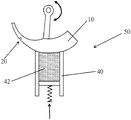
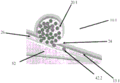
Fig. 1 shows a schematic view of a tuft picking device 50 for fixing filament tufts into a brush, in particular to a brush making machine in a toothbrush. The tuft picking device 50 comprises at least a tuft picker 10 and a filament container 40. Other components that may belong to the tuft picking device 50 are not shown to facilitate fig. 1. The filament container 40 is adapted to hold a plurality of loose filaments 42 in a parallel state with respect to each other. This means that the filaments 42 are positioned to have parallel major axes in the filament receptacle 40, with the major axes of the filaments 42 being parallel to the side walls of the filament receptacle 40. The filaments 42 may be, for example, monofilaments made of a plastic material such as Polyamide (PA), in particular PA 6.10 or PA 6.13. The filaments may have a diameter in the range of about 0.1mm to about 0.5mm and/or the filaments may be cut into segments having a length in the range of about 11mm to about 46 mm.
The filament container 40 can be of any geometry as long as the filaments 42 can be stored in the filament container 40. For example, filament container 40 includes two immovable sidewalls: a movable side wall and an open side. The movable side wall is positioned opposite the open side and moves in a direction of the open side, thereby moving the plurality of filaments 42 stored in the filament container 40 in the same direction. At the open side, the filaments 42 are in contact with the tuft picker 10. The tuft picker 10 comprises at least one picker eye 20 adapted to remove the filaments 42 from the filament container 40. The tuft picker 10 is attached to the tuft picking device 50 such that the tuft picker 10 is movable. The surface profile of the tuft picker 10 shown in fig. 1 is a circular arc and the movement of the tuft picker 10 is also a circular movement. The working stroke of the movement of the tuft picker 10, which means that the picker eye 20 is in contact with the thread 42 positioned in the thread receptacle 40, is also a circular movement, in particular an oscillating movement. Preferably, the reversal point of the tuft picker 10 is positioned at the open side of the filament container 40. This means that the picker eye 20 can be moved, for example, up to the middle of the open side of the filament container 40, filled with filaments 42 and removed to a position outside the filament container 40 (as shown in fig. 1). In a position outside of the filament container 40, the filaments 42 may then be removed from the picker eye 20 for mounting to the brush.
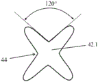
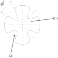
Fig. 2A and 2B each show a schematic view of a filament 42.1 comprising four recesses 44 on its circumference. The four recesses 44 are regularly arranged around the circumference of the filament 42.1, forming an X-shaped filament. Different forms and dimensions of the recess are possible. The included angle of each valley 44 of the X-shaped filaments 42.1 may be in the range of about 40 ° to about 160 °. The included angle of the illustrated recess 44 is about 120 ° in fig. 2A and about 40 ° in fig. 2B. The maximum dimension of the filament 42.1 may be in the range of about 0.1mm to about 0.5 mm. The depth of the recess 44 is less than up to the middle of the filament so that there is a steady volume in the middle of the filament 42.1. Suitable depths for the recess 44 range from about 0.025mm to about 0.25mm, preferably from about 0.04mm to about 0.15 mm. As shown, the four recesses 44 may be equal to each other in form, shape, size, and opening angle, or may be different from each other. With respect to the X-shaped filaments 42.1, the at least two opposing recesses 44 are preferably formed identically to each other.
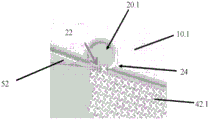
Fig. 3 schematically illustrates the problems that arise if the standard tuft picker 10.1 is used for non-standard filaments, such as X-shaped filaments 42.1 (fig. 3A) or ultra-thin filaments 42.2 (fig. 3B). During the movement of the tuft picker 10.1, the X-shaped filaments 42.1 are transferred into the picker eye 20.1. Thus, the X-shaped filaments 42.1 can be positioned in the openings 22 of the picker eye 20.1. Once the opening 22 of the picker eye 20.1 moves along the counterpart 52 of the tuft picker 10.1, the filaments 42.1 will be spliced by the sharp projection 24. If ultra thin filaments 42.2 are processed with a standard tuft picker 10.1, the filaments 42.2 will be clamped in the gap 26 between the working surface 13.1 of the tuft picker 10.1 and the counterpart 52 (fig. 3B).
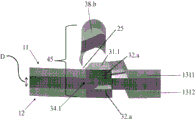
Fig. 4 shows a schematic view of the covering tool 30 mounted between the first and second sections 11, 12 of the tuft picker as shown in fig. 5 and between the first and third sections 11, 14 and the third and second sections 14, 12 of the tuft picker as shown in fig. 6C. The covering tool 30 comprises a hook 31 connected to a body 37 via a spacer 36. The covering tool 30 is rotatably mounted to the sections 11, 12 of the tuft picker via a hinge 39. The hook 31 of the covering tool 30 comprises a first surface 32 and a second surface 33. The form of the first surface 32 corresponds to and is equal to the form of the working surface of the tuft picker. In particular, the form of the first surface 32 of the hook 31 is adapted to match the opening of the picker eye. The two surfaces 32, 33 of the hook 31 are connected via an end 34 which is rounded in order not to damage the filaments to be sorted. The first surface 32 and the second surface 33 are spaced apart by a width W that increases from the end 34 toward the connection of the hook 31 and the spacer 36. A suitable width W at the rounded end 34 is about 0.05mm and a suitable width W at the connection of the hook 31 and the spacer 36 is about 0.4 mm. The second surface 33 may be fastened such that the protuberance 35 is present in the second surface 33. The form of the hook 31 is optimized for transferring filaments positioned in the opening of the picker eye deeper into the free space of the picker eye volume.
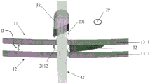
Fig. 5A to 5C illustrate schematic front/top views of the cutting of the first exemplary embodiment of a tuft picker including a picker eye volume 45 according to the present disclosure. Features that are the same as those shown in fig. 4 are denoted by the same reference numerals and will not be described in detail. The tuft picker comprises two parts, a first part 11 and a second part 12, which are spaced apart by a distance D. The covering tool 30 as shown in fig. 4 is arranged within said distance D. The first and second portions 11, 12 of the tuft picker each comprise a working surface 1311, 1312. The covering tool 30 comprises a hook 31, wherein the form of a first surface 32 of the hook 31 corresponds to the form of the working surfaces 1311, 1312. The first and second parts 11, 12 of the tuft picker each comprise one picker eye 2011, 2012, wherein the picker eyes 2011, 2012 are positioned at the same location in the parts 11, 12 of the tuft picker. This means that the working surface 1311 is interrupted by the opening 2211 of the picker eye 2011 and the working surface 1312 is interrupted by the opening 2212 of the picker eye 2012, wherein the openings 2211, 2212 are positioned above each other. The picker eyes 2011 and 2012 are elliptical recesses, where the depth L may be about 1.5mm and the width B may be about 1.0 mm. The volume covered by the first picker eye 2011, the second picker eye 2012, and the distance D therebetween forms a picker eye volume 45 (fig. 5A). Picker eye volume 45 is intended to remove filaments 42 during picking, as shown in fig. 5B. The portion 38 covering the tool is positioned inside the picker eye volume 45, thereby limiting the volume of the picker eye volume 45. The covering tool is movably arranged between the two parts 11, 12 of the tuft picker. For example, the covering means are mounted to the first and second portions 11, 12 of the tuft picker via hinges 39.
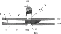
Fig. 5C shows the hook 31 in its second position. Features that are the same as those shown in fig. 4 to 5B are denoted by the same reference numerals and will not be described in detail. The end 34 of the hook 31 is located between the first and second portions 11, 12 at opposite sides of the picker eye opening 2211, 2212 such that the hook 31 closes the shaped line of the picker eye opening 2211, 2212. Thus, a portion of the picker eye volume 45 is covered by the hook 31. The reduction in volume is balanced by the portion 38.B covering less volume of the picker eye volume 45 than in fig. 5A and 5B, so that the final volume of the picker eye volume 45 from which filaments can be removed is constant. Alternatively, the net volume of the picker eye volume 45 may increase slightly, as the volume covered by the hook 31 may be less than the volume released by the portion 38. The slightly increased net volume of picker eye volume 45 makes it easier to transfer filaments from picker eye openings 2211, 2212 into a greater depth of picker eye volume 45.
Fig. 6 presents a schematic view of the embodiment shown in fig. 5 during one working cycle arranged in the tuft picker, wherein the first portion 11 is not shown and the covering tool 30 is shown as translucent. Features that are the same as those shown in fig. 5 are denoted by the same reference numerals and will not be described in detail. The covering tool 30 is movably mounted to the tuft picker 10. The hook 31 is positioned outside of the picker eye 2012, in particular outside of the shaped line of the opening 2212 of the picker eye 2012 (fig. 6A and 6B) in its first position. The portion 38 covering the body of the tool 30 is positioned partially over the picker eye 2012 so that the shim covered by the portion 38 cannot be filled with filaments 42. The opening 2212 of the picker eye 2012 is covered by the counterpart 52 of the tuft picker 10, so that the picker eye 2012 cannot be filled (fig. 6A). Fig. 6B illustrates a filament 42 passing through an opening 2212 into the picker eye 2012, with a counterpart 52 (not shown) positioned outside the area of the picker eye 2012. The hook 31 is then transferred from its first position outside the area of the picker eye 2012 to its second position, wherein the hook 31 is positioned on the forming line of the opening 2212 (fig. 6C). Thereby, the filament 42 is removed from the opening 2212 and transferred deeper into the picker eye 2012. Thus, the portion 38.a, which is positioned partially above the picker eye 2012, is partially removed from the area of the picker eye 2012. The volume released by the main part 38.a of the covering tool corresponds to the volume required by the hook 31. Fig. 6D shows the hook 31 in its second position. The hook 31 is positioned completely in the shaped line of the opening 2212 of the picker eye 2012, closing the picker eye 2012. The portion 38.B of the body still positioned in the area of the picker eye 2012 is minimal compared to the portions 38, 38.a in which the covering tool is positioned when it is in its first position (fig. 6A, 6B) and during movement (fig. 6C). The filaments 42 are securely positioned in the picker eye 20 (fig. 6D) and may be transferred through the picker eye 20 to any further manufacturing steps.
Fig. 7 illustrates another embodiment of a covering tool in which the first position is different from the embodiment shown in fig. 6 and there is an additional ejection position. Features that are the same as those shown in fig. 4 to 6 are denoted by the same reference numerals and will not be described in detail. In the first position of the covering means, the end 34 of the hook 31 projects slightly into the opening 22 of the picker eye volume 45 and the portion 38 covers the base of the picker eye volume 45 (fig. 7A). During the movement of the covering means, the hook 31 moves from said first position to a position inside the picker eye volume 45, i.e. a second position (fig. 7B). Thus, the second surface 32 of the hook 31 is positioned on the line of formation of the picker eye openings 2211, 2212, and the hook 31 is positioned in the picker eye volume 45. Parallel to the movement of the hook 31 inside the picker eye volume 45, the tool-covered portion 38 moves out of the picker eye volume 45. This means that the volume covered by the portion 38.B (fig. 7B) is smaller than the volume covered by the portion 38 (fig. 7A). Thus, the net volume of picker eye volume 45 is constant due to the parallel movement of portion 38 and hook 31. Alternatively, the volume of the picker eye volume 45 may increase slightly from the first position to the second position of the hook 31, which slightly simplifies removal of the filaments from the picker eye opening 22. Fig. 7C shows the additional ejection position. In the ejection position, the hook 31 of the covering tool is completely removed from the opening 22. This means that the end 34 of the hook 31 is positioned completely between the first and second portions 11, 12 of the tuft picker, so that the size of the opening 22 is maximized. At the same time, the base portion 38.C of the covering means moves further into the picker eye volume 45, i.e. the portion 38.C (fig. 7C) is larger than the portion 38 (fig. 7A). The filaments are thereby actively pushed by the portions 38.c in the direction of the opening 22, so that the removal of the filaments from the picker eye volume 45 is simplified. The movement cycle of the covering tool as shown in fig. 7 can be combined with the hook 31 or every other form of the covering tool itself.
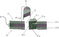
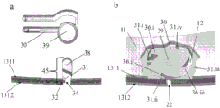
Fig. 8A illustrates a schematic front/top view of the cut of another exemplary embodiment of a tuft picker including a picker eye volume 45 with a covering tool 30 according to the present disclosure. Features that are the same as those shown in fig. 4 to 7 are denoted by the same reference numerals and will not be described in detail. The embodiment of the covering means 30 shown in fig. 8A and 8B comprises different hooks 31.1. Hook 31.1 is U-shaped, wherein the sides of the U-shaped hook 31.1 are positioned in the working surfaces 1311, 1312 of the first and second parts 11, 12 such that the first surface 32.a of the hook 31.1 protrudes from the parts 11, 12. This means that the end 34.1 is not necessarily located between the two parts 11, 12 at the distance D in the first position of the covering tool, but forms part of the working surfaces 1311, 1312. In the second position of the covering means, the hook 31.1 closes the picker eye volume 45 (fig. 8B). Thereby, the end 34.1 and the projection 25 close the working surfaces 1311, 1312 in the area of the picker eye volume 45.
Fig. 8C illustrates a schematic front/top view of the cutting of another exemplary embodiment of the tuft picker comprising a circular covering tool 30. Features that are the same as those shown in fig. 4-8B are denoted with the same reference numerals and will not be described in detail. The circular covering tool 30 comprises four hooks 31i, 31ii, 31iii, 31iv and four spacers 36i, 36ii, 36iii, 36iv arranged around the surface of the covering tool 30. The covering tool 30 is embedded in the first and second parts 11, 12 of the tuft picker via a hinge 39 which holds the covering tool 30 in place but allows it to rotate (fig. 8 Ca). Thus, the covering tool 30 allows different hooks 31i-31iv to be positioned in the picker eye volume 45 (fig. 8 Ca). In fig. 8Cb, the first portion 11 is removed in the area of the overlay tool 30 to fully display the circular overlay tool 30. Due to the fact that the hooks 31i-31iv and the shims 36i-36iv are of different sizes, the final volume of the picker eye volume 45 that can be filled with filaments is different. Thus, different size eyes, i.e. different numbers of filaments to be sorted, can be provided by using a covering tool 30 as shown in fig. 8C.
Fig. 8D illustrates a schematic front/top view of the cutting of another exemplary embodiment of a tuft picker including picker eye volume 45 according to the present disclosure. Features that are the same as those shown in fig. 4-8B are denoted with the same reference numerals and will not be described in detail. The tuft picker shown in fig. 8C comprises three parts, namely a first part 11, a second part 12 and a third part 14. The third portion 14 is positioned between the first portion 11 and the second portion 12, wherein the first portion 11 and the third portion 14 and the second portion 12 are separated by a distance D, respectively. Inside each of said distances D a covering tool is arranged, wherein the covering tools are positioned at the same location and have the same shape and size as each other. The first, second and third portions 11, 12, 14 of the tuft picker each comprise a working surface 1311, 1312, 1314. The covering means each comprise hooks, wherein only the first surface 32.1, 32.2 of each hook can be seen in fig. 8C. The form of the first surface 32.1, 32.2 of the hook corresponds to the working surface 1311, 1312, 1314. The first, second and third sections 11, 12, 14 of the tuft picker each comprise one picker eye positioned at the same location in the sections 11, 12, 14. This means that the working surfaces 1311, 1312, 1314 are interrupted by openings 2211, 2214, 2212, respectively, wherein the openings 2211, 2214, 2212 are positioned on top of each other. The volume covered by the picker eyes in the first, second and third sections 11, 12, 14 and the distance D therebetween forms the picker eye volume 45, which is intended to remove filaments during picking. The portions 38.1, 38.2 of the covering means are positioned inside the picker eye volume 45, thereby limiting the volume of the fillable picker eye volume 45. The covering means are movably arranged between the first and third portions 11, 14 and between the third and second portions 14, 12. For example, the covering means are mounted to the tuft picker portions 11, 12, 14 via hinges 39. Mounting two covering tools with one hinge 39 allows the covering tools to move parallel compared to the picker eye volume 45.
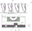
Fig. 9 illustrates a schematic top view of a linear tuft picker 10 according to the invention comprising several picker eyes 20 arranged next to each other in a straight working surface 1311, 1312. Features that are the same as those shown in fig. 4 and 5 are denoted by the same reference numerals and will not be described in detail. Four picker eyes 20 are arranged next to one another in the linear tuft picker 10. The picker eyes 20 each include an overlay tool as disclosed above and shown in more detail in fig. 5. The detailed view in fig. 9 shows the covering tool 30 during movement from its first position to its second position. The hook 31 is partially positioned in the shaped line of the opening 2211, 2212 of the picker eye 20 and the portion 38.a is partially removed.
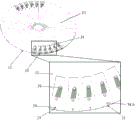
Fig. 10 shows a schematic top view of a circular tuft picker 10 according to the invention comprising several picker eyes 20, which are arranged next to each other. Features that are the same as those shown in fig. 4 and 5 are denoted by the same reference numerals and will not be described in detail. Six picker eyes 20 are arranged next to one another on the circular working surface 13 of the tuft picker 10. Two sets of six picker eyes 20 are arranged at opposite sides of the tuft picker circle 10. The picker eyes 20 each include an overlay tool as disclosed above and shown in more detail in fig. 5. The detailed view in fig. 10 shows the five covering tools 30 at different points in time during the movement from their first position to their second position. For example, the first picker eye 20 shown on the left is fully open, i.e. the covering tool is arranged in its first position. Thus, portion 38 is positioned entirely in the picker eye and the hook is removed from the opening of the picker eye. The picker eye 20 shown on the right side of the detailed view is fully closed, i.e. the covering tool is arranged in its second position. Thus, the hook 31 closes the opening 22 of the picker eye 20 and the portion 38.b is removed from the picker eye, so that the volume of the picker eye remains constant.
The dimensions and values disclosed herein are not to be understood as being strictly limited to the exact numerical values recited. Rather, unless otherwise specified, each such dimension is intended to mean both the recited value and a functionally equivalent range surrounding that value. For example, a dimension disclosed as "40 mm" is intended to mean "about 40 mm".