CN1099224C - Process for shielding an electric or electronic circuit and shielding cap - Google Patents
Process for shielding an electric or electronic circuit and shielding cap Download PDFInfo
- Publication number
- CN1099224C CN1099224C CN97198819A CN97198819A CN1099224C CN 1099224 C CN1099224 C CN 1099224C CN 97198819 A CN97198819 A CN 97198819A CN 97198819 A CN97198819 A CN 97198819A CN 1099224 C CN1099224 C CN 1099224C
- Authority
- CN
- China
- Prior art keywords
- radome
- gasket
- coating
- conduction
- buckling surface
- Prior art date
- Legal status (The legal status is an assumption and is not a legal conclusion. Google has not performed a legal analysis and makes no representation as to the accuracy of the status listed.)
- Expired - Lifetime
Links
- 238000000034 method Methods 0.000 title claims abstract description 47
- 230000008569 process Effects 0.000 title abstract description 7
- 238000007789 sealing Methods 0.000 claims abstract description 20
- 238000000576 coating method Methods 0.000 claims description 78
- 239000011248 coating agent Substances 0.000 claims description 75
- 229920001971 elastomer Polymers 0.000 claims description 17
- 239000000806 elastomer Substances 0.000 claims description 17
- 239000002184 metal Substances 0.000 claims description 11
- 229910052751 metal Inorganic materials 0.000 claims description 11
- 229910000639 Spring steel Inorganic materials 0.000 claims description 9
- 238000009413 insulation Methods 0.000 claims description 7
- 239000007788 liquid Substances 0.000 claims description 6
- 239000004033 plastic Substances 0.000 claims description 6
- 229920003023 plastic Polymers 0.000 claims description 6
- 230000015572 biosynthetic process Effects 0.000 claims description 4
- 239000000463 material Substances 0.000 claims description 4
- 230000005855 radiation Effects 0.000 claims description 4
- 239000012945 sealing adhesive Substances 0.000 claims description 4
- 229910052710 silicon Inorganic materials 0.000 claims description 4
- 239000010703 silicon Substances 0.000 claims description 4
- 229920001169 thermoplastic Polymers 0.000 claims description 4
- 239000004416 thermosoftening plastic Substances 0.000 claims description 4
- 239000011231 conductive filler Substances 0.000 claims description 3
- 230000005611 electricity Effects 0.000 claims description 3
- 239000011159 matrix material Substances 0.000 claims description 3
- 229920002635 polyurethane Polymers 0.000 claims description 3
- 239000004814 polyurethane Substances 0.000 claims description 3
- 239000011810 insulating material Substances 0.000 claims description 2
- 230000013011 mating Effects 0.000 claims description 2
- 238000007747 plating Methods 0.000 claims description 2
- 238000005510 radiation hardening Methods 0.000 claims description 2
- 239000000945 filler Substances 0.000 claims 1
- -1 poly-aminomethyl acetoacetic ester Chemical compound 0.000 claims 1
- 238000005507 spraying Methods 0.000 claims 1
- 230000005670 electromagnetic radiation Effects 0.000 abstract 1
- 230000003094 perturbing effect Effects 0.000 abstract 1
- 239000010410 layer Substances 0.000 description 9
- 208000034189 Sclerosis Diseases 0.000 description 7
- 238000003618 dip coating Methods 0.000 description 5
- 239000000243 solution Substances 0.000 description 5
- 238000001465 metallisation Methods 0.000 description 4
- 229910000831 Steel Inorganic materials 0.000 description 3
- 239000011888 foil Substances 0.000 description 3
- 239000010959 steel Substances 0.000 description 3
- 238000003466 welding Methods 0.000 description 3
- 230000008901 benefit Effects 0.000 description 2
- 229910052802 copper Inorganic materials 0.000 description 2
- 239000010949 copper Substances 0.000 description 2
- 238000009826 distribution Methods 0.000 description 2
- 239000008393 encapsulating agent Substances 0.000 description 2
- 238000005470 impregnation Methods 0.000 description 2
- 230000001105 regulatory effect Effects 0.000 description 2
- 230000007704 transition Effects 0.000 description 2
- 238000009736 wetting Methods 0.000 description 2
- OKTJSMMVPCPJKN-UHFFFAOYSA-N Carbon Chemical compound [C] OKTJSMMVPCPJKN-UHFFFAOYSA-N 0.000 description 1
- RYGMFSIKBFXOCR-UHFFFAOYSA-N Copper Chemical compound [Cu] RYGMFSIKBFXOCR-UHFFFAOYSA-N 0.000 description 1
- 239000000654 additive Substances 0.000 description 1
- 230000000996 additive effect Effects 0.000 description 1
- 238000004026 adhesive bonding Methods 0.000 description 1
- 238000005452 bending Methods 0.000 description 1
- 238000007664 blowing Methods 0.000 description 1
- 229910052799 carbon Inorganic materials 0.000 description 1
- 239000011247 coating layer Substances 0.000 description 1
- 230000006835 compression Effects 0.000 description 1
- 238000007906 compression Methods 0.000 description 1
- 150000001879 copper Chemical class 0.000 description 1
- 230000001419 dependent effect Effects 0.000 description 1
- 238000010586 diagram Methods 0.000 description 1
- 239000000428 dust Substances 0.000 description 1
- 230000000694 effects Effects 0.000 description 1
- 230000002349 favourable effect Effects 0.000 description 1
- 238000005213 imbibition Methods 0.000 description 1
- 230000006872 improvement Effects 0.000 description 1
- 230000008595 infiltration Effects 0.000 description 1
- 238000001764 infiltration Methods 0.000 description 1
- 238000001746 injection moulding Methods 0.000 description 1
- 230000002045 lasting effect Effects 0.000 description 1
- 238000012423 maintenance Methods 0.000 description 1
- 238000004519 manufacturing process Methods 0.000 description 1
- 150000002739 metals Chemical class 0.000 description 1
- 239000000203 mixture Substances 0.000 description 1
- 239000000843 powder Substances 0.000 description 1
- 230000001681 protective effect Effects 0.000 description 1
- 230000008439 repair process Effects 0.000 description 1
- 238000012216 screening Methods 0.000 description 1
- 238000007493 shaping process Methods 0.000 description 1
- 238000002791 soaking Methods 0.000 description 1
- 238000005476 soldering Methods 0.000 description 1
- 238000001228 spectrum Methods 0.000 description 1
Images


Classifications
-
- H—ELECTRICITY
- H05—ELECTRIC TECHNIQUES NOT OTHERWISE PROVIDED FOR
- H05K—PRINTED CIRCUITS; CASINGS OR CONSTRUCTIONAL DETAILS OF ELECTRIC APPARATUS; MANUFACTURE OF ASSEMBLAGES OF ELECTRICAL COMPONENTS
- H05K9/00—Screening of apparatus or components against electric or magnetic fields
- H05K9/0007—Casings
- H05K9/0015—Gaskets or seals
-
- H—ELECTRICITY
- H05—ELECTRIC TECHNIQUES NOT OTHERWISE PROVIDED FOR
- H05K—PRINTED CIRCUITS; CASINGS OR CONSTRUCTIONAL DETAILS OF ELECTRIC APPARATUS; MANUFACTURE OF ASSEMBLAGES OF ELECTRICAL COMPONENTS
- H05K9/00—Screening of apparatus or components against electric or magnetic fields
Abstract
A process is disclosed for shielding an electric or electronic circuit, preventing it from absorbing and/or emitting perturbing electromagnetic radiation. An electroconductive shielding cap (14) is provided at its contact surface (15) with an elastic and electroconductive shielding gasket (16) which extends beyond the contact surface (15), and is then set and fixed together with the shielding gasket (16) on an electroconductive frame which surrounds the circuit. The process is simplified in that the shielding gasket (16) is formed by directly applying a sealing mass (21) on the contact surface (15).
Description
The present invention relates to the scope of electromangnetic spectrum.It relates to a kind of screen method that prevents to absorb and/or radiate the electric or electronic circuit of electromagnetic interference (EMI) emissions, in this method, conductive shield covers on and scribbles the shield gasket that protrudes in the flexible of this buckling surface and conduction on the buckling surface, then this shield gasket is posted and fixed on the conductive pane of this circuit of encirclement.
In addition, the present invention relates to a kind of radome that prevents to absorb and/or launch the electric or electronic circuit shielding usefulness of electromagnetic interference (EMI) emissions, this radome has a buckling surface on the conductive pane that this radome is fitted to surround this circuit, and scribbles a kind of shield gasket that protrudes in the elasticity and the conduction of this buckling surface on this buckling surface.
For example German utility model G 66071805 discloses this method and this radome.
In order to prevent to receive and/or to launch particularly the electronic circuit of high-frequency electromagnetic interference field or the electromagnetic shielding of branch road, circuit or branch road shield with the radome cup-shaped or flute profile of conduction.For this reason, radome is fitted on the conductive pane with its edge or with a buckling surface, and this frame surrounds and fix this circuit.This frame for example can be the layer of copper layer, and this copper layer is arranged on the upside of the printed circuit board of this circuit of supporting.
When using radome, the electrically contacting evenly well between radome and frame that the one side requirement is extended on the whole edge of radome needs radome to fixedly secure on screening-off position on the other hand again, and this is inconvenient.For the buckling surface of radome can cooperate the unevenness on this frame and prevent to occur undesirable hole in shielding, the edge of radome for example makes flexible or is connected with the frame maintenance by a contact spring leaf.In addition, above-mentioned document suggestion as the transition between buckling surface and the frame, is adopted a kind of shield gasket of elastically deformable of conduction.If shielding comprises a lid, then shield gasket is made up of the plane sponge layer of one deck on the downside of this lid, this froth bed or the additive (carbon dust or metal powder) by conduction itself conduct electricity, perhaps by evaporated metal or be stained with layer of metal film and make its conduction.If shielding comprises a radome, then on the edge of this cover, constitute a groove, in this groove, put into a ring of making by foamed material, this ring or itself are conducted electricity, and perhaps make its conduction by face coat.In order to constitute this groove, on the deep-draw edge of radome, fix on the inboard of a formation of lots steel plate by means of spot welding.When making radome, the formation of this groove not only needs sizable surcharge, but also need take additional position.In addition, under the complex geometry of radome and polygonal situation, this groove is to be difficult to make.
So the present invention is intended to propose a kind of screen method and a kind of radome of electric or electronic circuit, this radome is reaching simplicity and the flexibility that has height under the situation of fine shield effectiveness in use.
In said method, this purpose is achieved in that by directly coat gasket coating on buckling surface and forms shield gasket.Directly on buckling surface, be coated with gasket coating and do not need groove or other particular groove to be set by the present invention for sealing.When the button of radome made simple edge comprehensively, this especially had advantage.Gasket coating directly is coated on the end face at edge according to (may be complicated) edge trend, and strong bond there.Thereby only with minimum area with only just realized the shield gasket of the best of radome with minimum (costliness) gasket coating.
According to the present invention, first preferred embodiment of this method is characterised in that, by a nozzle gasket coating is coated on the buckling surface by means of a proportioner at least with the form of a bar.By means of a kind of like this be used in other occasion promptly be used for screening can for example can be with paste or liquid gasket coating by accurately quantitatively and be applied directly to the edge of radome with the shape of cross section of being scheduled at DE-C2-43 19 965 disclosed coating methods.At three movably under the situation of the corresponding control (programmable) of proportioner, also can apply the edge geometry of the complexity of radome.Wherein, the characteristic of gasket coating is preferably adjusted like this, and promptly the sealing strip made from gasket coating is coated on the edge, sclerosis on the edge and not flowing.In a kind of improvement of this embodiment, in order to form shield gasket, overlappingly several sealing strips have been applied.But shield gasket reaches bigger height and bigger error between balance frame and the buckling surface like this.
In second preferred embodiment of the inventive method, adopt mobile gasket coating, and the buckling surface of radome is immersed in the solution made from gasket coating, retrieve then.Gasket coating soaks into the edge of radome or detains comprehensively, and constitutes the protuberance at an encirclement edge when taking out owing to surface tension, and such protuberance (after sclerosis) constitutes the shield gasket around the edge.The advantage of this embodiment is, just can apply whole edge with shield gasket simultaneously in quick and simple mode and without the applying device and the proportioning device of numerical control.The thickness of the shield gasket of Xing Chenging is mainly decided by the characteristic of gasket coating in the solution like this, and can by impregnation process repeatedly repeat control.If gasket coating is a kind of (infiltration) material that hardens under air humidity, then impregnation process can carry out under a kind of protective atmosphere.
As the gasket coating elastomer of handy a kind of conduction, particularly contain the silicon or the polyurethane of conductive filler.Thereby can be directly coating by gasket coating produce shield gasket, and do not need the operation of adding.For example the composition of this gasket coating can be learnt from European Patent Application No. Nr 0 643 551 and 0 643 552.
As the elastomer of gasket coating also available electric insulation, this gasket coating adds the coating of one deck conduction, the coating of the form that particularly metallizes again after being coated on the buckling surface.Make with a kind of material of electric insulation and after gasket coating is coated onto on the buckling surface at radome, radome and gasket coating cover the coating of last layer conduction jointly, during particularly with the conductive coating of metallization form, and this production method is particularly advantageous.Thereby the gasket coating that is difficult to process with part that can cancel expensive conduction, and radome can be made of plastic, and this plastics can be easy to make different structures with general plastic working method (injection moulding, blowing etc.).
Within the scope of the present invention, the fixing available different mode of the radome behind the fastening is carried out.According to a preferred embodiment, radome carries out mechanical fixation after fastening on the frame.In order to realize mechanical fixation, the radome that the most handy a kind of aid will have shield gasket is pressed onto on the frame, this aid especially comprises a spring clip, screw, opposed housing parts or spring steel plate, this spring steel plate is attached on the radome, particularly the part of the radome made of steel plate.
According to another preferred embodiment, radome adheres on the frame after fastening on the frame that has shield gasket.This available following method realizes: on the one hand can be with a kind of elastomer of conduction as encapsulant, it has sticking or wet denseness, can fasten to after-hardening on the frame by temperature or radiation hardening and at radome, or with a kind of elastomer of conduction, it still has certain sticking and wet denseness after sclerosis; On the other hand, as the thermoplastics of encapsulant also available a kind of conduction or a kind of heat sealing adhesive of conduction, and be bonded on the frame by elevated temperature after fastening to radome on the frame.
Radome of the present invention is characterised in that shield gasket forms one with a kind of gasket coating on buckling surface.
According to the present invention, a preferred structure pattern of radome is characterised in that buckling surface makes edge shape, shield gasket or be placed on the end face at edge, and perhaps shield gasket encases the edge.
Other structural shape can be learnt in every dependent claims.
Describe the present invention in detail below in conjunction with embodiment more shown in the drawings.
Accompanying drawing is represented:
Fig. 1 represents an exemplary circuit on the printed circuit board, and (Fig. 1 is not a) and have a end view (Fig. 1 b) under the radome situation that is shown in dotted line there being plane graph under the radome situation.
The perspective view of radome shown in Fig. 2 presentation graphs 1b (uncovered downward);
Fig. 3 represents that first preferred embodiment according to the inventive method is coated in the shield gasket on Fig. 2 radome, wherein, radome at first makes progress its uncovered (edge), and (Fig. 3 a) is coated to (Fig. 3 b) on the edge with a proportioner that moves with shield gasket then in placement;
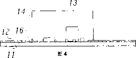
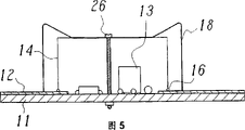
Fig. 4-6 is illustrated in the end view of the various exemplary fixed form of scope of the invention inner shield, promptly by means of a kind of gluing shield gasket (Fig. 4), (Fig. 6) realizes fixing on an opposed housing parts or the similarity piece by a spring clip and/or a screw (Fig. 5) with by being supported on;
Fig. 7 a-c represents that second preferred embodiment according to the present invention immerses radome the different step that produces shield gasket in the solution made from (liquid state) gasket coating;
The section of the various shield gasket of Fig. 8-10 expression the present invention: make (Fig. 8) by soaking into, or by according to Fig. 3 second coat sealing strip (Fig. 9) according to Fig. 7, or the metallization (Figure 10) by nonconducting sealing;
Figure 11 represents to be equivalent to Fig. 3 b shield gasket is coated on the fixing radome of available spring steel plate;
Figure 12 represents that with the fixing end view of Figure 11 radome of spring steel plate these spring steel plates insert in the printed circuit board by the hole and elasticity fastens.
Fig. 1 is illustrated in the plane graph of an exemplary circuit on the printed circuit board, and (Fig. 1 a) and end view (Fig. 1 b).This circuit 10 comprises a printed circuit board 11 (printed circuit or stacked printed circuit board), and a center range on this circuit board is arranged some electronic components 13 (resistance, electric capacity, diode, integrated circuit, or the like) and interconnected.These elements 13 constitute a branch road, and this branch road shields with respect to other branch roads or environment, in order to avoid the electromagnetic interference field outwards launches from this branch road, or absorb this interference field from the external world.For this reason, the frame 12 of a conduction of this route surrounds with the metallization form of printed circuit board 11 upsides.Certain this branch road, the structure of frame 12 and circuit 10 also can have another pattern and structure.
Shielding with branch road of element 13 is carried out with a cup-shaped radome 14 (shown in Fig. 1 b dotted line), and the perspective view of this radome as shown in Figure 2.This radome 14 has the shape of a rectangular box in the example shown.When also can being circular at this radome or the oblique angle, and can have jog.This radome 14 can be formed by a block plate bending, welding or shaping (deep-draw); But also the plastics of available plating are made.Radome 14-shown in Fig. 1 b-be placed on above the branch road.The edge that limits the uncovered limit of radome 14 constitutes a buckling surface, and is fitted on the frame 12, to set up from radome 14 to frame 12 a transition sealing and conduction.
In order to offset unevenness, the shield gasket of a kind of flexible and conduction of coating between the edge of radome 14 or buckling surface and frame 12, sealing connects electrically contacting and can offset several 1/10 millimeter tolerances between radome 14 and the frame 12.According to a first advantageous embodiment of the invention, shield gasket is to produce like this and be coated on the radome 14, and the gasket coating that promptly constitutes this shield gasket directly applies (extruding) on the edge with the form of at least one rule.For this reason, according to Fig. 3 a, the buckling surface 15 at radome 14 its edges of usefulness upwards is put into the work bottom of a proportioner, resemble it according to Fig. 3 b proportioner 17 then and for example as described in DE-C2-43 19 965, move, (preferably paste or thixotroping) gasket coating 21 is unloaded with the form of a rule from a nozzle 25 be placed on the buckling surface 15 and constitute shield gasket 16 at numerical control lower edge buckling surface 15.Under the general wall thickness (steel plate thickness) of radome 14 was several 1/10 millimeter situation, (being generally circular) diameter of bar was about the scope of 0.2-2 millimeter.
The performance of gasket coating 21 is to regulate like this, and promptly sealing strip can keep its shape and cross section basically after being put on the buckling surface 15 on the one hand, is bonded in again on this mating surface on the other hand.Preferably adopt a kind of silicon of conductive filler or conduction elastomer that polyurethane is matrix of containing as gasket coating 21, or a kind of elastomer of electric insulation, wherein gasket coating 21 is coated with one deck conductive layer, the conductive layer 24 of the form that particularly metallizes after being coated on the buckling surface 15.
Gasket coating 21 both can have solid-state denseness, also can be compliant or the denseness of viscosity.When radome 14 not necessarily planned to adhere on the frame 12, this gasket coating can be directly by air humidity sclerosis or wetting.But for example when radome 14 usefulness shield gaskets adhered on the frame 12, then this gasket coating also can be wetting by heat or radiation (ultraviolet radiation, infrared radiation or X-radiation or laser emission).In this case, just harden after having only radome 14 to put.If adopt after sclerosis the still gasket coating of toughness, then radome also can be bonding after sclerosis.For this reason, also can imagine heat sealing adhesive with a kind of thermoplastics of conduction or a kind of conduction as gasket coating, and after radome 14 fastens on the frame 12, be bonded on the frame 12 by corresponding elevated temperature.As plastics gasket coating 21 equally also available a kind of conduction or isotropic.
If according to Fig. 3 b as gasket coating 21 coating be a kind of like this coating, promptly its performance allows that radome 14 directly is bonded on the frame, the radome 14 that then is coated with shield gasket 16 can directly fasten and be bonded in (Fig. 4) on the frame 12.If bonding force then can be cancelled additional fixedly householder method in this case to lasting the fixing enough of radome 14, this has just made things convenient for use widely.If bonding force is not enough, perhaps shield gasket then must adopt additional (mainly being mechanical) householder method to fix radome 14 according to there not being bonding effect.In Fig. 5 example, adopt a spring clip 18, this spring clip is fixed on the printed circuit board 11 with its end, and is pressed onto on the radome 14 from the top with its flexible middle part.Without spring clip 18, also available other clip or similar fixture.In addition, without spring clip 18 or except spring clip 18, also available (or a plurality of) screw 26, this screw or insert in the radome 14 and with printed circuit board 11 by hole are connected, or insert in the printed circuit board 11 by a hole and also to be connected with radome 14 with a pad.Fig. 6 represents the another kind of possibility of fixing, and utilizes an opposed housing parts 19 or similarity piece here, so that radome 14 is pressed onto on the printed circuit board 11, printed circuit board itself then is bearing on the part 20.
A kind of simple especially and convenient fixing means that uses when Figure 11 and 12 expression radomes are made of metallic plate.Radome 14 used herein has one at least, but best two or more mutual opposed spring foil metals 27,28.The spring foil metal 27,28 of this bar shaped extends upward and is bent into hook-type from buckling surface 15.They can be one as shown in figure 11-make the part of the metallic plate of radome 14, but also available independent bonding jumper is made and spot welding, riveted joint, bonding or soldering on radome 14.In this class situation, each sheet 27,28 of spring is preferably outwardly-bent a little, so that buckling surface 15 is continuously with shield gasket 16 coatings.
Is furnished with the radome of spring foil metal 27,28-be similar to shown in Fig. 3 b-with shield gasket 16 coatings.And then radome 14 can mechanically be fixed on the printed circuit board 11 with spring steel plate 27,28 according to Figure 12.For this reason, be provided with the through hole 29,30 (shown in Figure 12 dotted line) of slotted hole for example or flute profile formula on the suitable position of printed circuit board 11, when radome 14 fastened, spring steel plate 27,28 passes these holes and elasticity buckles into.Thereby it is simple, yet reliable especially fixing that radome 14 is realized, and be suitable for automation processing, and part and installment work only need surcharge seldom.In addition, Gu Ding radome 14 takes off easily and reuses when safeguarding or repair like this, promptly being supported on the spring steel plate compression on printed circuit board 11 downsides and 29,30 withdrawing from the hole.
The method of proportioner of usefulness shown in Figure 3 17 coating shield gaskets 16 needs corresponding device thereof.In addition, the digital control of proportioner 17 must be regulated by the programming of corresponding radome 14 edges trend.If shield gasket is coated on the buckling surface 15 of radome 14 with the another kind of for example method shown in Fig. 7 schematic diagram (" dip coating "), then can obviously reduces the required expense of device.Using under the dip coating situation, (Fig. 7 a) immerses the gasket coating 21 that (Fig. 7 b) in the solution of gasket coating 21 liquid state or viscosity be arranged in container 22 should have flat as far as possible liquid level to the uncovered or buckling surface 15 of radome 14 downwards.When radome 14 usefulness edges slowly and equably immerse gasket coating 21 several 1/10 millimeter the time, then gasket coating 21 soaks into these edges.When radome 14 took out from solution, because surface tension forms the annular protrusion of a gasket coating around the radome edge, after sclerosis, this protuberance formed shield gasket 16 (Fig. 7 C that firmly is connected with the edge; See Fig. 8 sectional drawing).
Mode can apply very uniform shield gasket with very simple method on the whole edge of radome 14 in unique process according to this.Wherein, the performance of gasket coating (at liquid and non-profit temperature state) must be regulated like this, and promptly imbibition characteristic and surface tension should be able to provide the result of requirement.Here be also pointed out that under the situation of dip coating the buckling surface 15 of radome 14 preferably is positioned at a plane.If buckling surface 15 is positioned at different planes, then should adopt distribution shown in Figure 3, in this method, proportioner 17 can move in three.
It mainly is a kind of circular cross section of shield gasket 16 that the distribution of Fig. 3 produces, and the easier cross section that causes a kind of shape shown in Figure 8 of the dip-coating rule of Fig. 7.If shield gasket 16 will offset bigger error, then must increase its height of state.This can realize by the diameter that strengthens shield gasket, but needs the gasket coating of considerable additional costliness like this.On the contrary, put many sealing strip 16a, b according to Fig. 9 with Fig. 3 method is overlapping, it is more favourable that they form 16 of narrow, a high shield gasket together then.
The another kind of possibility that forms a kind of conductive shield sealing 16 as shown in figure 10.Shield gasket 16 comprises a sealed core 23 of being made by a kind of elastomer of electric insulation herein, the outside coating layer of metal layer 24 of sealing core.Sealing core 23 can apply by mode shown in Figure 3, but also available dip coating shown in Figure 7 produces.Metallization can be undertaken by the mode of knowing.When a kind of electrical insulating material of radome 14 usefulness is made, this scheme advantageous particularly then.In this case, after gasket coating was coated on the buckling surface 15, radome 14 and gasket coating were the coating of sealed core 23 common coating one deck conductions, the deposited metal 24 of the form that particularly metallizes.
Generally speaking, can realize a kind of simply and use screen method or radome flexibly with the present invention, and processing charges is low, has high shielding quality simultaneously.
Claims (28)
1. screen method that prevents to absorb and/or radiate the electric or electronic circuit (10) of electromagnetic interference (EMI) emissions, in this method, electrically conductive shield (14) scribbles a kind of shield gasket (16) that protrudes from the elasticity and the conduction of this buckling surface (15) on a buckling surface (15), and fit and be fixed on the conductive pane (12) of surrounding this circuit (10) with this shield gasket (16), it is characterized in that this shield gasket (16) is gone up formation by a kind of gasket coating (21) being applied directly to this buckling surface (15).
2. by the method for claim 1, it is characterized in that sealing coating is coated on the mating surface (15) by the form of a nozzle (25) with at least one rule by means of a proportioner (17).
3. by the method for claim 2, it is characterized in that, in order to form shield gasket (16), many sealing strips of overlapping coating (16a, b).
4. press the method for claim 1, it is characterized in that, with a kind of liquid airproof coating (21) time, sealing coating (21) is to be coated to like this on the buckling surface (15), being radome (14) immerses in a kind of solution made from sealing coating (21) with its buckling surface (15), pulls out again immediately.
5. by each method in the claim 1 to 4, it is characterized in that, can be with a kind of elastomer of conduction as gasket coating.
6. by the method for claim 5, it is characterized in that with a kind of conductive elastomer that is matrix with silicon or poly-aminomethyl acetoacetic ester, this elastomer contains the filler of conduction.
7. by each method in the claim 1 to 4, it is characterized in that, as gasket coating with a kind of electric insulation elastomer, and coating one deck conducts electricity after sealing coating is coated onto buckling surface (15) and goes up coating, particularly sprayed metal layer (24).
8. press the method for claim 7, it is characterized in that radome (14) is made with a kind of material of electric insulation, and after gasket coating is coated onto buckling surface (15), radome (14) and gasket coating are provided with the coating, particularly sprayed metal layer (24) of one deck conduction jointly.
9. by each method in the claim 1 to 4, it is characterized in that, as gasket coating with plastics a kind of conduction or isotropic.
10. by each method in the claim 1 to 4, it is characterized in that, radome (14) fastening to carry out after frame (12) is gone up mechanical fixing.
11. the method by claim 10 is characterized in that, for mechanical fixing, adopts some auxiliary members (18,19,26,27,28), they are pressed onto the radome (14) that scribbles shield gasket (16) on the frame (12).
12. the method by claim 11 is characterized in that auxiliary member comprises a spring clip (18).
13. the method by claim 11 is characterized in that auxiliary member comprises a screw (26).
14. the method by claim 11 is characterized in that auxiliary member comprises an opposed outer casing member (19).
15. the method by claim 11 is characterized in that auxiliary member comprises spring steel plate (27,28), they are arranged on the radome (14).
16., it is characterized in that radome (14) is bonded on the frame (12) with shield gasket (16) after frame (12) is gone up fastening to by each method in the claim 1 to 4.
17. the method by claim 16 is characterized in that, as the elastomer of gasket coating with a kind of conduction, this elastomer has viscous or wet denseness.
18. the method by claim 17 is characterized in that gasket coating can pass through temperature or radiation hardening, and hardens after radome (14) is fastened on the frame (12).
19. by the method for claim 16, it is characterized in that, with a kind of thermoplastics of conduction or a kind of heat sealing adhesive of conduction, and fasten to frame (12) at radome (14) and go up and be bonded on the frame (12) later on by elevated temperature as gasket coating.
20. a kind of radome (14) by the described method of claim 1, this radome (14) has a buckling surface (15), so that this radome (14) is fastened on the conductive pane (12) of this circuit of encirclement (10), and at a kind of shield gasket (16) that protrudes from the elasticity and the conduction of this buckling surface (15) of the last coating of buckling surface (15), it is characterized in that, go up the formation one at buckling surface (15) with the shield gasket (16) that a kind of gasket coating (21) is made.
21. the radome by claim 20 is characterized in that buckling surface (15) is as edge shape, shield gasket (16) then is positioned on the end face at this edge.
22. the radome by claim 20 is characterized in that buckling surface (15) makes edge shape, shield gasket (16) then surrounds this edge.
23., it is characterized in that shield gasket (16) has the shape of one or more sealing strip 16a, b by each radome in the claim 20 to 22.
24. by each radome in the claim 20 to 22, it is characterized in that, shield gasket (16) by a kind of elastomer of conduction, particularly by a kind of contain conductive filler, be that the elastomer of matrix is made with silicon or polyurethane.
25. the radome by claim 24 is characterized in that the elastomer of conduction has denseness a kind of viscous or hygrometric state, and can harden by temperature or radiation.
26., it is characterized in that shield gasket (16) is made up of a kind of thermoplastics of conduction or a kind of heat sealing adhesive of conduction by each radome in the claim 20 to 22.
27., it is characterized in that shield gasket (16) comprises the sealed core (23) that an a kind of electric insulation elastomer of usefulness is made, sealing core spraying plating layer of metal (24) by each radome in the claim 20 to 22.
28., it is characterized in that this radome is made up of a kind of insulating material of metalling by each radome in the claim 20 to 22.
Applications Claiming Priority (2)
| Application Number | Priority Date | Filing Date | Title |
|---|---|---|---|
| DE19634174 | 1996-08-18 | ||
| DE19634174.4 | 1996-08-18 |
Publications (2)
| Publication Number | Publication Date |
|---|---|
| CN1233387A CN1233387A (en) | 1999-10-27 |
| CN1099224C true CN1099224C (en) | 2003-01-15 |
Family
ID=7803550
Family Applications (1)
| Application Number | Title | Priority Date | Filing Date |
|---|---|---|---|
| CN97198819A Expired - Lifetime CN1099224C (en) | 1996-08-18 | 1997-08-18 | Process for shielding an electric or electronic circuit and shielding cap |
Country Status (10)
| Country | Link |
|---|---|
| US (1) | US6420649B1 (en) |
| EP (1) | EP0919114B1 (en) |
| JP (1) | JP2001503199A (en) |
| KR (1) | KR100397660B1 (en) |
| CN (1) | CN1099224C (en) |
| AT (1) | ATE496521T1 (en) |
| AU (1) | AU3705497A (en) |
| DE (2) | DE19780883D2 (en) |
| TW (1) | TW486238U (en) |
| WO (1) | WO1998008365A1 (en) |
Families Citing this family (47)
| Publication number | Priority date | Publication date | Assignee | Title |
|---|---|---|---|---|
| DE4319965C3 (en) * | 1993-06-14 | 2000-09-14 | Emi Tec Elektronische Material | Method of manufacturing an electromagnetic shielding case |
| CA2129073C (en) * | 1993-09-10 | 2007-06-05 | John P. Kalinoski | Form-in-place emi gaskets |
| US20070137653A1 (en) * | 2000-03-13 | 2007-06-21 | Wood Thomas J | Ventilation interface for sleep apnea therapy |
| JP3287330B2 (en) * | 1999-04-22 | 2002-06-04 | 日本電気株式会社 | High frequency circuit shield structure |
| JP4433519B2 (en) * | 1999-08-16 | 2010-03-17 | 株式会社ニコン | Electronic camera |
| DE19943657A1 (en) * | 1999-09-13 | 2001-04-12 | Altoflex S A | Method and device for producing an electromagnetically shielded housing |
| MXPA02003659A (en) * | 1999-10-15 | 2003-05-23 | Siemens Canada Ltd | Method to create a hot melt form for use with an air induction assembly. |
| WO2001054466A1 (en) * | 2000-01-22 | 2001-07-26 | Helmut Kahl | Method for producing an electromagnetic shield |
| JP2001326290A (en) * | 2000-03-10 | 2001-11-22 | Seiko Epson Corp | Method for sealing package, method for manufacturing electronic element module, apparatus for sealing and package article |
| DE10064968B4 (en) * | 2000-12-23 | 2006-01-19 | Helmut Kahl | Method for producing a shielding gasket |
| US6850387B2 (en) * | 2001-01-17 | 2005-02-01 | Seagate Technology Llc | Form-in-place gasket height variability control for a disc drive |
| JP2002344187A (en) * | 2001-05-17 | 2002-11-29 | Nippon Mektron Ltd | Method of manufacturing gasket of electronic equipment |
| CN100407886C (en) * | 2002-03-11 | 2008-07-30 | 赫尔穆特·卡尔 | Equipment cover with one electromagnetic shielding area |
| US7245896B2 (en) * | 2002-06-24 | 2007-07-17 | Lg Electronics Inc. | Apparatus for improving reception sensitivity of public wave receiver by reducing noise externally-emitted in the public wave receiver |
| US7326862B2 (en) | 2003-02-13 | 2008-02-05 | Parker-Hannifin Corporation | Combination metal and plastic EMI shield |
| US7005573B2 (en) | 2003-02-13 | 2006-02-28 | Parker-Hannifin Corporation | Composite EMI shield |
| US20050228428A1 (en) * | 2004-04-07 | 2005-10-13 | Afsar Ali | Balloon catheters and methods for manufacturing balloons for balloon catheters |
| US7087835B2 (en) * | 2004-10-19 | 2006-08-08 | Bi-Link Metal Specialties Inc. | Apparatus and method for shielding printed circuit boards |
| JP2006196664A (en) * | 2005-01-13 | 2006-07-27 | Fuji Photo Film Co Ltd | Structure for mounting shielding case to substrate and portable phone |
| TWM289575U (en) * | 2005-11-04 | 2006-04-11 | Hon Hai Prec Ind Co Ltd | Electromagnetic interference shield device |
| US7518880B1 (en) | 2006-02-08 | 2009-04-14 | Bi-Link | Shielding arrangement for electronic device |
| US20080043453A1 (en) * | 2006-08-18 | 2008-02-21 | Chin-Fu Horng | Electromagnetic-shielding device |
| US20080079232A1 (en) * | 2006-10-02 | 2008-04-03 | Lynn Liebschutz | Apparatus and method for sealing a pivot axle and bearing assembly during submersion cleaning |
| JP2008288523A (en) * | 2007-05-21 | 2008-11-27 | Fujitsu Media Device Kk | Electronic part, and manufacturing method therefor |
| CN101238894B (en) * | 2008-03-24 | 2011-05-04 | 北京惠中铭捷生物科技有限公司 | Health food with sleep-improving function and its preparation |
| KR200450930Y1 (en) * | 2008-08-21 | 2010-11-10 | 한국오므론전장주식회사 | Sealing device for relay |
| US20100257732A1 (en) * | 2009-04-14 | 2010-10-14 | Ziberna Frank J | Shielding Arrangement for Electronic Device |
| US20100309644A1 (en) * | 2009-06-03 | 2010-12-09 | Samsung Electro-Mechanics Co., Ltd. | Power module and display device |
| ATE526588T1 (en) * | 2009-08-07 | 2011-10-15 | Omicron Electronics Gmbh | SYSTEM FOR MONITORING A TRANSFORMER |
| TWM380706U (en) * | 2009-12-10 | 2010-05-11 | Wistron Corp | Metal shielding casing and the combination thereof with circuit board |
| US8279624B2 (en) * | 2010-06-03 | 2012-10-02 | Laird Technologies, Inc. | Board level electromagnetic interference (EMI) shields with through hole latching mechanisms |
| CN102378562A (en) * | 2010-08-19 | 2012-03-14 | 深圳富泰宏精密工业有限公司 | Electromagnetic shield cover and printed circuit board device |
| TWI428088B (en) * | 2010-08-27 | 2014-02-21 | Fih Hong Kong Ltd | Shield can and printting circuit board device |
| JPWO2012176646A1 (en) * | 2011-06-23 | 2015-02-23 | Necカシオモバイルコミュニケーションズ株式会社 | Shield frame, shield frame mounting structure, and electronic portable device |
| CN104324866B (en) * | 2013-07-22 | 2016-05-11 | 泰科电子(上海)有限公司 | In the groove of workpiece, inject the method for fluid sealant |
| CN103889198A (en) * | 2014-04-16 | 2014-06-25 | 曾芳勤 | Shielding case and manufacturing method thereof |
| US9986806B1 (en) * | 2015-01-30 | 2018-06-05 | Otter Products, Llc | Enclosures with dispensed seals |
| US10117487B2 (en) | 2015-01-30 | 2018-11-06 | Otter Products, Llc | Encasement with dispensed seal |
| KR101739977B1 (en) | 2015-03-31 | 2017-05-26 | 김남식 | Anti-electromagnetic waves aparatus and method for manufacturing the same |
| CN104837327A (en) * | 2015-05-21 | 2015-08-12 | 小米科技有限责任公司 | Circuit protection structure and electronic device |
| WO2017024054A1 (en) * | 2015-08-06 | 2017-02-09 | 3M Innovative Properties Company | Flexible electrically conductive bonding films |
| CN107921739B (en) * | 2015-08-20 | 2020-01-07 | 3M创新有限公司 | Flexible conductive adhesive film |
| US20170146125A1 (en) * | 2015-11-23 | 2017-05-25 | Heraeus Noblelight America Llc | Uv light sources, and gaskets for uv light sources |
| CN106170199B (en) * | 2016-08-31 | 2023-01-20 | 广东虹勤通讯技术有限公司 | Heat dissipation shielding system and communication product |
| CN107072129A (en) * | 2017-02-17 | 2017-08-18 | 奇酷互联网络科技(深圳)有限公司 | A kind of radome and mobile terminal |
| CN107278025B (en) * | 2017-08-09 | 2019-10-25 | 中国电子科技集团公司第二十九研究所 | A kind of thin film circuit electromagnetic shielding packaging method |
| JP7120119B2 (en) * | 2019-03-29 | 2022-08-17 | 日本電産株式会社 | LIQUID APPLICATION METHOD, LIQUID APPLICATOR AND LIQUID GASKET |
Family Cites Families (53)
| Publication number | Priority date | Publication date | Assignee | Title |
|---|---|---|---|---|
| DE6607180U (en) | 1962-09-28 | 1971-01-28 | Siemens Ag | ELECTRICAL DEVICE WITH SHIELD |
| US3942408A (en) * | 1972-09-21 | 1976-03-09 | Du-Kote Corporation | Method of treating and producing improved ammunition |
| DE2250639B2 (en) * | 1972-10-16 | 1976-03-18 | Siemens AG, 1000 Berlin und 8000 München | ELECTROMAGNETIC SEALING OF CONNECTING JOINTS FOR SCREWED SHIELDING ELEMENTS |
| SE7508256L (en) * | 1975-07-18 | 1977-01-19 | Munters Ab Carl | WAY TO PRODUCE A HEAT EXCHANGER BODY FOR RECOVERY EXCHANGERS |
| US4370515A (en) * | 1979-12-26 | 1983-01-25 | Rockwell International Corporation | Electromagnetic interference |
| US4388132A (en) * | 1981-06-01 | 1983-06-14 | Burroughs Corporation | Method of attaching a protective film to an integrated circuit |
| US4678863A (en) * | 1985-06-27 | 1987-07-07 | Rca Corporation | Corrosion resistant conductive elastomers |
| DK385587A (en) * | 1986-08-01 | 1988-02-02 | Siemens Ag | CIRCUIT PLATE FOR USE IN THE COMMUNICATION TECHNIQUE |
| US4857668A (en) * | 1988-04-15 | 1989-08-15 | Schlegel Corporation | Multi-function gasket |
| US4934666A (en) | 1988-04-25 | 1990-06-19 | Peter J. Balsells | Coiled spring electromagnetic shielding gasket |
| US5091606A (en) | 1988-04-25 | 1992-02-25 | Peter J. Balsells | Gasket for sealing electromagnetic waves filled with a conductive material |
| JPH0787275B2 (en) * | 1988-10-28 | 1995-09-20 | 北川工業株式会社 | Conductive sealing material |
| US4890199A (en) * | 1988-11-04 | 1989-12-26 | Motorola, Inc. | Miniature shield with opposing cantilever spring fingers |
| US4931479B1 (en) * | 1988-11-07 | 2000-10-10 | Parker Intangibles Inc | Foam in place conductive polyurethane foam |
| US5014160A (en) * | 1989-07-05 | 1991-05-07 | Digital Equipment Corporation | EMI/RFI shielding method and apparatus |
| FI85794C (en) * | 1989-07-05 | 1992-05-25 | Nokia Mobira Oy | FOERFARANDE FOER ATT SKYDDA ETT KRETSKORT ELLER EN DEL DAERAV MOT STOERNINGAR SOM ALSTRATS AV ELEKTROMAGNETISK INTERFERENS, OCH SKYDDSHOELJE FOER ANVAENDNING I FOERFARANDET. |
| US5004866A (en) * | 1989-10-27 | 1991-04-02 | International Business Machines Corp. | Self-contained grounding strip |
| JPH03179799A (en) * | 1989-12-07 | 1991-08-05 | Matsushita Electric Ind Co Ltd | Shielding device |
| US5061566A (en) * | 1989-12-28 | 1991-10-29 | Chomerics, Inc. | Corrosion inhibiting emi/rfi shielding coating and method of its use |
| JPH0767784B2 (en) * | 1990-10-11 | 1995-07-26 | 信越化学工業株式会社 | Silicone rubber laminate and method for producing the same |
| JPH07112296B2 (en) * | 1991-02-08 | 1995-11-29 | 信越化学工業株式会社 | Manufacturing method of mobile phone with EMI shield |
| FI109960B (en) * | 1991-09-19 | 2002-10-31 | Nokia Corp | Electronic device |
| US5270364A (en) * | 1991-09-24 | 1993-12-14 | Chomerics, Inc. | Corrosion resistant metallic fillers and compositions containing same |
| CA2080177C (en) | 1992-01-02 | 1997-02-25 | Edward Allan Highum | Electro-magnetic shield and method for making the same |
| US5202536A (en) * | 1992-02-03 | 1993-04-13 | Schlegel Corporation | EMI shielding seal with partial conductive sheath |
| DE4319965C3 (en) | 1993-06-14 | 2000-09-14 | Emi Tec Elektronische Material | Method of manufacturing an electromagnetic shielding case |
| CA2129073C (en) | 1993-09-10 | 2007-06-05 | John P. Kalinoski | Form-in-place emi gaskets |
| DE4340108C3 (en) * | 1993-11-22 | 2003-08-14 | Emi Tec Elektronische Material | Shielding element and method for its production |
| JPH07221482A (en) * | 1994-02-02 | 1995-08-18 | Matsushita Electric Ind Co Ltd | Shielding method |
| JPH0818265A (en) * | 1994-06-29 | 1996-01-19 | Molex Inc | Method of shielding electromagnetic wave, etc. on printed circuit board and shield cover therefor |
| FI103935B1 (en) * | 1994-09-07 | 1999-10-15 | Nokia Mobile Phones Ltd | A method for attaching an EMC shield to a circuit board and an EMC shield |
| ES2155929T3 (en) | 1995-01-20 | 2001-06-01 | Parker Hannifin Corp | JOINTS EMI FORMED IN POSITION. |
| US5641438A (en) * | 1995-01-24 | 1997-06-24 | Bunyan; Michael H. | Method for forming an EMI shielding gasket |
| GB2297869B (en) * | 1995-02-07 | 1999-03-31 | Nokia Mobile Phones Ltd | A shielding device |
| GB2297868B (en) * | 1995-02-07 | 1999-04-28 | Nokia Mobile Phones Ltd | A shielding device |
| US5566055A (en) * | 1995-03-03 | 1996-10-15 | Parker-Hannifin Corporation | Shieled enclosure for electronics |
| GB2300761B (en) * | 1995-05-12 | 1999-11-17 | Nokia Mobile Phones Ltd | Electromagnetic shield assembly |
| US5559676A (en) * | 1995-06-07 | 1996-09-24 | Gessaman; Martin J. | Self-contained drop-in component |
| JP3385163B2 (en) | 1995-09-04 | 2003-03-10 | 吉野電化工業株式会社 | Electromagnetic wave shield and method of forming the same |
| DE29515035U1 (en) * | 1995-09-20 | 1996-01-11 | Siegfried Schaal Metallveredel | Cover cap for electronic components |
| US5825634A (en) * | 1995-12-22 | 1998-10-20 | Bfgoodrich Avionics Systems, Inc. | Circuit board having an EMI shielded area |
| EP0806891B1 (en) * | 1996-05-08 | 1999-03-10 | W.L. GORE & ASSOCIATES, INC. | A lid assembly for shielding electronic components from EMI/RFI interferences |
| US5717577A (en) * | 1996-10-30 | 1998-02-10 | Ericsson, Inc. | Gasketed shield can for shielding emissions of electromagnetic energy |
| US6051779A (en) | 1996-11-21 | 2000-04-18 | Ericsson Inc. | Shield can with integrally molded gasket |
| US5847938A (en) | 1996-12-20 | 1998-12-08 | Ericsson Inc. | Press-fit shields for electronic assemblies, and methods for assembling the same |
| SE511926C2 (en) * | 1997-04-16 | 1999-12-20 | Ericsson Telefon Ab L M | Screen enclosure as well as process for making and using a screen enclosure and mobile phone with screen enclosure |
| US5847317A (en) * | 1997-04-30 | 1998-12-08 | Ericsson Inc. | Plated rubber gasket for RF shielding |
| US6058024A (en) * | 1997-07-17 | 2000-05-02 | Tektronix, Inc. | Electronic instrument with electromagnetic interference shield and method of manufacturing |
| GB2327537B (en) * | 1997-07-18 | 2002-05-22 | Nokia Mobile Phones Ltd | Electronic device |
| US6060659A (en) * | 1997-07-29 | 2000-05-09 | Lucent Technologies Inc. | Electronic isolation shield and a method of determining the minimum number of securing points required on the shield to sufficiently secure the shield to a circuit board |
| US5968854A (en) | 1997-10-03 | 1999-10-19 | Electromagnetic Protection, Inc. | EMI shielding fabric and fabric articles made therefrom |
| SE511330C2 (en) * | 1997-12-29 | 1999-09-13 | Ericsson Telefon Ab L M | Process for producing a circuit board and shielding elements for shielding components on such a circuit board |
| EP1198164A1 (en) * | 2000-10-11 | 2002-04-17 | Telefonaktiebolaget L M Ericsson (Publ) | A method of making a gasket on a PCB and a PCB. |
-
1997
- 1997-08-16 TW TW090209100U patent/TW486238U/en unknown
- 1997-08-18 JP JP10510542A patent/JP2001503199A/en active Pending
- 1997-08-18 DE DE19780883T patent/DE19780883D2/en not_active Ceased
- 1997-08-18 DE DE59713053T patent/DE59713053D1/en not_active Expired - Lifetime
- 1997-08-18 EP EP97933819A patent/EP0919114B1/en not_active Expired - Lifetime
- 1997-08-18 AT AT97933819T patent/ATE496521T1/en active
- 1997-08-18 WO PCT/IB1997/001001 patent/WO1998008365A1/en active IP Right Grant
- 1997-08-18 CN CN97198819A patent/CN1099224C/en not_active Expired - Lifetime
- 1997-08-18 AU AU37054/97A patent/AU3705497A/en not_active Abandoned
- 1997-08-18 KR KR10-1999-7001307A patent/KR100397660B1/en not_active IP Right Cessation
- 1997-08-18 US US09/242,460 patent/US6420649B1/en not_active Expired - Lifetime
Also Published As
| Publication number | Publication date |
|---|---|
| DE19780883D2 (en) | 1999-12-16 |
| DE59713053D1 (en) | 2011-03-03 |
| CN1233387A (en) | 1999-10-27 |
| JP2001503199A (en) | 2001-03-06 |
| US6420649B1 (en) | 2002-07-16 |
| KR20000068190A (en) | 2000-11-25 |
| TW486238U (en) | 2002-05-01 |
| WO1998008365A1 (en) | 1998-02-26 |
| EP0919114A1 (en) | 1999-06-02 |
| ATE496521T1 (en) | 2011-02-15 |
| KR100397660B1 (en) | 2003-09-13 |
| AU3705497A (en) | 1998-03-06 |
| EP0919114B1 (en) | 2011-01-19 |
Similar Documents
| Publication | Publication Date | Title |
|---|---|---|
| CN1099224C (en) | Process for shielding an electric or electronic circuit and shielding cap | |
| KR100356109B1 (en) | Electrically Screening Housing | |
| AU681713B2 (en) | Screening element and process for producing it | |
| US6331349B1 (en) | Form-in-place EMI gaskets | |
| US7059844B2 (en) | Process for producing a casing providing a screen against electromagnetic radiation | |
| EP3257339B1 (en) | Mechatronic component and method for the production thereof | |
| CN100536102C (en) | Flip chip mounting body, flip chip mounting method and flip chip mounting apparatus | |
| US8372502B2 (en) | Structures for containing liquid materials and maintaining part alignment during assembly operations | |
| US5687470A (en) | Method for forming an RF shielded enclosure | |
| AU672499B2 (en) | A process for producing a casing providing a screen against electromagnetic radiation | |
| DE102007019096A1 (en) | electronics housing | |
| MY123915A (en) | Electronic component material containing pest repellent, electronic component using the same, and its manufacturing method | |
| KR100494819B1 (en) | Method for producing an electromagnetic shield | |
| CN1444439A (en) | Screen sealed layer with conductive coating or equipment cover of screen wall | |
| EP1139712A2 (en) | Article comprising surface-mountable, EMI-shielded plastic cover and process for fabricating article | |
| GB2358965A (en) | Three dimensional circuit body and method of manufacturing the same | |
| JP2003218405A (en) | Electronic component mounting structure and mounting method | |
| DE102007013617B4 (en) | electronic component | |
| KR100748593B1 (en) | Heat adhesive conductive elastomer gasket and Method for the same | |
| JPS6012789A (en) | Method of treating waterproof of electronic part mounting board | |
| US20080179081A1 (en) | Direct Applied Monolithic Printed Circuit Technology | |
| JPH0423806B2 (en) |
Legal Events
| Date | Code | Title | Description |
|---|---|---|---|
| C06 | Publication | ||
| PB01 | Publication | ||
| C10 | Entry into substantive examination | ||
| SE01 | Entry into force of request for substantive examination | ||
| C14 | Grant of patent or utility model | ||
| GR01 | Patent grant | ||
| CX01 | Expiry of patent term |
Granted publication date: 20030115 |
|
| CX01 | Expiry of patent term |