CN109576739B - Electrode for electroplating and apparatus for manufacturing electrolytic metal foil - Google Patents
Electrode for electroplating and apparatus for manufacturing electrolytic metal foil Download PDFInfo
- Publication number
- CN109576739B CN109576739B CN201811085722.6A CN201811085722A CN109576739B CN 109576739 B CN109576739 B CN 109576739B CN 201811085722 A CN201811085722 A CN 201811085722A CN 109576739 B CN109576739 B CN 109576739B
- Authority
- CN
- China
- Prior art keywords
- electrode
- screw
- plating
- base
- electrode member
- Prior art date
- Legal status (The legal status is an assumption and is not a legal conclusion. Google has not performed a legal analysis and makes no representation as to the accuracy of the status listed.)
- Active
Links
Images


Classifications
-
- C—CHEMISTRY; METALLURGY
- C25—ELECTROLYTIC OR ELECTROPHORETIC PROCESSES; APPARATUS THEREFOR
- C25D—PROCESSES FOR THE ELECTROLYTIC OR ELECTROPHORETIC PRODUCTION OF COATINGS; ELECTROFORMING; APPARATUS THEREFOR
- C25D1/00—Electroforming
-
- C—CHEMISTRY; METALLURGY
- C25—ELECTROLYTIC OR ELECTROPHORETIC PROCESSES; APPARATUS THEREFOR
- C25D—PROCESSES FOR THE ELECTROLYTIC OR ELECTROPHORETIC PRODUCTION OF COATINGS; ELECTROFORMING; APPARATUS THEREFOR
- C25D1/00—Electroforming
- C25D1/04—Wires; Strips; Foils
-
- C—CHEMISTRY; METALLURGY
- C25—ELECTROLYTIC OR ELECTROPHORETIC PROCESSES; APPARATUS THEREFOR
- C25D—PROCESSES FOR THE ELECTROLYTIC OR ELECTROPHORETIC PRODUCTION OF COATINGS; ELECTROFORMING; APPARATUS THEREFOR
- C25D17/00—Constructional parts, or assemblies thereof, of cells for electrolytic coating
- C25D17/10—Electrodes, e.g. composition, counter electrode
- C25D17/12—Shape or form
-
- C—CHEMISTRY; METALLURGY
- C25—ELECTROLYTIC OR ELECTROPHORETIC PROCESSES; APPARATUS THEREFOR
- C25D—PROCESSES FOR THE ELECTROLYTIC OR ELECTROPHORETIC PRODUCTION OF COATINGS; ELECTROFORMING; APPARATUS THEREFOR
- C25D7/00—Electroplating characterised by the article coated
- C25D7/06—Wires; Strips; Foils
- C25D7/0614—Strips or foils
- C25D7/0657—Conducting rolls
-
- Y—GENERAL TAGGING OF NEW TECHNOLOGICAL DEVELOPMENTS; GENERAL TAGGING OF CROSS-SECTIONAL TECHNOLOGIES SPANNING OVER SEVERAL SECTIONS OF THE IPC; TECHNICAL SUBJECTS COVERED BY FORMER USPC CROSS-REFERENCE ART COLLECTIONS [XRACs] AND DIGESTS
- Y02—TECHNOLOGIES OR APPLICATIONS FOR MITIGATION OR ADAPTATION AGAINST CLIMATE CHANGE
- Y02E—REDUCTION OF GREENHOUSE GAS [GHG] EMISSIONS, RELATED TO ENERGY GENERATION, TRANSMISSION OR DISTRIBUTION
- Y02E60/00—Enabling technologies; Technologies with a potential or indirect contribution to GHG emissions mitigation
- Y02E60/10—Energy storage using batteries
Abstract
The technical problem is as follows: provided is an electroforming technique capable of more suitably coping with the distance between an anode and a cathode. The solution is as follows: provided is an electrode for plating used for manufacturing an electrolytic metal foil. The plating electrode is composed of at least an electrode member and a base on which the electrode member is mounted. The electrode member is characterized by having a thickened surface as a surface opposed to the drum-shaped counter electrode.
Description
Technical Field
The present invention relates to an electrode for plating and an apparatus for manufacturing electrolytic metal foil. More specifically, the present invention relates to an electrode for manufacturing an electrolytic metal foil by an electroplating method, and to an apparatus for manufacturing an electrolytic metal foil provided with the electrode.
Background
Metal foils are widely used industrially, as printed circuit materials in the electrical and electronic fields, and as current collectors for batteries in the electrochemical field. As the type of the metal foil, there are a rolled foil obtained by mechanically rolling, an electrolytic metal foil obtained by electrochemical plating, and the like. The technique of manufacturing metal foil by electroplating may also be referred to as electroforming (particularly "electroforming"). By electroforming, a continuous metal foil can be obtained relatively easily, and the characteristics of the metal foil such as surface smoothness and the like can be controlled relatively easily, and thus, the electroforming is widely used for producing a metal foil such as a copper foil or a copper alloy foil.
In the production of electrolytic metal foil, the principle of electroplating is utilized, and an electrode for electroplating is used. As shown in fig. 11, a plating apparatus comprising a plating electrode 520 immersed in an electrolyte 510 of an electrolytic bath 500 and a pair of drum-shaped counter electrodes 530 was used. The plating electrode 520 is provided so as to face the drum-shaped counter electrode 530, and has a shape curved along the "circular contour" of the drum-shaped counter electrode 530. When electricity is passed between the plating electrode 520 and the drum-shaped counter electrode 530, a metal component can be electrolytically deposited on the surface of the counter electrode 530. Therefore, the metal foil 550 can be continuously obtained by applying current while rotating the drum-shaped counter electrode 530 with respect to the plating electrode 520, and sequentially peeling the metal layer formed by electrolytic deposition from the counter electrode 530.
Documents of the prior art
Patent literature
Patent document 1: japanese patent laid-open publication No. 8-209396
Patent document 2: japanese patent publication No. 6-47758
Patent document 3: international publication (WO) No. 2010/067754
Patent document 4: japanese patent No. 3468545
Disclosure of Invention
Technical problem to be solved
The present inventors have noted that there are still technical problems to be solved in the conventional production of electrolytic metal foil, and have found that measures must be taken. Specifically, the present inventors found that the following technical problems exist.
In electroforming of a metal foil, there is a method of using an insoluble anode as an electrode for plating and singulating the anode. A plurality of singulated anodes are used by being mounted on a base. In this embodiment, the anode is opposed to the cathode drum through the electrolyte, and the present inventors have found that: when the distance between the anode and the cathode is large, the voltage of the electrolytic cell becomes high, and the problem of increase in power cost cannot be ignored. And found that: with the conventional electrode structure, the possibility of causing defects in the electrolytic metal foil due to uneven current distribution on the anode is not negligible.
In particular, the matrix on which the monolithic anodes are mounted sometimes forms part of the wall of the cell, while the distance between the anode and the cathode may depend on the position of the wall of the cell. In electroforming, which is a continuous process of manufacturing a metal foil, bending is generally regarded as important in view of cost and workability, and therefore, a "thin" anode is used. Thus, those skilled in the art of electroforming generally appreciate the use of "thinner" electrodes that facilitate bowing, and generally do not appreciate the relatively large distance between the anode and cathode.
The present invention has been accomplished in view of such circumstances. That is, a main object of the present invention is to provide an electroforming technique capable of coping with a distance between an anode and a cathode more appropriately.
(II) technical scheme
The inventor of the present application does not simply follow the prior art, but opens up a new research direction to solve the above technical problems. As a result, the present invention has been made to provide an electrode for plating and an apparatus for manufacturing an electrolytic metal foil, which achieve the above-mentioned main objects.
The present invention provides an electrode for plating, which is used for manufacturing an electrolytic metal foil, and is characterized in that,
at least comprises an electrode member and a base body on which the electrode member is mounted,
the electrode member has a thickened surface as a surface facing the drum-shaped counter electrode.
In addition, the present invention also provides an apparatus for manufacturing an electrolytic metal foil, which is configured to include at least the above-described electrode for plating.
(III) advantageous effects
The plating electrode of the present invention is preferably applied to electroforming technology in terms of the distance between the anode and the cathode, which is a surface facing the drum-shaped counter electrode, since the electrode member attached to the base has a thickened surface.
Specifically, the "thickened surface" of the electrode member preferably reduces the inter-electrode distance in the production of the metal foil, so that the electrolytic cell can be operated with a low voltage, and the power cost can be reduced. In addition, in the present invention, since the contact area between the electrode and the base is increased, it is easier to make the current distribution on the plating electrode uniform, and it is also possible to reduce the occurrence of defects in the metal foil to be produced.
Drawings
FIG. 1 is a schematic cross-sectional view showing an electrode for plating according to the present invention (FIG. 1A: use of a thick-walled electrode, FIG. 1B: use of a thin-walled electrode).
FIG. 2 is a schematic cross-sectional view showing a plating electrode according to the present invention (FIG. 2A: use of a thick-walled electrode, FIG. 2B: use of a thin-walled electrode).
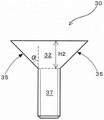
Fig. 3 is a schematic sectional view showing a screw.
Fig. 4 is a schematic cross-sectional view for explaining the thickened surface in the "form of the thick-walled electrode" (fig. 4 (a): the thickness of the electrode is equal to or larger than the size of the head of the countersunk head screw, and fig. 4 (b): the thickness of the electrode is equal to the size of the head of the countersunk head screw).
Fig. 5 is a schematic cross-sectional view for explaining the thickened surface in the "form of the thin-plate electrode bent to increase the thickness" (fig. 5 (a): the thickness increase of the electrode is the same as the size of the head of the countersunk head screw, and fig. 5 (b): the thickness increase of the electrode is the same as the size of the head of the countersunk head screw and is provided with a spacer).
Fig. 6 is a schematic cross-sectional view for explaining a close contact state preferred for thickening of the present invention, in comparison with "thin electrodes".
Fig. 7 is a schematic cross-sectional view showing a preferred example of the "form of the thick electrode".
Fig. 8 is a schematic cross-sectional view for explaining the effectiveness of the specific example of fig. 7.
Fig. 9 is a schematic perspective view showing an exemplary form of the manufacturing apparatus of the present invention.
FIG. 10 is a schematic cross-sectional view showing the form of the plating electrode of the present invention having grooves for fixing or stabilizing the electrode member to the base (FIG. 10 (a): no spacer, FIG. 10 (b): spacer, and FIG. 10 (c): use of a countersunk screw having a special shape).
Fig. 11 is a schematic cross-sectional view for explaining a manner of manufacturing a continuous metal foil by electroplating.
Description of the reference numerals
10-an electrode part; 10' -a singulated sub-electrode; 10A-thick-walled electrode; 10B-thin plate electrode; 12-side portions of the electrode parts; 15-thickened surface; 20-a substrate; 30-a screw; 40-space (isolated space); 35-tapered sides of screws; 60-a liner; 100-an electrode for electroplating; 200-a counter electrode; h1-the vertical distance dimension from the thickened face to the contact level with the substrate; h2 — conical height dimension of screw.
Detailed Description
The present invention will be described in detail below with reference to an electrode for plating and an apparatus for producing an electrolytic metal foil. Although the description will be given with reference to the drawings as necessary, the drawings are only schematic and exemplary for understanding the present invention, and the appearance, size ratio, and the like may be different from those of the actual object.
The expression "cross-sectional view angle" used in the description of the present invention corresponds to a cross-sectional view taken along the thickness direction of the plating electrode, and substantially corresponds to a view in which an object is viewed from the side. In other words, the "cross-sectional view angle" may correspond to a view taken through a plane normal to the rotation axis of the cathode drum paired with the anode for plating. The "upper side (or upper side)" used directly or indirectly as the electrode for plating according to the present invention means a direction toward the counter electrode (i.e., the drum-shaped electrode) in use, and the opposite direction corresponds to the "lower side (or lower side or bottom side)".
Electrode for plating according to the invention
The electrode for plating of the present invention is an electrode for producing an electrolytic metal foil. The plating electrode can be said to be an electrode for electroforming, and can be referred to as an "electroforming electrode" or the like. The term "electrolytic metal foil" as used herein means a metal foil produced by the principle of electroplating. Examples of the electrolytic metal foil include: the metal foil includes at least one selected from the group consisting of copper, nickel, and iron. A typical example is a copper foil.
As shown in fig. 1 (a) and (B), the plating electrode 100 of the present invention is an electrode used to face a drum-shaped counter electrode 200. According to a preferred embodiment of the metal foil production, the plating electrode 100 of the present invention corresponds to an "anode", and the counter electrode 200 corresponds to a "cathode". In the production of an electrolytic metal foil, an electric current is passed between the anode and the cathode, and a metal foil (more precisely, a metal layer which is a precursor of the metal foil) is formed on the cathode by electrolytic deposition. For example, the plating electrode used as the anode is preferably a so-called insoluble anode. In the case of an insoluble anode, the plating metal component is not supplied by dissolution of the anode, but a component originally contained in the electrolytic solution of the electrolytic bath is used as a supply source of the plating metal component.
The counter electrode as the cathode is provided in a drum shape as a whole so as to be rotatable. The term "drum" as used herein means: the counter electrode has a cylindrical shape or a substantially cylindrical shape which facilitates continuous production of the metal foil. On the other hand, the electrode as the anode is preferably disposed so as to surround a part of the drum-shaped cathode while being spaced apart from the drum-shaped cathode. That is, the plating electrode of the anode of the present invention may have a form curved along at least a part of the drum contour in its cross-sectional view. As can be seen from the illustrated form, the electrode 100 for electrolytic metal foil production has an arc shape as a whole in a cross-sectional view.
The electrode for plating of the present invention is composed of at least an electrode member and a base on which the electrode member is mounted. That is, as shown in fig. 1 (a) and (B), the plating electrode 100 has an electrode member 10 directly opposed to the counter electrode 200, and is configured to have a base 20 for fixing the electrode member. The electrode member 10 is a member that substantially functions as an anode at the time of electroforming, and preferably functions as an insoluble anode.
The electrode for plating of the present invention is characterized in that the electrode parts have different surface levels. Specifically, in the plating electrode of the present invention, the electrode member has a thickened surface as a surface facing the drum-shaped counter electrode. Since the thickened surface is a surface having a surface level (i.e., the height of the surface of the electrode) increased, the electrode for plating according to the present invention has the following features: the surface level of the electrode member, particularly the level of the surface directly opposite to the paired cathode drums (i.e., the upper surface level), is high.
As is clear from the above description, the "thickening surface" as used herein in a broad sense means substantially: the surface level of the plating electrode is increased so as to be closer to the counter electrode. "thickened area" means in a narrow sense essentially: the plating electrode has a configuration in which the upper main surface level (the level of the main surface on the opposite side of the bottom main surface directly opposed to the substrate) of the electrode member is increased so as to be closer to the counter electrode. Therefore, the "thickened surface" in the present invention may also be referred to as "raised horizontal surface" or "raised surface" or the like. In the case of the example, the thickened surface is a surface which is located at a distance of, for example, more than 2mm, preferably more than 3mm (for example, more than 5 mm) from the surface of the base (the surface of the base to which the electrode member is attached) in a state where the electrode member is attached to the base. The upper limit of the distance is not particularly limited, and is, for example, 30mm, 20mm, 15mm, 10mm, 8mm, or 5 mm.
Examples of the form in which the electrode member has the "thickened surface" include the following forms: as shown in fig. 1 (a), the electrode member 10 has a solid thick electrode form. Alternatively, the following embodiments are possible: as shown in fig. 1 (B), the electrode member 10 is a thin plate electrode, and the thin plate electrode is curved so as to increase in thickness. In the former case, the upper surface of the thick electrode corresponds to a "thickened surface" due to the large thickness of the solid thick electrode, and in the latter case, the upper surface of the thin electrode corresponds to a "thickened surface" due to the curved form in which the thickness of the thin electrode is increased.
As shown in fig. 1 (a) and (B), the plating electrode 100 preferably further includes a screw 30 for attaching the electrode member 10 to the base 20. That is, the plating electrode 100 of the present invention is preferably configured to have the screw 30 as a member for fixing the electrode member 10 to the base 20. Further, as shown in fig. 2 (a) and (B), the screw 30 preferably has a tapered side surface 35. In this case, it is preferable that the side surface portion 12 (fig. 2 (a)) or the thickened surface 15 (fig. 2 (B)) of the electrode member 10 has a shape complementary to the tapered side surface 35 of the screw 30. This improves the integrity of the electrode member and the screw, and enhances the integrity of the entire electrode member as a plating electrode. In addition, in a certain aspect, due to such a complementary relationship, a suitable electrode surface with no gap is obtained, and suitable heat dissipation is achieved by a screw (the "heat dissipation" will be described later).
As shown in fig. 3, the screw 30 is composed of at least a head portion 32 and a screw portion 37, and a side surface 35 of the head portion 32 is preferably tapered. Specifically, in the screw 30, the head portion 32 is preferably gradually reduced in width dimension toward the lower side (i.e., toward the threaded portion 37). The side surface portion 12 of the electrode member 10 is preferably complementary in shape to the screw head 32 having the tapered side surface 35 (see fig. 2 a). More preferably, in a state where the electrode member 10 is attached to the base 20, the side surface portion 12 of the electrode member 10 is not in contact with the threaded portion 37 of the screw 30, but is in close contact complementarily with the tapered side surface 35 of the head 32 of the screw 30. Similarly, as shown in fig. 2 (B), a portion 15A of the thickened surface 15 of the electrode member 10 is preferably complementary in shape to the screw head 32 having the tapered side surface 35. More preferably, in a state where the electrode member 10 is attached to the base 20, the portion 15A of the thickened surface 15 of the electrode member 10 is not in contact with the threaded portion 37 of the screw 30, but is in close contact complementarily with the tapered side surface 35 of the head 32 of the screw 30.
The electrode member in the plating electrode of the present invention has a "thickened surface" which increases the electrode surface level. For example, the vertical distance from the thickened surface to the "contact level between the electrode member and the base" in the electrode member is a taper height dimension equivalent to or larger than the tapered side surface of the screw. In the embodiment shown in fig. 4 and 5, the vertical distance H1 from the thickened surface 15 to the "contact level between the electrode member 10 and the base 20" may be substantially the same as or larger than the taper height H2 of the screw 30 with respect to the thickened surface 15. As is clear from the description, the term "perpendicular" used in the present specification means: the direction is normal or perpendicular to the thickening surface (particularly, the thickening surface of the non-bent portion).
In the description of the embodiment of fig. 4 (a) and (b), the shortest distance dimension H1 from the upper surface of the solid thick electrode 10A to the surface of the thick electrode 10A in contact with the base 20 is equal to or greater than the taper height dimension H2 of the screw 30. In the form of fig. 5 (a) and (B), the shortest distance dimension H1 from the level of the upper surface of the thin plate electrode 10B having a curved form with an increased thickness to the level of the point 18 where the thin plate electrode 10B contacts the base 20 may be substantially the same as the taper height dimension H2 of the screw 30.
The "thickened surface" having such dimensional characteristics will preferably contribute to the inter-electrode distance between the anode and cathode in the metal foil fabrication. That is, the distance between the electrodes can be further reduced by the "thickened surface" of the electrode member, and the electrolytic cell can be operated in a state where the voltage of the electrolytic cell is low. Therefore, the power cost in manufacturing the metal foil can be reduced. Further, since the inter-electrode distance can be further reduced, the current distribution of the plating electrode can be more easily made uniform, and the occurrence of defects in the manufactured metal foil can be reduced.
The plating electrode of the present invention can have a form characterized by a cross-sectional profile of a side portion of the electrode member or a cross-sectional profile of a thickened surface due to the "thickened surface". In a preferred embodiment, the electrode member is curved in the outline of the side surface portion or the thickened surface in the cross-sectional view of the electrode member.
More specifically, as shown in fig. 4 (a), the side surface portion 12 (particularly, the side surface portion 12 directly opposed to the screw) of the solid thick-walled electrode 10A may have a curved cross-sectional contour. As shown in fig. 5 (a), a part 15 '(particularly, a part 15' adjacent to the screw top surface) of the cross-sectional profile of the thickened surface 15 of the thin-plate electrode 10B having a three-dimensional shape with an increased thickness may be curved. Such a bent form is obtained due to a higher level of "thickened surface", and therefore can be said to be a feature that contributes more favorably to the reduction of the distance between the anode and the cathode in the production of the metal foil.
The plating electrode of the present invention is preferably used together with a screw, and therefore has a suitable mounting form for the electrode member. For example, in a state where the electrode member is attached to the base body by a screw, the top surface of the screw is flush with the thickened surface of the electrode member. In the embodiment shown in fig. 4, the upper surface level of the solid thick electrode 10A may be substantially the same as the top surface level of the screw 30 (the upper side surface level of the head). In the embodiment shown in fig. 5, the upper surface level of the thin plate electrode 10B having the bent shape with the increased thickness may be substantially the same as the top surface level (upper side surface level of the head) of the screw 30. By such "flush", a smoother electrode surface can be obtained. As can be seen from fig. 4 and 5, in the present invention, due to the "thickened surface": the vertical distance H1 from the thickened face to the contact level with the base in the electrode part is the conical height dimension H2 of the screw 30 or greater, and the top face of the screw 30 is flush with the thickened face of the electrode part 10. Such a feature is also obtained due to a higher level of "thickened surface", and therefore can be said to be a feature that contributes more favorably to the reduction of the distance between electrodes in electroforming.
The "electrode member", "base body", and "screw" in the plating electrode of the present invention will be described in detail below.
As described above, the electrode member is a portion that substantially functions as an anode at the time of electroforming, and is preferably an insoluble anode. The material of the electrode member is not particularly limited, and may be a valve metal (バルブ metal). More specifically, the electrode member may be configured to: containing at least one metal selected from the group consisting of tantalum, niobium, titanium, hafnium, zirconium, tungsten, bismuth and antimony. These are merely examples, and the electrode member of a preferred embodiment contains titanium or a titanium alloy from the viewpoint of corrosion resistance and versatility.
The electrode member has a "thickened face" from which the vertical distance dimension to the contact face or contact level with the substrate (i.e. "H1" in fig. 4 and 5) is preferably greater than 2mm, more preferably greater than 3 mm. The upper limit of the vertical distance is not particularly limited, and may be 30mm, 20mm, 15mm, 10mm, 8mm, or 5mm, for example, from the viewpoint of preventing short-circuiting.
Further, the surface of the electrode part may contain an electrode catalyst. For example, the surface of the electrode member may be coated with a platinum group metal or an oxide thereof. That is, the electrode catalyst may be provided on the thickened surface of the electrode member, and the electrode catalyst may be configured such that: at least one platinum group metal selected from the group consisting of palladium, rhodium, ruthenium, platinum, iridium and osmium and/or an oxide of these platinum group metals. In the case where such an electrode catalyst layer is provided, the catalyst layer may substantially constitute the surface of the thickened surface. Although only one example is shown, a catalyst containing iridium and tantalum may be used as an electrode member having a suitable form.
The base is an electroformed member for fixing the electrode member, and is preferably made of a metal material. For example, such an electrode base may be configured to contain a valve metal. That is, the substrate for fixing the electrode member may be configured such that: containing at least one metal selected from the group consisting of tantalum, niobium, titanium, hafnium, zirconium, tungsten, bismuth and antimony. Although exemplified, the base material of a preferred embodiment contains titanium or a titanium alloy. This is because titanium or a titanium alloy is preferable from the viewpoint of corrosion resistance and the like. The thickness of the substrate is not particularly limited as long as it contributes to the fixation of the electrode member used for electroforming, and may be, for example, about 10mm to 40 mm. In addition, as is clear from the embodiment shown in FIG. 9, the substrate 20 may constitute at least a part of the wall of the electrolytic cell 50. For example, the inner wall of the tank that directly contributes to the accumulation of the electrolyte may be curved (in particular, arc-shaped in cross-sectional view), and at least a part of the curved inner wall of the tank may serve as the base.
The screw is used for fixing the electrode member and the base to each other, and may be made of a metal material. For example, the screw may be constructed to contain valve metal. That is, the screw may be configured to: containing at least one metal selected from the group consisting of tantalum, niobium, titanium, hafnium, zirconium, tungsten, bismuth and antimony. Although the above embodiments are merely illustrative, a screw of a preferred embodiment contains titanium or a titanium alloy from the viewpoint of corrosion resistance and/or general versatility.
As shown in fig. 3, the screw 30 is composed of at least a head portion 32 and a screw portion 37, and a side surface 35 of the head portion 32 is preferably tapered. The taper angle α shown in fig. 3 is preferably 10 ° to 80 °, more preferably 20 ° to 70 °, and still more preferably 30 ° to 60 °. The tapered side can be provided, for example, by machining. Alternatively, a commercially available countersunk head screw may be used as it is. The height dimension H2 (see fig. 3) of head 32 provided with tapered side surfaces 35 should facilitate the thickened surface of the present invention, which may be larger than the prior art. That is, a screw of a suitable form may have a head with a height dimension that is generally recognized by those skilled in the art (particularly those skilled in the art of electrolytic metal foil manufacture). For example, the height dimension H2 of head 32 is greater than 2mm, preferably greater than 3 mm. The upper limit of the height of the screw head is not particularly limited, and may be, for example, 30mm, 20mm, 15mm, 10mm, 8mm or 5 mm.
The plating electrode of the present invention can be realized in various forms. Typically, the above-described "thick-walled electrode configuration" and "thin-plate electrode configuration with increased thickness and curvature" can be realized.
(form of thick-walled electrode)
In this embodiment, as shown in fig. 4, the electrode member 10 is a solid thick electrode 10A. That is, an electrode component is not an electrode having a thickness that is considered to be thin by those skilled in the art of electroforming (particularly, production of electrolytic metal foil), but an electrode having a thickness that is considered to be large by those skilled in the art. For example, the thickness of the solid thick-walled electrode 10A may be a taper height dimension equivalent to or larger than the arrangement portion of the tapered side face of the screw. In other words, the thickness of the solid thick-walled electrode may be greater than or equal to the height dimension of the screw head. Further, the thickness of the thick-walled electrode can obtain the strength of fixing to the base body by the setting portion of the tapered side surface of the screw. This means that: in order to obtain strength for fixing to the base by the tapered side surface of the screw, the thickness of the solid thick electrode is preferably 50% or more of the height H2 of the screw head 32, for example. That is, the thickness of the solid thick-walled electrode can obtain strength capable of fixing or attaching the thick-walled electrode to the base body by the support of the tapered side surface of the screw (in this case, the thickness of the solid thick-walled electrode may be, for example, 50% or more of the height dimension H2 of the screw head 32).
The thickness of such a thick-walled electrode preferably contributes to realizing a "thickened surface" of the electrode member, and more preferably contributes to the inter-electrode distance between the anode and the cathode in the production of the metal foil. That is, the distance between the electrodes can be further reduced by the thickness of the thick electrode, and the electrolytic cell can be operated in a state where the voltage of the electrolytic cell is low. Therefore, the power cost in manufacturing the metal foil can be reduced. In addition, not only can the distance between the electrodes be further reduced, but also the current distribution on the plating electrode at the time of energization can be made more uniform by increasing the thickness of the electrode, and the occurrence of defects in the metal foil to be produced can be reduced.
Although illustrated only, the specific thickness of a solid thick-walled electrode is for example greater than 2mm, preferably greater than 3 mm. The upper limit of the solid thick electrode is not particularly limited, and may be, for example, 30mm, 20mm, 15mm, 10mm, 8mm, or 5 mm. As generally recognized by those skilled in the art (particularly those skilled in the art of electrolytic metal foil manufacture), such a thickness is large as an anode used in the manufacture of electrolytic metal foils. Whereas the thickness of the prior art electrode is about 1mm, the solid thick-walled electrode of the present invention is at least two times, preferably three times, greater than the prior art plated electrode, or 2 to 30 times, preferably 3 to 20 times (e.g., 3 to 10 times, 3 to 8 times, or 3 to 5 times) greater than the thickness of the prior art electrode. Such an electrode thicker than the conventional one has not been practically used as an anode electrode for electrolytic metal foil in the past because it is considered difficult to machine (in particular, to machine a hole for a screw) by those skilled in the art. In this respect, it can be said that the present invention is accomplished by the application of a larger electrode thickness in a fruit and vegetable manner without being limited to such conventional knowledge.
In a preferred embodiment, in a state where the thick electrode 10A is attached to the base 20 by the screw 30, the thick electrode 10A and the base 20 are in contact with each other over the entire surface, and in particular, they are in close contact with each other (see fig. 4). As is clear from fig. 4, the thick electrode 10A is in an unbent form, and the lower main surface of the thick electrode 10A is in close contact with the upper main surface of the substrate 20. Preferably, the lower main surface of the thick electrode and the upper main surface of the base are in close contact with each other in a substantially gapless liquid-tight state. This is a significant feature compared to when the electrode member is a relatively thin electrode. This is described in detail below. If the electrode member is not thick but thin, there is a risk that the thin electrode member will be bent to an uneven degree due to the point fastening of the screw fixation when the electrode member is fixed to the base by the screw (see "thin electrode case" in fig. 6). Thus, a thin electrode member mounted on the base may form a minute gap with the base (even if drawn in close contact in the normally illustrated form, the electrode member actually has a minute gap or is likely to have a minute gap). In this respect, in the present invention, the electrode member provides high rigidity due to the large thickness of the thick-walled electrode, and the electrode member is less likely to be bent due to the point fastening by the screw (see "present invention" in fig. 6). Therefore, the lower main surface of the thick electrode 10 and the upper main surface of the substrate 20 can be favorably in close contact with each other, and preferably can be in close contact with each other in a liquid-tight manner with substantially no gap. This means that: when the electrode for electroplating of the present invention is used, the current distribution is more easily uniformized, and the occurrence of defects in the manufactured metal foil is easily reduced. In the case of the thick electrode 10A, the current distribution during the energization is good due to the originally large electrode thickness (electrode thicker than the conventional thin electrode), and therefore, more uniform plating can be realized. Further, in the case of the thick-walled electrode 10A, the thick-walled electrode can be brought into a state in which the thickness side surface and the head side surface of the screw are in close contact with each other in a state in which the electrode member is mounted on the base (see "the present invention" in fig. 6), and in this respect, the current distribution at the time of energization can be made good and uniform plating can be easily achieved.
In addition, in the case where the electrode member is a solid thick electrode, the side surface of the electrode and the screw may have a peculiar shape relationship due to the thickness thereof. Specifically, as shown in fig. 4, the thick-walled side surface 12 of the thick-walled electrode 10A may include a shape complementary to the tapered side surface 35 of the screw 30. That is, the side surface contributing to the thickening of the thick-walled electrode 10A in the non-bent state and the head-side surface of the screw 30 have shapes complementary to each other, and the thick-walled electrode and the head-side surface of the screw are in close contact with each other in a state where the electrode member is mounted on the base. In such an embodiment, there is an advantageous effect that heat can be satisfactorily dissipated through the side surface of the thick electrode. Specifically, since the temperature of the electrolyte solution rises due to the energization at the time of electroforming, there is a possibility that the temperature rise needs to be suppressed, and in the present invention, heat can be satisfactorily radiated to the outside of the groove by the thick-walled electrode and the screw in close contact with the side surface thereof.
The thick electrode used for the plating electrode of the present invention is obtained by degreasing and cleaning a conductive base material with an alkali or an organic solvent, and then subjecting the base material to a mechanical surface treatment such as a blasting treatment, a chemical surface treatment with an acid or an alkali, or a surface treatment combining both the mechanical treatment and the chemical treatment, thereby coating and firing an electrode catalyst on a substrate. The electrode catalyst is preferably a mixed oxide of a platinum group metal or an oxide thereof and an oxide of one or more metals selected from the group consisting of valve metals (titanium, tantalum, niobium, tungsten, zirconium) and tin. Typical examples thereof include iridium-tantalum mixed oxide and iridium-tantalum-titanium mixed oxide. The coating layer of the electrode active material can be prepared by sequentially applying, drying, and firing the solution containing the electrode active material as described above, and the steps from applying to firing can be repeatedly performed until a predetermined amount of the catalyst is reached, thereby obtaining an insoluble anode. The thick-walled electrode thus obtained is provided with a hole for a screw by machining, chemical etching or the like, and the thick-walled electrode is mounted on the base body by the screw through the hole, whereby a plating electrode for use in electrolytic metal foil production can be obtained. Before applying the solution containing the electrode active material as described above, a hole serving as a screw hole may be provided in the conductive base material of the thick electrode by machining, chemical etching, or the like.
A preferred specific example of the case where the electrode member is a solid thick electrode will be described with reference to fig. 7. In this specific example, a counterbore 26 is provided to the base 20. The counterbore 26 may be in the form of a tapered recess, and therefore, the base 20 may be provided with a recess having the same form as a screw as a whole as illustrated (the "counterbore" in the present specification may be referred to as a "base recess" or a "tapered recess", for example). While the counterbore 26 is thus provided, the counterbore 26 is not completely submerged by the screw 30 due to the "solid thick-walled electrode". That is, in a preferred example, the screw 30 is disposed so as to be spaced apart from the counterbore surface 26 '(the bottom surface 26' shaped as the counterbore 26) of the base 20 in a state where the screw head 32 is hooked on the tapered side surface of the electrode member 10. This means that: in a state where the electrode member 10 is attached to the base body 20, a space 28 (particularly, a conical space 28 formed by a conical counterbore) is provided in a region surrounded by the screw 30 (particularly, the screw head 32), the electrode member 10, and the base body 20. As can be seen from the illustration, the combination of the screw head 32 and the electrode member 10 in close contact with each other is integrated with the base 20 while leaving or providing a space 28 (additionally, a space 29 is also provided in the region of the screw hole of the base) in the counterbore forming region. In such an embodiment, the top surface of the screw 30 is preferably flush with the thickened surface 15 of the electrode member 10. Additionally, the thick-walled side 12 of the thick-walled electrode 10A may comprise a shape complementary to the tapered side 35 of the screw 30. The thickness of the solid thick-walled electrode 10A may be a taper height dimension corresponding to the portion where the tapered side surface of the screw is provided or may be larger than the taper height dimension (however, as long as the solid thick-walled electrode 10A is in a form in which the screw head is hooked to the tapered side surface of the electrode as described above, the thick-walled electrode 10A may be smaller than the taper height dimension as shown in lower bracket of fig. 7. Although the example is given, the thickness of the electrode member 10 of the embodiment of fig. 7 may be, for example, about 3 to 8 mm.
The advantages of the present invention in which the counter bore 26 is provided in the base body 20 will be described below in comparison with the case of a thinner electrode member. As shown in fig. 8, the electrode member 11 (for example, an electrode member made of titanium and having a thickness of about 1 mm) which is relatively thin is practically hard to bend in an acute angle shape at the screw engagement portion, and there is a problem that the contact is restricted. That is, in the thin electrode member 11 bent in this manner, the contact point of the screw engagement portion may be limited (for example, limited to a portion surrounded by a dotted line shown in fig. 8), and the contact with the base may not be preferable. Therefore, it can be said that the thinner electrode member still has room for improvement in terms of current distribution at the time of energization. In this respect, in the case of the solid thick electrode of the present invention, as is apparent from the configuration shown in fig. 7, the contact points of the screw engaging portion are substantially uniform, and therefore, a preferable state can be obtained in terms of current distribution at the time of energization.
Further, the embodiment of the present invention shown in fig. 7 is preferable in terms of mounting the electrode member 10 and the base body 20 to each other. Specifically, since the space 28 is positioned below the screw 30 (particularly the screw head 32), the screw can be more strongly tightened to be displaced further downward, and the lower main surface of the thick electrode 10 and the upper main surface of the base 20 can be more strongly brought into close contact with each other. Preferably, the electrodes can be closely attached in a liquid-tight manner without any gap (as described with reference to fig. 6, since the thick-walled electrode has a large thickness and a high rigidity is provided by the electrode member, even if the electrode member is strongly fastened, the electrode member itself is not easily bent). Therefore, it is also easy to make the current distribution uniform in this respect, and as a result, it can be said that the occurrence of defects in the metal foil to be produced can be easily reduced.
(form of bent thin plate electrode to increase thickness)
As shown in fig. 5, the electrode member 10 in this embodiment is a thin plate electrode 10B, and particularly, is a thin plate electrode 10B that is bent to increase its thickness. That is, the thickness of the entire electrode member is increased by bending the thin-plate electrode 10B having a substantially constant thickness (that is, it can be said that the thickness of the plating electrode is increased by bending the electrode member having a constant thickness). In this form, although it is considered that the thickness of the electrode is thin for those skilled in the art of electroforming (particularly, electrolytic metal foil manufacturing), the thin electrode is a form in which the thickness is increased three-dimensionally by locally bending the thin electrode. The thickness of the thin-plate electrode 10B is 3mm or less, preferably 2mm or less, for example, 1.5mm or less or 1.0mm or less (the lower limit is not particularly limited, and may be, for example, about 0.2mm, 0.5mm or 0.7 mm) because of the "thin plate". In spite of such a thin thickness, in the case of a thin plate electrode which is partially bent to increase the thickness three-dimensionally, the dimension between the uppermost level and the lowermost level thereof is preferably the taper height dimension of the screw or larger than the same. Alternatively, the maximum three-dimensional thickness of the sheet electrode bent so as to increase the thickness as a whole may be equal to or greater than the height of the screw head.
Since the thickness is increased three-dimensionally by partial bending, an isolation space is formed between the thin plate electrode and the base in a state where the electrode member is attached to the base by a screw. As is apparent from the embodiment shown in fig. 5, the non-bent portion of the thin plate electrode 10B and the base 20 are spaced from each other, thereby forming a "thickened surface" of the electrode member 10. In other words, in the thin plate electrode bent to increase the thickness as a whole three-dimensionally, the space between the thin plate electrode and the base suitably contributes to the "thickened surface", and has an advantageous effect on the distance between the anode and the cathode in the production of the metal foil. Therefore, in the embodiment shown in fig. 5, the inter-electrode distance can be further reduced, and the operation can be performed in a state where the voltage of the electrolytic cell is lowered. That is, the power cost at the time of manufacturing the metal foil can be reduced.
Since the "thickened surface" is a curved shape in which the thickness of the thin-plate electrode is increased three-dimensionally, the sum of the thickness of the thin-plate electrode (the thickness of the thin-plate electrode itself) and the thickness of the isolation space is preferably a taper height dimension corresponding to the portion of the screw where the tapered side surface is provided or larger in a state in which the electrode member is attached to the base body by the screw. The sum of the thickness of the thin plate electrode in the curved form in which the thickness is increased three-dimensionally (the thickness of the thin plate electrode itself) and the thickness of the isolation space may be equal to or greater than the height of the screw head.
Although the embodiment of the thin plate electrode that is curved to increase the thickness three-dimensionally is merely illustrative, the distance between the surface of the substrate and the thickness increasing surface of the thin plate electrode (i.e., the upper main surface of the electrode) is, for example, greater than 2mm, preferably greater than 3 mm. The upper limit of the distance is not particularly limited, and may be, for example, 30mm, 20mm, 15mm, 10mm, 8mm or 5 mm. Although the example is given only, when the thickness of the thin plate electrode itself is, for example, 1mm or less, the gap size of the separation space between the thin plate electrode and the base (the size in the direction along the thickness of the non-bent portion of the electrode) may be 1mm or less, and preferably 2mm or less (the upper limit value thereof may be, for example, 29mm, 19mm, 14mm, 9mm, 7mm, or 4 mm).
The thin plate electrode having a three-dimensionally increased thickness used for the plating electrode of the present invention can be obtained, for example, by: an electrode having a small thickness, which is generally used as an anode electrode of an electrolytic metal foil, is locally bent or locally recessed by an external force. The thus obtained thin plate electrode having an increased thickness is provided with a screw hole (particularly, a screw hole at a portion of a local bent portion or a concave portion) by machining or chemical etching, and the thin plate electrode is attached to a base body by a screw through the screw hole, whereby the plating electrode of the present invention can be obtained for use in the production of electrolytic metal foil. In the case where the formation of the screw hole involves a local external force, a local bend or a local recess may be formed when the screw hole is formed.
The spacer 60 may be provided in the isolation space 40 in a form of a thin plate electrode that is bent to increase the thickness three-dimensionally (see fig. 5 (b)). That is, the spacer 60 that partially occupies the space 40 between the non-bent portion of the sheet electrode 10B and the base body 20 may be provided in a state where the electrode member 10 is attached to the base body 20 by the screw 30. By providing the spacer, the shape in which the thickness of the thin plate electrode increases can be more easily and favorably maintained with the lapse of time at the time of electroforming.
The material of the spacer is not particularly limited as long as it can maintain the "isolation space". Thus, the gasket may comprise a metallic material, a resin material and/or a ceramic material. In order to more easily maintain the "isolated space", it is preferable to have a certain degree of rigidity. As one illustration, the gasket may be a solid metal block. The pad may have a form of a so-called "steel ball (japanese: かねたわし)" and may have a moderate elastic characteristic. When the material of the spacer is a metal material, it is preferable that a heat radiation path can be formed through the thin plate member, the spacer, and the base, and heat generated by the electrolyte at the time of electroforming can be radiated to the outside of the groove through the spacer. The method of fixing the spacer is not particularly limited. The fixing may be performed by a separate means, but the spacer may be fixed by a clamping force generated between the non-bent portion of the sheet electrode and the base by a screw.
In the thin plate electrode, the thickness of which is increased three-dimensionally by bending in a state where the electrode member is attached to the base by the screw, the non-bent portion is separated from the base, but the bent portion is preferably in contact with the base. As can be seen from the configuration shown in fig. 5 (B), for example, the bent portion 10B of the thin plate electrode 10B bent to increase the thickness thereof three-dimensionally Bending of Preferably with the tapered side surface 35 of the screw. Particularly preferably, the bent portion 10B of the thin plate electrode 10B contributes to a three-dimensional increase in thickness Bending of The side surfaces 35 of the head 32 of the screw 30 are in close contact with each other in a liquid-tight state. This is because the bent portion of the thin plate electrode can radiate heat well. Specifically, since the temperature of the electrolyte solution rises due to the energization at the time of electroforming, there is a possibility that the temperature rise needs to be suppressed, and heat can be satisfactorily dissipated to the outside of the groove by the bent portion of the thin plate electrode and the screw closely contacting the bent portion. Further, as shown in fig. 5 (B), the bent portion 10B of the thin plate electrode Bending of In contact with the screw 30 and also in contact with the base body 20. Therefore, the bent portion of the thin plate electrode can satisfactorily dissipate heat generated by the electrolyte at the time of electroforming to the outside through not only the screw but also the base. Accordingly, the bent portion of the thin plate electrode may also be referred to as a plated heat sink portion.
The plating electrode of the present invention may have a form in which the electrode member is singulated, regardless of the "form of the thick-walled electrode" and the "form of the bent thin-plate electrode having a large thickness" described above. That is, the electrode member 10 may be formed by a combination of a plurality of sub-electrodes 10 'that are formed as separate pieces, and the sub-electrodes 10' may be attached to the base 20 (see fig. 9). In this case, the sub-electrodes 10' are fixed to the base 20 by screws 30.
In such a configuration of the sub-electrode, when the catalyst activity of the electrode is deactivated or peeling occurs or a failure such as corrosion or damage occurs to an electrode member, only the intended sub-electrode can be replaced. That is, in the form of the sub-electrodes which are singulated, the convenience in maintenance, repair, and the like of the plating electrodes is improved.
Preferably, each sub-electrode 10' has a form along the curved shape of the base body. In other words, each sub-electrode 10' preferably has a shape that is bent along the base when it is fixed to the base (or when it is attached to the base). The electrode member obtained by combining the plurality of sub-electrodes preferably has a configuration in which the drum contour of the counter electrode and the separation distance of the anode are kept equal as a whole. Since the sub-electrode 10 ' obtained by singulating the thick-walled electrode 10A has a shape of a curved shape along the base (see fig. 9), the sub-electrode 10 ' can be brought into close contact with the base 20 without a gap by fixing the sub-electrode 10 ' to the base 20 with the screw 30. However, in the case where the sub-electrode 10 ' is fixed to the base 20 by the screw 30 so that the sub-electrode 10 ' can deform following the shape of the base, the thin plate electrode 10B having the small thickness of the sub-electrode 10 ' does not need to have a shape along the curved shape in advance (for example, each sub-electrode may have a non-curved shape or a flat shape).
Apparatus for producing electrolytic Metal foil according to the invention
The apparatus of the present invention is an apparatus for manufacturing an electrolytic metal foil, and is configured to have at least the above-described electrode for plating. That is, the electrolytic metal foil manufacturing apparatus of the present invention includes: the plating electrode 100 as an anode and the drum-shaped counter electrode 200 as a cathode (see fig. 9).
In the apparatus of the present invention, the plating electrode used as the anode is composed of at least an electrode member and a base body on which the electrode member is mounted, and the electrode member of the anode has a "thickened surface" as a surface facing the drum-like counter electrode of the cathode.
The manufacturing apparatus of the present invention has a positional relationship in which the plating electrode as the anode is closer to the counter electrode as the cathode or closer to the counter electrode due to the "thickened surface". Therefore, when the manufacturing apparatus of the present invention is used, the electrolytic cell can be operated in a state where the voltage of the electrolytic cell is low, and the power cost can be reduced. Further, by increasing the thickness of the conductive base material as the anode, it becomes easier to make the current distribution on the plating electrode uniform during energization, and it is also possible to reduce the occurrence of defects in the metal foil to be produced. Although the electrolytic metal foil manufacturing apparatus of the present invention is described by way of example only, the separation distance between the anode and the cathode (the distance between the proximal surfaces of the two electrodes) is preferably 5 to 25mm, more preferably 5 to 20mm, and still more preferably 6 to 15mm (for example, about 6 to 10 mm).
Electroplating is performed when the metal foil is manufactured. Therefore, the apparatus of the present invention further comprises an electrolytic cell. In this electrolytic cell, "an electrode for plating as an anode" and "a drum-shaped counter electrode as a cathode" are arranged at a predetermined distance from each other. At least a portion of the walls of the electrolytic bath 50 may constitute the base 20 of the plating electrode. That is, a part of the wall of the electrolytic bath is curved in an arc shape, so that the curved wall can also serve as a base for the plating electrode.
In the electrolytic cell, a drum-shaped counter electrode is provided as a cathode so as to be rotatable. That is, the cathode is disposed in the electrolytic cell as a rotating drum. Specifically, it is preferable to dispose the cathode so that the substantially lower half of the rotary drum is immersed in the electrolyte (i.e., plating solution) in the electrolytic bath. The drum-like cathode itself may be a cathode commonly used in the manufacture of electrolytic metal foils. In the manufacture of the metal foil, the drum of the cathode is rotated, and electrodeposition is performed while it is in contact with the electrolyte. As the drum rotates, a portion of the cathode drum in contact with the electrolyte is exposed to the air, at which point the electrodeposited layer may be mechanically stripped from the drum surface. Thereby, a desired metal foil can be obtained. Since the metal foil can be continuously obtained, an appropriate reel unit for winding it may also be provided.
The manufacturing apparatus of the present invention is configured to further include a bus bar for supplying power to the electrode. For example, the bus bar may be attached to the electrode member and/or the base of the plating electrode. By using such a bus bar, a direct current can be passed between the anode and the cathode, and a desired electroforming can be performed. In addition, the base body or the like may have a supply port (e.g., a gap portion) for supplying the electrolytic solution. The consumed plating component can be appropriately replenished through such a supply port.
Further details of the manufacturing apparatus of the present invention, and other matters such as more specific embodiments are described in the above-mentioned "electrode for plating of the present invention", and therefore, the description thereof is omitted to avoid redundancy.
While various embodiments of the present invention have been described above, it should be understood that the present invention is not limited thereto, and various embodiments can be realized by those skilled in the art without departing from the scope of the present invention defined by the claims.
For example, in the present invention, as shown in fig. 10 (a) to (c), a groove 25 for fixing or stabilizing the electrode member 10 may be provided in the base 20. That is, the base 20 may be provided with the groove 25, and the groove 25 may be fitted in the "screw hole vicinity portion 19" of the electrode member 10 in a state where the electrode member 10 is attached to the base 20. In this case, the vicinity portion 19 of the electrode member 10 (particularly, the thin plate electrode 10B) is sandwiched between the screw 30 and the base 20, and therefore, fixation or stabilization of the electrode member attached to the base can be promoted. As is clear from the illustrated embodiment, the groove 25 may correspond to a counterbore in some embodiments with respect to the base 20, and therefore the embodiments illustrated in fig. 10 (a) to (c) may be considered to be suitable embodiments in which counterbores are used for fixing or stabilizing the electrode member 10 (particularly, the thin-plate electrode 10B).
As shown in fig. 10 (c), the head of the screw 30 may include a non-tapered portion. In this case, the portion of the electrode member 10 (particularly, the thin-plate electrode 10B) sandwiched between the screw 30 and the base 20 can be further increased (that is, as is apparent from the figure, the portion 19 in the vicinity of the electrode member 10(10B) sandwiched between the screw 30 and the base 20 can be further increased). Therefore, in this aspect, the fixation or stabilization of the electrode member attached to the base can be promoted.
Industrial applicability
The plating electrode of the present invention can be used in various fields where plating is performed. In particular, the present invention can be suitably used for electroforming for manufacturing a metal foil by electroplating. This is merely an example, but the electrode for plating of the present invention can be suitably used as an anode of an electrolytic device for producing a metal foil used for an electrode collector of a printed circuit material or a secondary battery.
Claims (12)
1. An electrode for electroplating, which is used for manufacturing an electrolytic metal foil,
the electrode for plating is composed of at least an electrode member and a base body on which the electrode member is mounted,
the electrode member has a thickened surface as a surface opposed to the drum-shaped counter electrode,
further comprising a screw for mounting the electrode member to the base,
the screw having a tapered side face, the side face portion of the electrode part having a shape complementary to the tapered side face,
the electrode component is a solid thick-wall electrode,
the base body is provided with a counter bore, and the combination of the screw head and the electrode component which are tightly connected leaves a space in the area of the counter bore and is integrated with the base body.
2. A plating electrode according to claim 1, wherein a vertical distance dimension from the thickened surface to a contact level with the base in the electrode member is a taper height dimension corresponding to a portion where the tapered side surface of the screw is provided or is larger than the taper height dimension.
3. An electrode for plating according to claim 1 or 2, wherein a side profile of the electrode member is curved in a cross-sectional view of the electrode member.
4. A plating electrode according to claim 1, wherein a top surface of the screw is flush with the thickened surface of the electrode member in a state where the electrode member is attached to the base by the screw.
5. The plating electrode according to claim 1, wherein a thickness of the thick-walled electrode has a strength that is fixed to the base by a portion of the screw where the tapered side surface is provided.
6. The plating electrode according to claim 1, wherein a thickness of the thick-walled electrode is equal to or greater than a taper height dimension of a portion of the screw where the tapered side surface is provided.
7. An electrode according to claim 1, wherein the thickness of the thick-walled electrode is greater than 2 mm.
8. A plating electrode according to claim 1, wherein the thick-walled electrode is in close contact with the base in a state where the electrode member is attached to the base by the screw.
9. An electrode for plating according to claim 1 or 2, wherein said electrode member is composed of a combination of a plurality of sub-electrodes formed in a single piece, and each of the sub-electrodes is attached to said base.
10. A plating electrode according to claim 9, wherein each of the sub-electrodes is bent along the base when fixed to the base.
11. A plating electrode according to claim 1 or 2, wherein the plating electrode is an anode and the counter electrode is a cathode.
12. An apparatus for manufacturing an electrolytic metal foil, comprising at least the plating electrode according to any one of claims 1 to 11.
Applications Claiming Priority (2)
| Application Number | Priority Date | Filing Date | Title |
|---|---|---|---|
| JP2017191163A JP6946911B2 (en) | 2017-09-29 | 2017-09-29 | Manufacturing equipment for plating electrodes and electrolytic metal leaf |
| JP2017-191163 | 2017-09-29 |
Publications (2)
| Publication Number | Publication Date |
|---|---|
| CN109576739A CN109576739A (en) | 2019-04-05 |
| CN109576739B true CN109576739B (en) | 2022-09-27 |
Family
ID=65919751
Family Applications (1)
| Application Number | Title | Priority Date | Filing Date |
|---|---|---|---|
| CN201811085722.6A Active CN109576739B (en) | 2017-09-29 | 2018-09-18 | Electrode for electroplating and apparatus for manufacturing electrolytic metal foil |
Country Status (4)
| Country | Link |
|---|---|
| JP (1) | JP6946911B2 (en) |
| KR (1) | KR102525857B1 (en) |
| CN (1) | CN109576739B (en) |
| TW (1) | TWI760564B (en) |
Families Citing this family (3)
| Publication number | Priority date | Publication date | Assignee | Title |
|---|---|---|---|---|
| JP7005558B2 (en) * | 2019-06-10 | 2022-01-21 | 日鉄工材株式会社 | Metal leaf manufacturing equipment |
| CN112251780B (en) * | 2020-09-07 | 2021-11-05 | 浙江大学 | Improved preparation method of flat electro-deposition copper foil |
| KR102538289B1 (en) * | 2023-02-07 | 2023-05-31 | 주식회사 웨스코일렉트로드 | Anode assembly for manufacturing electrolytic copper foil |
Citations (9)
| Publication number | Priority date | Publication date | Assignee | Title |
|---|---|---|---|---|
| JPH05171486A (en) * | 1991-12-26 | 1993-07-09 | Permelec Electrode Ltd | Method for reactivating anode for apparatus continuously producing metallic foil |
| JPH06346270A (en) * | 1993-06-10 | 1994-12-20 | Tdk Corp | Electroplating method and split insoluble electrode for electroplating |
| US5489368A (en) * | 1992-01-28 | 1996-02-06 | Permelec Electrode, Ltd. | Insoluble electrode structural material |
| CN1214088A (en) * | 1994-12-30 | 1999-04-14 | 石福金属兴业株式会社 | Compound electrode for electrolysis |
| JP2002038291A (en) * | 2001-09-03 | 2002-02-06 | Daiso Co Ltd | Anode for manufacturing metallic foil |
| CN101899699A (en) * | 2009-04-01 | 2010-12-01 | 培尔梅烈克电极股份有限公司 | Electrolyic metal foil manufacturing apparatus and a manufacturing method for an electrode of the apparatus and an electrolyic metal foil obtained by the apparatus |
| CN202482454U (en) * | 2012-02-07 | 2012-10-10 | 宝鸡天邦钛镍有限公司 | Dimensionally stable anode (DSA) integrated titanium anode for electrolytic copper foil manufacturing machine |
| JP2013204042A (en) * | 2012-03-27 | 2013-10-07 | Daiso Co Ltd | Insoluble electrode structural body and method of repairing the insoluble electrode structural body |
| CN205088315U (en) * | 2015-09-16 | 2016-03-16 | 沈阳中科惠友科技发展有限责任公司 | Thickening arc titanium anode board |
Family Cites Families (3)
| Publication number | Priority date | Publication date | Assignee | Title |
|---|---|---|---|---|
| JPH0647758A (en) | 1992-07-31 | 1994-02-22 | Olympus Optical Co Ltd | Method and apparatus for producing composite optical element |
| JP3468545B2 (en) | 1993-04-30 | 2003-11-17 | ペルメレック電極株式会社 | Electrode for electrolysis |
| JP5414257B2 (en) | 2008-12-08 | 2014-02-12 | 株式会社昭和 | Electrode for electrolysis |
-
2017
- 2017-09-29 JP JP2017191163A patent/JP6946911B2/en active Active
-
2018
- 2018-09-10 KR KR1020180107684A patent/KR102525857B1/en active IP Right Grant
- 2018-09-18 CN CN201811085722.6A patent/CN109576739B/en active Active
- 2018-09-20 TW TW107133097A patent/TWI760564B/en active
Patent Citations (9)
| Publication number | Priority date | Publication date | Assignee | Title |
|---|---|---|---|---|
| JPH05171486A (en) * | 1991-12-26 | 1993-07-09 | Permelec Electrode Ltd | Method for reactivating anode for apparatus continuously producing metallic foil |
| US5489368A (en) * | 1992-01-28 | 1996-02-06 | Permelec Electrode, Ltd. | Insoluble electrode structural material |
| JPH06346270A (en) * | 1993-06-10 | 1994-12-20 | Tdk Corp | Electroplating method and split insoluble electrode for electroplating |
| CN1214088A (en) * | 1994-12-30 | 1999-04-14 | 石福金属兴业株式会社 | Compound electrode for electrolysis |
| JP2002038291A (en) * | 2001-09-03 | 2002-02-06 | Daiso Co Ltd | Anode for manufacturing metallic foil |
| CN101899699A (en) * | 2009-04-01 | 2010-12-01 | 培尔梅烈克电极股份有限公司 | Electrolyic metal foil manufacturing apparatus and a manufacturing method for an electrode of the apparatus and an electrolyic metal foil obtained by the apparatus |
| CN202482454U (en) * | 2012-02-07 | 2012-10-10 | 宝鸡天邦钛镍有限公司 | Dimensionally stable anode (DSA) integrated titanium anode for electrolytic copper foil manufacturing machine |
| JP2013204042A (en) * | 2012-03-27 | 2013-10-07 | Daiso Co Ltd | Insoluble electrode structural body and method of repairing the insoluble electrode structural body |
| CN205088315U (en) * | 2015-09-16 | 2016-03-16 | 沈阳中科惠友科技发展有限责任公司 | Thickening arc titanium anode board |
Also Published As
| Publication number | Publication date |
|---|---|
| KR20190038325A (en) | 2019-04-08 |
| TW201920779A (en) | 2019-06-01 |
| TWI760564B (en) | 2022-04-11 |
| JP6946911B2 (en) | 2021-10-13 |
| CN109576739A (en) | 2019-04-05 |
| KR102525857B1 (en) | 2023-04-26 |
| JP2019065339A (en) | 2019-04-25 |
Similar Documents
| Publication | Publication Date | Title |
|---|---|---|
| CN109576739B (en) | Electrode for electroplating and apparatus for manufacturing electrolytic metal foil | |
| EP2236653B1 (en) | Production apparatus for electro-deposited metal foil, production method of thin plate insoluble metal electrode used in production apparatus for electro-deposited metal foil, and electro-deposited metal foil produced by using production apparatus for electro-deposited metal foil | |
| KR100391839B1 (en) | Electrolytic Composite Electrode | |
| EP2641999A1 (en) | Electrolytic copper foil | |
| US11492717B2 (en) | Manufacturing apparatus of electrolytic copper foil | |
| JP2963266B2 (en) | Insoluble electrode structure | |
| KR20190106364A (en) | Cathode drum for electrolytic deposition | |
| JP5414257B2 (en) | Electrode for electrolysis | |
| CN112064066A (en) | Metal foil manufacturing device | |
| TWI785154B (en) | Metal foil production apparatus and electrode plate mounting body | |
| CN108796591B (en) | Electrode structure | |
| KR102548837B1 (en) | An insoluble anode assembly for manufacturing an electrolytic metal foil | |
| CN110528054B (en) | Device and method for electrodepositing nickel on PCB without stopping groove | |
| JP2002038291A (en) | Anode for manufacturing metallic foil | |
| JP3416620B2 (en) | Electrolytic copper foil manufacturing apparatus and electrolytic copper foil manufacturing method | |
| KR100516484B1 (en) | Plating apparatus having a plurality of power supply and plating method using the same | |
| JP2022536258A (en) | Electrode assembly for electrochemical processes | |
| JP2002004095A (en) | Insoluble anode and power feeding method for the same | |
| KR101630980B1 (en) | Apparatus for continuous electroforming | |
| KR100727270B1 (en) | Plating electrode structure for manufacturing printed circuit board and electroplating device thereof | |
| JP2004315937A (en) | Insoluble electrode for manufacturing metal foil | |
| JPH0156153B2 (en) | ||
| JPH0762583A (en) | Electrolytic electrode | |
| JPH05339797A (en) | Soluble electrode of radial-cell electroplating device |
Legal Events
| Date | Code | Title | Description |
|---|---|---|---|
| PB01 | Publication | ||
| PB01 | Publication | ||
| SE01 | Entry into force of request for substantive examination | ||
| SE01 | Entry into force of request for substantive examination | ||
| GR01 | Patent grant | ||
| GR01 | Patent grant |