CN109383047B - Resin molding device and method for manufacturing resin molded product - Google Patents
Resin molding device and method for manufacturing resin molded product Download PDFInfo
- Publication number
- CN109383047B CN109383047B CN201810886070.XA CN201810886070A CN109383047B CN 109383047 B CN109383047 B CN 109383047B CN 201810886070 A CN201810886070 A CN 201810886070A CN 109383047 B CN109383047 B CN 109383047B
- Authority
- CN
- China
- Prior art keywords
- resin
- mold
- molding
- die
- plunger
- Prior art date
- Legal status (The legal status is an assumption and is not a legal conclusion. Google has not performed a legal analysis and makes no representation as to the accuracy of the status listed.)
- Active
Links
Images


Classifications
-
- B—PERFORMING OPERATIONS; TRANSPORTING
- B29—WORKING OF PLASTICS; WORKING OF SUBSTANCES IN A PLASTIC STATE IN GENERAL
- B29C—SHAPING OR JOINING OF PLASTICS; SHAPING OF MATERIAL IN A PLASTIC STATE, NOT OTHERWISE PROVIDED FOR; AFTER-TREATMENT OF THE SHAPED PRODUCTS, e.g. REPAIRING
- B29C70/00—Shaping composites, i.e. plastics material comprising reinforcements, fillers or preformed parts, e.g. inserts
- B29C70/04—Shaping composites, i.e. plastics material comprising reinforcements, fillers or preformed parts, e.g. inserts comprising reinforcements only, e.g. self-reinforcing plastics
- B29C70/28—Shaping operations therefor
- B29C70/40—Shaping or impregnating by compression not applied
- B29C70/42—Shaping or impregnating by compression not applied for producing articles of definite length, i.e. discrete articles
- B29C70/46—Shaping or impregnating by compression not applied for producing articles of definite length, i.e. discrete articles using matched moulds, e.g. for deforming sheet moulding compounds [SMC] or prepregs
- B29C70/48—Shaping or impregnating by compression not applied for producing articles of definite length, i.e. discrete articles using matched moulds, e.g. for deforming sheet moulding compounds [SMC] or prepregs and impregnating the reinforcements in the closed mould, e.g. resin transfer moulding [RTM], e.g. by vacuum
-
- B—PERFORMING OPERATIONS; TRANSPORTING
- B29—WORKING OF PLASTICS; WORKING OF SUBSTANCES IN A PLASTIC STATE IN GENERAL
- B29C—SHAPING OR JOINING OF PLASTICS; SHAPING OF MATERIAL IN A PLASTIC STATE, NOT OTHERWISE PROVIDED FOR; AFTER-TREATMENT OF THE SHAPED PRODUCTS, e.g. REPAIRING
- B29C45/00—Injection moulding, i.e. forcing the required volume of moulding material through a nozzle into a closed mould; Apparatus therefor
- B29C45/02—Transfer moulding, i.e. transferring the required volume of moulding material by a plunger from a "shot" cavity into a mould cavity
-
- B—PERFORMING OPERATIONS; TRANSPORTING
- B29—WORKING OF PLASTICS; WORKING OF SUBSTANCES IN A PLASTIC STATE IN GENERAL
- B29C—SHAPING OR JOINING OF PLASTICS; SHAPING OF MATERIAL IN A PLASTIC STATE, NOT OTHERWISE PROVIDED FOR; AFTER-TREATMENT OF THE SHAPED PRODUCTS, e.g. REPAIRING
- B29C70/00—Shaping composites, i.e. plastics material comprising reinforcements, fillers or preformed parts, e.g. inserts
- B29C70/04—Shaping composites, i.e. plastics material comprising reinforcements, fillers or preformed parts, e.g. inserts comprising reinforcements only, e.g. self-reinforcing plastics
- B29C70/28—Shaping operations therefor
- B29C70/40—Shaping or impregnating by compression not applied
- B29C70/42—Shaping or impregnating by compression not applied for producing articles of definite length, i.e. discrete articles
- B29C70/46—Shaping or impregnating by compression not applied for producing articles of definite length, i.e. discrete articles using matched moulds, e.g. for deforming sheet moulding compounds [SMC] or prepregs
- B29C70/461—Rigid movable compressing mould parts acting independently from opening or closing action of the main mould
-
- B—PERFORMING OPERATIONS; TRANSPORTING
- B29—WORKING OF PLASTICS; WORKING OF SUBSTANCES IN A PLASTIC STATE IN GENERAL
- B29C—SHAPING OR JOINING OF PLASTICS; SHAPING OF MATERIAL IN A PLASTIC STATE, NOT OTHERWISE PROVIDED FOR; AFTER-TREATMENT OF THE SHAPED PRODUCTS, e.g. REPAIRING
- B29C33/00—Moulds or cores; Details thereof or accessories therefor
- B29C33/44—Moulds or cores; Details thereof or accessories therefor with means for, or specially constructed to facilitate, the removal of articles, e.g. of undercut articles
-
- B—PERFORMING OPERATIONS; TRANSPORTING
- B29—WORKING OF PLASTICS; WORKING OF SUBSTANCES IN A PLASTIC STATE IN GENERAL
- B29C—SHAPING OR JOINING OF PLASTICS; SHAPING OF MATERIAL IN A PLASTIC STATE, NOT OTHERWISE PROVIDED FOR; AFTER-TREATMENT OF THE SHAPED PRODUCTS, e.g. REPAIRING
- B29C45/00—Injection moulding, i.e. forcing the required volume of moulding material through a nozzle into a closed mould; Apparatus therefor
- B29C45/14—Injection moulding, i.e. forcing the required volume of moulding material through a nozzle into a closed mould; Apparatus therefor incorporating preformed parts or layers, e.g. injection moulding around inserts or for coating articles
-
- B—PERFORMING OPERATIONS; TRANSPORTING
- B29—WORKING OF PLASTICS; WORKING OF SUBSTANCES IN A PLASTIC STATE IN GENERAL
- B29C—SHAPING OR JOINING OF PLASTICS; SHAPING OF MATERIAL IN A PLASTIC STATE, NOT OTHERWISE PROVIDED FOR; AFTER-TREATMENT OF THE SHAPED PRODUCTS, e.g. REPAIRING
- B29C45/00—Injection moulding, i.e. forcing the required volume of moulding material through a nozzle into a closed mould; Apparatus therefor
- B29C45/17—Component parts, details or accessories; Auxiliary operations
- B29C45/26—Moulds
- B29C45/2669—Moulds with means for removing excess material, e.g. with overflow cavities
-
- B—PERFORMING OPERATIONS; TRANSPORTING
- B29—WORKING OF PLASTICS; WORKING OF SUBSTANCES IN A PLASTIC STATE IN GENERAL
- B29C—SHAPING OR JOINING OF PLASTICS; SHAPING OF MATERIAL IN A PLASTIC STATE, NOT OTHERWISE PROVIDED FOR; AFTER-TREATMENT OF THE SHAPED PRODUCTS, e.g. REPAIRING
- B29C70/00—Shaping composites, i.e. plastics material comprising reinforcements, fillers or preformed parts, e.g. inserts
- B29C70/04—Shaping composites, i.e. plastics material comprising reinforcements, fillers or preformed parts, e.g. inserts comprising reinforcements only, e.g. self-reinforcing plastics
- B29C70/28—Shaping operations therefor
- B29C70/54—Component parts, details or accessories; Auxiliary operations, e.g. feeding or storage of prepregs or SMC after impregnation or during ageing
-
- B—PERFORMING OPERATIONS; TRANSPORTING
- B29—WORKING OF PLASTICS; WORKING OF SUBSTANCES IN A PLASTIC STATE IN GENERAL
- B29C—SHAPING OR JOINING OF PLASTICS; SHAPING OF MATERIAL IN A PLASTIC STATE, NOT OTHERWISE PROVIDED FOR; AFTER-TREATMENT OF THE SHAPED PRODUCTS, e.g. REPAIRING
- B29C45/00—Injection moulding, i.e. forcing the required volume of moulding material through a nozzle into a closed mould; Apparatus therefor
- B29C45/14—Injection moulding, i.e. forcing the required volume of moulding material through a nozzle into a closed mould; Apparatus therefor incorporating preformed parts or layers, e.g. injection moulding around inserts or for coating articles
- B29C2045/1486—Details, accessories and auxiliary operations
Abstract
The invention provides a resin molding device capable of performing resin molding with a simple structure. A resin molding apparatus comprising a mold (1000) and a mold closing part (220), wherein the mold (1000) comprises one mold (100) and the other mold (200), the one mold (100) and the other mold (200) are opposed to each other, the other mold (200) is mounted on the mold closing part (220) on the opposite side of the surface opposed to the one mold (100), the other mold (200) comprises a resin accommodating part (212) and a plunger (213), the plunger (213) is movable in the opening and closing direction of the mold (1000) relative to the resin material accommodating part (212), by moving the mold closing part (220) in the mold closing direction of the mold (1000), the plunger (213) can be pushed in the direction of one mold (100) while the mold (1000) is closed, and extruding the resin material contained in the resin containing portion (212) to the die surface of the molding die (1000) using a plunger (213).
Description
Technical Field
The present invention relates to a resin molding apparatus and a method for manufacturing a resin molded product.
Background
As a method for producing the resin molded article, for example, compression molding, transfer molding, or the like can be used. And a resin molding apparatus corresponding to various methods for manufacturing resin molded articles can be used.
In a resin molding apparatus for transfer molding, for example, a transfer drive mechanism is provided in a press (mold), resin is charged into a tank, a plunger is moved by the transfer drive mechanism, and the resin is injected (patent document 1).
Prior art documents:
patent document
Patent document 1: japanese unexamined patent publication Hei 05-084765
Disclosure of Invention
Problems to be solved by the invention
Meanwhile, however, the resin molding apparatus as disclosed in patent document 1 has a problem of a complicated structure because, for example, the plunger is attached to a transmission drive mechanism different from a mold closing mechanism of a mold.
Accordingly, an object of the present invention is to provide a resin molding apparatus and a method for manufacturing a resin molded product, which can perform resin molding with a simple configuration.
Means for solving the problems
In order to achieve the above object, a resin molding apparatus of the present invention includes a mold and a mold closing part,
the molding die is provided with one die and the other die,
the one mold and the other mold are opposed to each other,
the other mold is mounted on the mold closing part on the opposite side to the one mold-opposing side,
the other mold includes a resin material accommodating portion and a plunger,
the plunger is movable in an opening/closing direction of the molding die with respect to the resin material accommodating portion,
by moving the mold closing portion in the mold closing direction of the molding die, the plunger can be pushed in the direction of the one mold while the molding die is closed, and the resin material contained in the resin containing portion can be extruded onto the die surface of the molding die by using the plunger.
The method for producing a resin molded article of the present invention comprises:
a resin material accommodating step of accommodating a resin material in a resin material accommodating portion of a mold; and
a mold closing step of closing the molding die,
in the mold closing step, the mold is closed and the resin material contained in the resin containing portion is extruded onto the mold surface of the mold.
ADVANTAGEOUS EFFECTS OF INVENTION
According to the present invention, a resin molding apparatus and a method of manufacturing a resin molded article, which can perform resin molding with a simple configuration, can be provided.
Drawings
Fig. 1 is a sectional view schematically showing the structure of a resin molding apparatus of example 1.
Fig. 2 is a sectional view schematically showing a step of a method for producing a resin molded article using the resin molding apparatus of fig. 1.
Fig. 3 is a sectional view schematically showing another step of the method for producing the same resin molded article as in fig. 2.
Fig. 4 is a sectional view schematically showing another step of the method for producing the same resin molded article as in fig. 2.
Fig. 5 is a sectional view schematically showing another step of the method for producing the same resin molded article as in fig. 2.
Fig. 6 is a sectional view schematically showing another step of the method for producing the same resin molded article as in fig. 2.
Fig. 7 is a sectional view schematically showing another step of the method for producing the same resin molded article as in fig. 2.
Fig. 8 is a sectional view schematically showing another step of the same method for producing a resin molded article as in fig. 2.
Fig. 9 is a sectional view schematically showing another step of the method for producing the same resin molded article as in fig. 2.
Fig. 10 is a sectional view schematically showing another step of the method for producing the same resin molded article as in fig. 2.
Fig. 11 is a sectional view schematically showing another step of the same method for producing a resin molded article as in fig. 2.
Fig. 12 is a sectional view schematically showing another step of the same method for producing a resin molded article as in fig. 2.
Fig. 13 is a sectional view schematically showing another step of the same method for producing a resin molded article as in fig. 2.
Fig. 14 is a sectional view schematically showing another step of the same method for producing a resin molded article as in fig. 2.
Fig. 15A is a sectional view schematically showing a step of a method for producing a resin molded article according to a modification of the resin molding apparatus shown in fig. 1.
Fig. 15B is a sectional view schematically showing another step of the same method for producing a resin molded article as in fig. 15A.
Fig. 15C is a sectional view schematically showing another step of the same method for producing a resin molded article as in fig. 15A.
Fig. 16(a) is a cross-sectional view schematically showing another modification using the resin molding apparatus of fig. 1. Fig. 16(b) and (c) are views each schematically showing a part of the resin molding apparatus of fig. 16 (a).
Fig. 17 is a schematic view showing an outline of a resin molding apparatus and a method for manufacturing a resin molded article using the same in example 2.
Fig. 18(a) to (e) schematically show cross-sectional views of a part of the resin molding apparatus and the method of manufacturing a resin molded article of fig. 17.
Fig. 19(a) to (h) are process sectional views schematically showing another part of the resin molding apparatus and the method for manufacturing a resin molded article in fig. 17.
Fig. 20(a) to (f) are process sectional views schematically showing another part of the resin molding apparatus and the method for manufacturing a resin molded article in fig. 17.
Fig. 21 is a sectional view schematically showing a modification of the mold of the resin molding apparatus according to embodiments 1 and 2.
Fig. 22 is a sectional view schematically showing a step of a method for producing a resin molded article using the mold shown in fig. 21.
Fig. 23 is a sectional view schematically showing another step of the method for producing a resin molded article using the mold shown in fig. 21.
Fig. 24 is a sectional view schematically showing another step of the method for producing a resin molded article using the mold shown in fig. 21.
Fig. 25 is a sectional view schematically showing another modification of the mold of the resin molding apparatus according to embodiments 1 and 2.
Fig. 26 is a cross-sectional view schematically showing another modification of the mold of the resin molding apparatus according to embodiments 1 and 2.
Fig. 27 is a plan view of the molding die of fig. 26.
Fig. 28(a) and (b) are process sectional views schematically showing an outline of a method for manufacturing a resin molded product using the mold shown in fig. 26 and 27.
Fig. 29 is a sectional view schematically showing a step of the method for producing a resin molded article according to example 2.
Fig. 30 is a sectional view schematically showing another step of the same method for producing a resin molded article as in fig. 29.
Fig. 31 is a sectional view schematically showing another step of the same method for producing a resin molded article as in fig. 29.
Fig. 32 is a sectional view schematically showing another step of the same method for producing a resin molded article as in fig. 29.
Fig. 33 is a sectional view schematically showing another step of the same method for producing a resin molded article as in fig. 29.
Fig. 34 is a sectional view schematically showing another step of the same method for producing a resin molded article as in fig. 29.
Fig. 35 is a sectional view schematically showing another step of the same method for producing a resin molded article as in fig. 29.
Fig. 36 is a sectional view schematically showing another step of the same method for producing a resin molded article as in fig. 29.
Fig. 37 is a sectional view schematically showing another step of the same method for producing a resin molded article as in fig. 29.
Fig. 38 is a sectional view schematically showing another step of the same method for producing a resin molded article as in fig. 29.
Fig. 39 is a sectional view schematically showing another step of the same method for producing a resin molded article as in fig. 29.
Fig. 40 is a sectional view schematically showing another step of the same method for producing a resin molded article as in fig. 29.
Fig. 41 is a sectional view schematically showing another step of the same method for producing a resin molded article as in fig. 29.
Fig. 42 is a sectional view schematically showing another step of the same method for producing a resin molded article as in fig. 29.
Fig. 43 is a sectional view schematically showing another step of the same method for producing a resin molded article as in fig. 29.
Detailed Description
The present invention will be described in detail by way of examples. However, the present invention is not limited to the following description.
The resin molding apparatus of the present invention may be, for example,
the mold closing part comprises a plunger pushing member, an elastic member and a molding die mounting member,
the other mold is mounted with the molding die mounting member on an opposite side to the one mold facing surface,
the elastic member is disposed on the opposite side of the molding die mounting member from the other die-facing surface and elastically supports the molding die mounting member,
the plunger pushing member is movable in the opening/closing direction of the molding die relative to the molding die by the expansion/contraction of the elastic member,
by moving the mold closing portion in the mold closing direction of the molding die, the plunger is pushed in the direction of the one mold by the plunger pushing member while the molding die is closed, and the resin material contained in the resin containing portion is extruded onto the die surface of the molding die by the plunger.
The resin molding apparatus of the present invention may be, for example,
the plunger push-in member is a retainer block,
the holder block may hold the molding die mounting member.
The resin molding apparatus of the present invention may be, for example,
the one mold includes a cavity, an adjustment member, and an elastic member for the adjustment member that elastically supports the adjustment member,
the adjusting member is movable in the opening/closing direction of the molding die by the expansion/contraction of the elastic member for adjusting member,
by the movement of the adjusting member, the resin pressure in the cavity can be adjusted.
The resin molding apparatus of the present invention may be, for example,
the one mold is further provided with a surplus resin accommodating portion,
the residual resin containing portion communicates with the cavity and contains at least a part of residual resin that is not contained in the cavity when the mold is closed.
The resin molding apparatus of the present invention may be, for example,
at least a part of the regulating member is disposed in the remaining resin containing portion,
the resin pressure in the cavity can be adjusted by adjusting the capacity of the excess resin containing portion by the movement of the adjusting member.
The resin molding apparatus of the present invention may be, for example,
further comprises a1 st pressing plate and a 2 nd pressing plate,
said one mold is mounted on said 1 st platen,
the mold closing part is installed on the 2 nd pressing plate.
The resin molding apparatus of the present invention may be, for example,
the molding die is further provided with an intermediate die,
the intermediate die is installed between the one die and the other die,
the intermediate mold includes an intermediate mold resin material accommodating portion and an intermediate mold resin passage.
The resin molding apparatus of the present invention may be, for example,
the molding die comprises a cavity, a residual resin accommodating part and a residual resin separating component,
the remaining resin containing portion communicates with the cavity and contains at least a part of remaining resin that is not contained in the cavity when the mold is closed,
after the resin in the cavity and the remaining resin are cured, the remaining resin separating member is relatively raised or lowered with respect to one or both of the one mold and the other mold, thereby separating the resin cured in the cavity and the remaining resin cured in the remaining resin accommodating portion.
The resin molding apparatus of the present invention may be, for example,
the resin molding device is a device for resin molding a substrate,
when the one mold and the other mold are closed, an end portion of the substrate on the remaining resin containing portion side is sandwiched by a mold surface of the other mold and an end portion of the remaining resin separating member.
The resin molding apparatus of the present invention may be, for example,
the other mold is provided with a through hole,
the through hole penetrates from the resin material accommodating portion to the opposite side of the one mold facing surface,
after the resin molding, the residual resin in the resin material accommodating portion can be discharged from the through hole.
The resin molding apparatus of the present invention may be, for example,
the resin molding device is provided with a temperature rising section, a resin molding section, a curing section and a discharging section,
the forming die can be assembled and disassembled relative to the sections and can move among the sections,
the temperature rising section raises the temperature of the forming die,
the resin molding section is provided with the mold closing part and performs resin molding,
the curing section cures the resin in the molding die,
the ejection section ejects the resin molded product from the molding die.
The method for producing a resin molded article of the present invention can include, for example:
with the resin molding apparatus of the present invention as described above,
in the mold closing step, the plunger is pushed in the direction of the one mold while the molding die is closed by moving the mold closing portion in the mold closing direction of the molding die, and the resin material contained in the resin containing portion is extruded onto the mold surface of the molding die by the plunger.
The method for producing a resin molded article of the present invention can include, for example:
the resin molding device of the invention comprises a temperature rising section, a resin molding section, a curing section and a discharging section,
the forming die can be assembled and disassembled relative to the sections and can move among the sections,
the temperature rising section raises the temperature of the forming die,
the resin molding section is provided with the mold closing part for resin molding,
the curing section cures the resin within the mold,
the ejection section ejects the resin molded product from the molding die,
the resin molding method may further include the step of,
a mold-heating step of heating the mold in the heating section;
a resin curing step of curing the resin in the mold in the curing stage; and
a mold releasing step of releasing the resin molded product from the molding die in the ejection stage,
the resin material accommodating step and the mold closing step are performed in the resin molding section.
In the present invention, the resin molded article is not particularly limited, and may be, for example, a resin molded article obtained by molding only a resin or a resin molded article obtained by resin-sealing a component such as a chip. In the present invention, the resin molded article may be, for example, an electronic component or the like.
In the present invention, "resin molding" or "resin encapsulation" refers to, for example, a state in which a resin is cured (hardened).
In the present invention, the resin material before molding and the resin after molding are not particularly limited, and may be a thermosetting resin such as an epoxy resin or a silicone resin, or may be a thermoplastic resin. Further, the resin composition may be a composite material partially containing a thermosetting resin or a thermoplastic resin. In the present invention, examples of the form of the resin material before molding include a granular resin, a flowable resin, a sheet resin, a plate resin, and a powdery resin. In the present invention, the flowable resin is not particularly limited as long as it is a resin having fluidity, and examples thereof include a liquid resin and a molten resin. In the present invention, the liquid resin refers to, for example, a resin that is liquid or has fluidity at a tank temperature. In the present invention, the molten resin is, for example, a resin which is brought into a liquid state or a flowable state by melting. The resin may be in other forms as long as it can be supplied to a cavity, a can, or the like of a mold.
Further, the "electronic component" generally includes a case where a chip is not resin-encapsulated and a case where a chip is resin-encapsulated, but in the present invention, a case where only the "electronic component" is referred to means an electronic component in which the chip is resin-encapsulated (an electronic component as a finished product) unless otherwise specified. In the present invention, the "chip" refers to a chip before resin packaging, and specifically, for example, a chip such as an Integrated Circuit (IC), a semiconductor chip, or a power control semiconductor element is exemplified. In the present invention, a chip before resin encapsulation is referred to as a "chip" for convenience, in order to distinguish it from an electronic component after resin encapsulation. However, the "chip" in the present invention is not particularly limited as long as it is a chip before resin encapsulation, and may not be a chip.
In the present invention, the term "flip chip" refers to an Integrated Circuit (IC) chip having bump-like protruding electrodes called pads on electrodes (pads) on a surface portion of the IC chip, or a chip form of this type. The chip can be mounted downward (face down) on a wiring portion of a printed substrate or the like. The flip chip can be used as a chip for leadless bonding or a mounting method, for example.
In the present invention, for example, a resin molded article can be produced by resin molding one or both surfaces of a substrate. Further, for example, a resin molded article can be manufactured by resin-encapsulating (resin-molding) a component (for example, a chip or a flip chip) mounted on one surface or both surfaces of a substrate. In the present invention, the substrate (also referred to as an interposer) is not particularly limited, and may be, for example, a lead frame, a wiring substrate, a wafer, a ceramic substrate, or the like. The substrate may be a mounting substrate having chips mounted on one surface or both surfaces thereof, for example, as described above. The method of mounting the chip is not particularly limited, and examples thereof include wire bonding and flip chip bonding. In the present invention, the electronic component in which the chip is resin-encapsulated can be manufactured by, for example, resin-encapsulating one surface or both surfaces of the mounting substrate. The use of the substrate resin-encapsulated by the resin encapsulation device of the present invention is not particularly limited, and examples thereof include a high-frequency module substrate for a mobile communication terminal, a module substrate for power control, and a substrate for machine control.
In the present invention, "attachment" includes "placement" and "fixation". Further, in the present invention, "placing" includes "fixing".
Hereinafter, specific embodiments of the present invention will be described based on the drawings. For convenience of explanation, the drawings are schematically described with appropriate omission, exaggeration, and the like.
[ example 1 ]
In the present embodiment, an example of a resin molding apparatus of the present invention and an example of a method for producing a resin molded article using the same will be described.
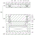
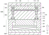
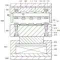
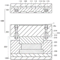
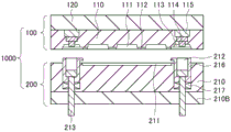
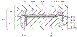
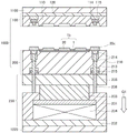
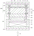
Fig. 1 is a sectional view schematically showing the structure of a resin molding apparatus of the present embodiment. As shown in the drawing, the resin molding apparatus mainly includes a molding die 1000 and a mold closing portion 220. The mold 1000 includes an upper mold (one mold) 100 and a lower mold (the other mold) 200. The upper mold 100 and the lower mold 200 are opposite to each other.
The upper mold 100 includes an upper mold cavity block 110 and an upper mold base block 120. The upper mold cavity block 110 has an upper mold base block 120 fixed to a surface of the mold opposite to a mold surface (a surface opposite to the lower mold 200). A cavity 111, a runner 112 (resin flow path), and a cull portion (residual resin container) 113 are provided on a mold surface (surface on the side opposite to the lower mold 200) of the upper cavity block 110. The cavity 111 is plural. The cavities 111 adjacent to each other communicate with each other through a flow passage 112. The cull portions 113 are provided at both ends of the upper cavity block 110, respectively, by 1. Each cull portion 113 communicates with the adjacent cavity 111 through a runner 112. Then, as described later, the cull portion 113 can accommodate at least a part of the excess resin that was not accommodated in the cavity 111 at the time of mold closing. The upper die 100 further includes an adjusting member (plate height adjusting member) 114, and an adjusting member elastic member 115 that elastically supports the adjusting member 114. The adjustment member 114 is partially disposed inside the residue portion 113 and is fixed to the upper die base 120 by an adjustment member elastic member 115. The adjustment member 114 can move in the opening/closing direction of the mold 1000 by the expansion/contraction of the adjustment member elastic member 115. Then, the capacity of the cull portion 113 is adjusted by the movement of the adjusting member 114, whereby the resin pressure in the cavity 111 can be adjusted.
The resin material (board) contained in the tank 212 generally has a deviation in height (weight). Therefore, the amount of resin supplied to the cavity 111 and the cull portion 113 varies with each molding. Therefore, in order to adjust the volume and injection pressure (resin pressure) of the portions (the cavity 111 and the cull portion 113) into which the resin material is injected at the time of resin molding, the adjusting member (the plate height adjusting member) 114 is movable as described above. The cull portion 113 may be configured to communicate with the cull portion (the left and right cull portions 113 are directly connected to each other). In this way, the communicating of the cull portions 113 can suppress the occurrence of a variation in the injection pressure (injection speed) of the resin material locally due to a difference in the height of the resin material (plate).
The lower die 200 is primarily assembled from a lower cavity block 210. The lower cavity block 210 includes a substrate mounting portion 211. The substrate mounting portion 211 is provided at a position facing the cavity 111 of the upper mold 100 on the mold surface (surface on the side facing the upper mold 100) of the lower mold cavity block 210. The lower die 200 further includes a pot (resin material housing portion) 212 and a plunger 213. The can 212 is disposed on the mold surface of the lower mold cavity block 210 at a position opposite to the cull 113 of the upper mold 100. The plunger 213 penetrates from the inside of the can 212 to the opposite side of the mold surface of the lower cavity block 210. Plunger 213 is movable in the opening/closing direction of mold 1000 (upper mold 100 and lower mold 200) with respect to can 212.
In fig. 1, the plunger 213 further includes a ring (annular member) 214 and a flange 215. A ring 214 is provided on the outer periphery of the plunger 213 at a portion (2 in the figure) of the location where it contacts the lower mold cavity block 210. More specifically, a groove is provided at 2 of the outer periphery of the plunger 213, and a ring 214 is mounted on the groove to hold the plunger 213 vertically with 2 fulcrums of the ring 214. A flange portion 215 is provided at the lower end portion of the plunger 213.
As shown in fig. 1, the wear of the plunger 213 itself can be suppressed by supporting the plunger 213 with the ring 214, and the wear can be dealt with by replacing the ring 214. The ring 214 is not particularly limited, and for example, a fluororesin such as polytetrafluoroethylene, engineering plastic, or the like can be used. The material of the plunger 213 is not particularly limited, and for example, a wear-resistant super steel alloy may be used as the material of the plunger 213. However, since the wear can be suppressed by being supported by the ring 214, steel can be used as a material of the plunger 213 instead of the super steel alloy. When the superalloy constituting the plunger 213 contains cobalt, the cleaning sheet may chemically react with cobalt to cause corrosion of the plunger 213. However, if cobalt-free steel is used as the constituent material of the plunger 213, corrosion of the plunger 213 by such a cleaning sheet can be suppressed or prevented. Further, if steel is used instead of the super steel alloy, the cost of the plunger 213 itself can be reduced.
The mold closing unit 220 includes a holder a block 221, a holder B block 222, a lower mold placing block (mold mounting member) 223, and an elastic member 224. The holder block is composed of the holder a block 221 and the holder B block 222. The elastic member 224 is disposed on the opposite side of the lower mold stage block 223 from the surface facing the upper mold 100. The lower die placement block 223 is elastically supported on the upper surface of the holder B block 222 via an elastic member 224. The lower portion of the lower mold stage block 223 constitutes a flange portion whose peripheral edge portion protrudes. The holder a block 221 is fixed to a peripheral edge portion of an upper surface of the holder B block 222. The outer side surface of the flange portion and the upper surface peripheral portion of the lower mold mounting block 223 and the outer side surface of the elastic member 224 are surrounded by the holder a block 221. In this way, the lower mold placement block 223 and the elastic member 224 are held by the holder blocks (the holder a block 221 and the holder B block 222). The lower mold placing block 223 has a portion other than the flange portion protruding from the upper surface of the holder a block 221. The lower die 200 is attached with a lower die mounting block (die attaching member) 223 as a part of the die closing portion 220 on the opposite side to the surface facing the upper die 100. Then, as will be described later, the mold closing portion 220 is moved in the mold closing direction of the mold 1000 (the upper mold 100 and the lower mold 200), so that the mold 1000 is closed, the plunger 213 is pushed in the direction of the upper mold 100, and the resin material contained in the resin material containing portion 212 is extruded onto the mold surface of the mold 1000 by the plunger 213. As described later, when the mold is closed, since the plunger 213 is pushed in using the holder a block 221, the holder a block 221 corresponds to a "plunger pushing-in member".
The resin molding apparatus of fig. 1 further includes a fixed platen (1 st platen) 1100 and a movable platen (2 nd platen) 1200. The upper mold 100 is attached to the lower surface of the fixed platen 1100, and the mold closing unit 220 is attached to the upper surface of the movable platen 1200 on the lower surface of the holder B block 222.
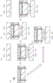
The method of manufacturing a resin molded article using the resin molding apparatus of fig. 1 can be performed, for example, as shown in fig. 2 to 14. Hereinafter, it will be specifically explained.
First, as shown in fig. 2, the substrate 1 is supplied (placed) to the substrate placing portion 211 of the lower die 200, and the plate (resin material) 20a is supplied to the pot 212. At this time, the lower mold 200 and the upper mold 100 are heated by a heater (not shown). The plate 20a is not particularly limited, and may be a thermoplastic resin or a thermosetting resin, but for example, a thermosetting resin such as an epoxy resin or a silicone resin can be used.
Then, as shown in FIGS. 3 to 6, mold closing and resin molding are performed.
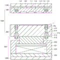
First, as shown in fig. 3, the movable platen 1200 is raised in the direction of arrow X1. Thereby, the mold closing portion 220, the lower mold 200, and the movable platen 1200 are lifted together, and the mold surface of the lower mold 200 and the mold surface of the upper mold 100 are brought into contact as shown in the drawing. At this time, the plate 20a is melted by the heat of the lower mold 200, and becomes a molten resin (flowable resin) 20b as shown in the drawing.
Subsequently, as shown in fig. 4, the movable platen 1200 is further raised in the direction of arrow X2. Thereby, the mold closing portion 220 and the lower mold 200 are raised together with the movable platen 1200, and the plunger 213 is brought into contact with the holder a block (holder block) 221 as shown in the drawing.
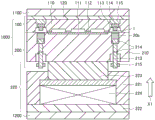
Subsequently, as shown in fig. 5, the movable platen 1200 is further raised in the direction of arrow X3. At this time, as shown in the drawing, the elastic member 224 contracts, so that the lower mold placing block 223 and the lower mold 200 are maintained at their original positions, and the holder blocks (the holder a block 221 and the holder B block 222) are raised. Thus, as shown in the drawing, plunger 213 is pushed (pushed) into tank 212 by using holder a block (holder block) 221, and molten resin 20b is filled into cull portion 113, runner 112, and cavity 111.
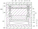
Thereafter, as shown in fig. 6, the heat of the upper mold 100 and the lower mold 200 is used to cure the remaining portion 113, the runner 112, and the flowable resin 20b in the cavity 111 into a cured resin. In fig. 6, a cured resin (hereinafter, simply referred to as "cured resin") in the runner 112 and the cavity 111 is denoted by a reference numeral 20, and a cured resin (hereinafter, referred to as "excess resin" or "unnecessary resin") in the cull portion 113 is denoted by a reference numeral 20 d. Thus, one surface of the substrate 1 is resin-molded with the cured resin 20 to form a resin molded product (packaged substrate) 1 b. Then, after the fluid resin 20b is cured to become the cured resin 20 and the excess resin (unnecessary resin portion) 20d, the movable platen 1200 is lowered in the direction of arrow Y1 as shown in fig. 6. At this point, as shown, the upward force applied to the elastic member 224 is released and the elastic member 224 is again stretched. Thereby, the lower mold placing block 223 and the lower mold 200 are maintained at the original positions, and the holder blocks (the holder a block 221 and the holder B block 222) are lowered.
Next, as shown in fig. 7 to 14, the resin molded product 1b is released from the mold (removed from the mold), and unloaded (conveyed to the outside of the mold).
First, as shown in fig. 7, the movable platen 1200 is further lowered in the direction of arrow Y2. Thus, as shown in the drawing, the mold closing portion 220 and the lower mold 200 are lowered together with the movable platen, and the upper mold 100 and the lower mold 200 are opened. Thereby, as shown in the drawing, the resin molded article 1b (the substrate 1 and the cured resin 20) and the excess resin 20d are lowered together with the lower mold 200 and released from the upper mold 100. For example, the surplus resin 20d of the adjustment member 114 can be pressed by the restoring force (elongation force) of the adjustment member elastic member 115, and the resin molded article 1b and the surplus resin 20d can be released from the upper mold 100.
Thereafter, as shown in fig. 8, movable platen 1200 is further lowered in the direction of arrow Y3, thereby further lowering lower die 200. In this state, as shown in fig. 9 and 10, the unloader 300 is moved in the direction of arrow a1 (the direction from the outside of the mold 1000 toward the space between the upper mold 100 and the lower mold 200), and the unloader 300 is moved into the space between the upper mold 100 and the lower mold 200. As shown in the drawing, the unloader 300 includes a suction pad 301 for sucking the cured resin 20 and the excess resin 20 d.
Next, as shown in fig. 11, the suction pad 301 is lowered in the direction of arrow B1, and the cured resin 20 of the resin molded product (packaged substrate) 1B and the excess resin (unnecessary resin portion) 20d connected to the cured resin 20 are sucked.
Further, as shown in fig. 12, the suction pad 301 is raised in the direction of arrow C1 while the resin molded article 1b and the excess resin 20d are being sucked. Thereby, as shown in the drawing, the resin molded product 1b and the excess resin 20d are released from the mold surface of the lower mold 200. At this time, when the surplus resin 20d and the plunger 213 are not separated, the plunger 213 and the surplus resin 20d ascend together. However, as shown in the drawing, the flange portion 215 of the plunger 213 is caught on the lower cavity block 210, and the plunger 213 cannot be raised to a predetermined height or more. Then, as shown in fig. 13, if the residual resin 20d is further raised in the direction of the arrow C2 together with the suction pad 301, the residual resin 20d and the plunger 213 are separated.
Then, as shown in fig. 14, the unloader 300 is moved in the direction of an arrow D1 (toward the outside of the mold 1000) together with the resin molded article 1b and the excess resin 20D, and is withdrawn from the mold 1000. Thereafter, the resin molded article 1b and the excess resin 20d are separated from the unloader 300, and the excess resin 20d is separated from the resin molded article 1b (not shown). This enables the resin molded article 1b to be produced.
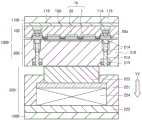
Fig. 1 to 14 show examples of the resin molding apparatus and the resin molding method using the same of the present invention. However, the resin molding apparatus and the resin molding method according to the present invention are not limited to the examples of fig. 1 to 14, and various modifications are possible. For example, as in the resin molding apparatus shown in fig. 15A to C, a hydraulic mechanism 228 may be provided instead of the elastic member 224. The resin molding apparatus of fig. 15A to C is the same as the resin molding apparatus of fig. 1 to 14 except that the mold closing section 220 includes a hydraulic mechanism 228 instead of the elastic member 224. The method of manufacturing a resin molded article using the resin molding apparatus can be performed in the same manner as in fig. 2 to 14, for example. Fig. 15A is a diagram showing a state where substrate 1 and plate (resin material) 20a are supplied to lower die 200, and corresponds to the step of fig. 2. Fig. 15B is a diagram showing a state in which the plate 20a is melted into a molten resin (flowable resin) 20B, and the movable platen 1200, the mold closing portion 220, and the lower mold 200 are lifted up to bring the lower mold 200 into contact with the upper mold 100. Fig. 15B corresponds to the step of fig. 3. Fig. 15C is a view showing a state in which molten resin (flowable resin) is injected into cavity 111, runner 112, and cull portion 113 using plunger 213, and corresponds to the step of fig. 5.
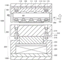
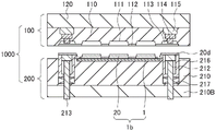
In addition, for example, in the mold 1000 of the resin molding apparatus shown in fig. 1 to 14, the lower mold 200 may have a structure shown in fig. 16(a) to (c), for example. Fig. 16(a) shows the structure of the lower mold 200 together with the mold closing portion 220 and the movable platen 1200. The lower die 200 of fig. 16(a) is the same as the lower die 200 of fig. 1 to 14 except that the lower cavity block 210 includes a through hole (residual resin drain hole) 218. As shown, the through hole 218 communicates with the tank 212 and extends from the tank 212 to the side opposite to the surface of the lower cavity block 210 facing the upper mold 100. With this configuration, the residual resin in the tank 212 can be discharged by dropping the resin from the through hole 218 after the resin molding.
Fig. 16(b) is a partially enlarged view of the plunger 213 and the through hole (residual resin drain hole) 218 in fig. 16 (a). As shown in the drawing, the through hole 218 is provided in plural number so as to surround the plunger 213. By providing the through hole 218 only around the portion of the plunger 213, the upper end portion (flange-shaped portion) of the plunger 213 is caught by the portion where the through hole 218 is not provided, and the plunger 213 cannot fall off.
Fig. 16(c) is a schematic diagram showing a modification of the plunger 213. The figure shows only the lower part of the plunger 213 enlarged. Fig. 1 to 14 show an example in which the lower end of the plunger 213 (the portion in contact with the holder a block 221) is flat, as shown in the left side of fig. 16 c. However, as shown in the right side of fig. 16(c), the area of the contact portion of the plunger 213 with the cage a block 221 may be reduced as much as possible (for example, only at approximately 1 point of the tip of the convex portion 213 a) by the convex portion 213a having a circular lower end. In this way, for example, the dependence on the flatness (flatness) of the upper surface of the retainer a block 221 and the lower surface of the plunger 213 can be reduced, and the plunger 213 can be raised straight in the gravity direction.
According to the resin molding apparatus of the present invention, for example, the structure of the resin molding apparatus for transfer molding can be simplified. Specifically, for example, as shown in the embodiment, resin injection is performed by moving a plunger up and down by a clamping force of a press (mold closing portion). In this way, since the mold closing mechanism also serves as a transmission drive mechanism (a mechanism for injecting the resin material into the mold surface of the mold), resin molding can be performed without providing a transmission drive mechanism other than the mold closing mechanism, and therefore, the structure of the resin molding apparatus can be simplified.
[ example 2 ]
Next, another embodiment of the present invention will be explained.
In this embodiment, an example in which the resin molding apparatus includes a temperature raising stage, a resin molding stage, a curing stage, and a discharging stage will be described.
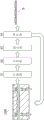
Fig. 17 is a schematic view showing a schematic view of a resin molding apparatus according to the present embodiment and a method for manufacturing a resin molded product using the same. As shown in the drawing, the resin molding apparatus includes a temperature raising stage S1, a resin molding stage S2, a curing stage S3, and a discharging stage S4. The molding die 1000 can be attached to and detached from the segments S1 to S4 and can be moved between the segments S1 to S4. The temperature rise section S1 raises the temperature of the molding die 1000. The resin molding stage S2 includes a mold 1000 and a mold closing portion, and performs resin molding. The curing section S3 cures the resin in the molding die 1000. The ejection section S4 releases the resin molded article 1b from the molding die 1000. The mold 1000 is not particularly limited, but may be the same as the mold 1000 of the resin molding apparatus of example 1 (fig. 1 to 16), for example. The mold closing section is not particularly limited, and may be the same as the mold closing section 220 of the resin molding apparatus according to example 1 (fig. 1 to 16), for example.
In the case of performing the method of manufacturing the resin molded product, for example, as shown in fig. 17, the molding die 1000 may be circulated between the stages S1 to S4. Specifically, for example, as shown in the drawing, the mold 1000 is moved in the order of the temperature rise stage S1, the resin molding stage S2, the curing stage S3, and the discharge stage S4 to produce the resin molded product 1 b. After the resin molded product 1b is collected in the ejection stage S4, the mold 1000 is returned to the temperature raising stage S1, and the method of manufacturing the resin molded product is performed again. The mechanism and method of moving (conveying) the mold 1000 are not particularly limited. The mold 1000 can be transported by a known technique such as a robot or a turntable.
In the above-described embodiment 1, 1 stage of the resin molding apparatus has all the functions of the temperature raising stage, the resin molding stage, the curing stage, and the discharging stage. That is, in example 1, as shown in fig. 2 to 14, the resin molding stage including the mold 1000 and the mold closing portion has a function of a temperature raising stage for raising the temperature of the mold 1000, a function of a curing stage for curing the resin in the mold 1000, and a function of a discharging stage for releasing the resin molded product 1b from the mold 1000.
In contrast, in the present embodiment, the resin molding apparatus is provided with a stage different from the resin molding stage, and a function different from the resin molding stage is provided, whereby the following effects can be obtained, for example. For example, by performing the release of the resin molded product from the molding die in the ejection stage different from the molding stage, it is possible to eliminate the need to provide an ejection mechanism (e.g., a pin, an ejection lever, etc.) in the molding die. That is, the structure of the molding die can be simplified. Also, for example, by heating the molding die and curing the resin in a curing section different from the molding section, during which additional resin molding can be performed in the molding section. In this way, since it is not necessary to wait for the time until the resin is cured in the molding stage, the operating efficiency of the molding stage is improved, and therefore, it is possible to expect a reduction in the molding cycle time.
In the curing step, for example, the mold may be heated to a high temperature, and the resin in the mold may be cured at the temperature. In this case, the curing section makes the function of raising the temperature of the molding die the same as that of the heating section. Therefore, in this case, the temperature raising section may double as the curing section.
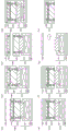
Specifically, the method of manufacturing a resin molded article using the resin molding apparatus shown in the schematic view of fig. 17 can be performed as shown in fig. 18 to 20, for example.
First, as shown in the process sectional views of fig. 18(a) to (d), the mold is heated in a temperature raising stage. As shown, the temperature raising stage includes a fixed platen 1110 and a movable platen 1210. The fixed platen 1110 includes a heater 1111, and the movable platen 1210 includes a heater 1211. The heaters 1111 and 1211 are not particularly limited, but may be, for example, a cartridge heater or the like. The movable platen 1210 is disposed below the fixed platen 1110, and the mold 1000 can be sandwiched between the fixed platen 1110 and the movable platen 1210.
First, as shown in fig. 18(a), a mold 1000 is prepared. The molding die 1000 may be the same as the molding die 1000 of embodiment 1 (fig. 1 to 14). In fig. 19 and 20 described later, the same mold 1000 can be used. On the other hand, the fixed platen 1110 and the movable platen 1210 are heated by the heaters 1111 and 1211 in advance. Next, as shown in fig. 18(b), the mold 1000 is carried to a temperature raising stage where the temperature is raised in advance, and is placed and fixed on the movable platen 1210. The method of fixing the mold 1000 to the movable platen 1210 is not particularly limited, and for example, an electrostatic chuck, a mechanical chuck, or the like can be used. Next, as shown in fig. 18(c), the movable platen 1210 is raised, and the mold 1000 is clamped (sandwiched) between the fixed platen 1110 and the movable platen 1210, and the temperature of the mold 1000 is raised. After the temperature rise of the mold is completed, the movable platen 1210 is lowered as shown in fig. 18 (d). Thereafter, the mold 1000 is taken out from the temperature raising stage and conveyed to the molding stage.
First, for example, instead of the structures of fig. 18(a) to (d), the temperature raising stage may have a structure as shown in fig. 18 (e). The temperature raising stage in fig. 18(e) is the same as the temperature raising stages in fig. 18(a) to (d), except that the fixed platen 1110 and the heater 1111 are not provided, and the temperature raising stage 1212 instead of the movable platen 1210 is provided. The temperature raising stage 1212 and the movable platen 1210 are also provided with a heater 1211. In this case, instead of the steps of fig. 18(b) to (d), as shown in fig. 18(e), the mold 1000 is placed and fixed on a temperature raising stage 1212 in which the temperature is raised in advance by using a heater 1211. After the mold 1000 is heated, it is taken out from the heating stage and conveyed to the molding stage.
Next, as shown in the step cross-sectional views of fig. 19(a) to (h), resin molding is performed in a resin molding stage. In FIGS. 19(a) to (h), the same members as those in example 1 (FIGS. 1 to 14) are denoted by the same reference numerals. As shown in fig. 19(a) to (h), the resin molding stage includes a mold closing section 220, a fixed platen (1 st platen) 1100, and a movable platen (2 nd platen) 1200. The mold closing section 220, the fixed platen 1100 and the movable platen 1200 may be the same as those of embodiment 1 (fig. 1 to 14). Further, for example, a heater (for example, cartridge heater) may be provided in the mold closing section 220, the fixed platen 1100, the movable platen 1200, and the like in the same manner as in the temperature raising stage, and the mold 1000 may be heated.
First, as shown in fig. 19(a), the mold 1000 is carried from the temperature raising stage to the resin molding stage and placed on the mold closing section 220.
Next, as shown in fig. 19(b), the movable platen 1200 is raised and the upper mold 100 is brought into contact with the fixed platen 1100. In this state, the upper die 100 is fixed to the fixed platen 1100, and the lower die 200 is fixed to the die closing portion 220. In this case, a method of fixing the upper mold 100 and the lower mold 200 is not particularly limited, and for example, an electrostatic chuck, a mechanical chuck, or the like may be used.
Next, as shown in fig. 19(c), the substrate and the board (resin material) are supplied to the lower mold 200. This procedure may be the same as in fig. 2, for example.
Next, the plate (resin material) is melted into a molten resin (flowable resin). Thereafter, as shown in fig. 19 d, the plunger of the lower mold 200 is pushed (raised) while the mold is closed by raising the mold closing portion 220, and the molten resin (flowable resin) is supplied to the mold surface of the mold 1000. This step can be the same as in FIGS. 3 to 5, for example.
Next, as shown in fig. 19(e) to (h), the mold is opened and the mold 1000 is taken out. In these steps, unlike fig. 6 to 14 of example 1, the solidification of the molten resin (flowable resin), the release of the resin molded article, and the conveyance of the resin molded article to the outside of the mold were not performed. This is because the solidification of the molten resin (flowable resin) is performed in a solidification stage described later, and the release of the resin molded product and the conveyance of the resin molded product to the outside of the mold are performed in a discharge stage described later.
First, as shown in fig. 19(e), the movable platen 1200 is lowered together with the mold closing section 220 and the mold 1000. Thereby, as shown, the upper mold 100 is separated from the fixed platen 1100.
Next, as shown in fig. 19(f), the movable platen 1200 is further lowered together with the mold closing section 220 and the mold 1000.
Thereafter, as shown in fig. 19(g) to (h), the mold 1000 is moved to the outside of the molding stage and conveyed into a curing stage (not shown).
Thereafter, the mold 1000 is heated in a curing stage (not shown) to raise the temperature, and the fluid resin in the mold 1000 is cured. Thus, a resin molded article is produced. The solidification stage may have the same structure as the temperature raising stage shown in fig. 18(a) to (e), for example. Further, for example, the temperature raising stage shown in FIGS. 18(a) to (e) may double as the curing stage. The step of curing the flowable resin in the mold 1000 through the curing stage is not particularly limited, and for example, the same steps as those in fig. 18(a) to (e) may be performed except that the mold 1000 is filled with the flowable resin.
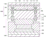
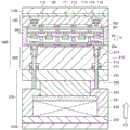
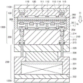
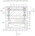
Then, as shown in the step cross-sectional views of fig. 20(a) to (f), the resin molded product is released from the mold 1000 in the ejection stage. As shown, the discharge stage includes a holder 230, movable platens 1120 and 1220. Both movable platens 1120 and 1220 can move up and down. The movable platen 1120 can fix the upper die 100 on its lower surface. The movable platen 1220 can mount and fix the holder 230 on the upper surface thereof. The holder 230 includes holder a blocks 231, holder B blocks 232, discharge plate mounting blocks 233, elastic members 234, discharge plates 235, and discharge rods 236. The holder a block 231, the holder B block 232, the eject plate mounting block 233, and the elastic member 234 have the same configurations as the holder a block 221, the holder B block 222, the lower mold mounting block (mold mounting member) 223, and the elastic member 224 of the mold closing unit 220 of embodiment 1 (fig. 1 to 14), respectively. The exhaust plate 235 is fixed to the upper surface of the exhaust plate mount block 233. The discharge plate 235 includes a discharge rod 236, and an upper surface of the discharge plate 235 can contact the entire lower surface of the lower mold 200. The discharge rod 236 is disposed at a position corresponding to the plunger of the lower die 200 and is vertically movable in the discharge plate 235. As will be described later, by raising the holder a block 231, a part of the discharge rod 236 can be pushed out from the upper surface of the discharge plate 235. In this way, a part of the plunger of the lower mold 200 can be pushed out from the upper surface of the lower mold 200 by the discharge rod 236, and the cured excess resin can be separated from the resin molded product.
The step of releasing the resin molded article shown in fig. 20(a) to (f) can be performed as follows.
First, as shown in fig. 20(a), a molding die 1000 is placed and fixed on the discharge plate 235. The fixing method is not particularly limited, and for example, an electrostatic chuck, a mechanical chuck, or the like can be used. At this time, for example, the mold 1000 may be subjected to vibration, heat (linear expansion due to temperature rise), or the like to assist mold release.
Next, as shown in fig. 20(b), movable platen 1220 is raised together with holder 230 and mold 1000, and upper mold 100 is fixed to the lower surface of movable platen 1120. The fixing method is not particularly limited, and for example, an electrostatic chuck, a mechanical chuck, or the like can be used.
Next, as shown in fig. 20(c), movable platen 1120 is raised together with upper mold 100, and movable platen 1220 is lowered together with holder 230 and lower mold 200. This allows the upper mold 100 and the lower mold 200 to be opened. In this state, as shown in the drawing, the unloader 300 is brought between the upper mold 100 and the lower mold 200. As shown in the drawing, the unloader 300 includes a suction pad 301 for sucking the cured resin 20 and the excess resin 20d, as in the unloader 300 of fig. 9 to 14 of embodiment 1. Further, as shown in the drawing, the unloader 300 shown in fig. 20 includes a packaged substrate holding member (resin molded article holding member) 302.
Next, as shown in fig. 20(d), movable platen 1120 is lowered together with upper mold 100, and movable platen 1220 is raised together with holder 230 and lower mold 200. Thus, as shown, the unloader is clamped and fixed using the upper mold 100 and the lower mold 200. Further, as shown in the drawing, the resin molded article holding member 302 is lowered in the direction of arrow I1 to hold the resin molded article (packaged substrate) 1 b. As shown in the figure, the resin-molded article holding member 302 holds the resin molded article 1b by pressing the portion of the cured resin 20 cured in the runner 112 from above. In addition, for example, instead of the part of the cured resin 20 that is cured in the runner 112, the part that is cured in the cavity 111 may be pressed from above using the resin molded article holding member 302. Further, movable platen 1220 can be raised together with holder 230 and lower die 200. At this time, as shown in the drawing, a part of the discharge rod 236 is pushed out from the upper surface of the discharge plate 235 by the rising of the holder a block 231. Thereby, a part of the plunger of the lower mold 200 is pushed out from the upper surface of the lower mold 200 by the discharge rod 236, and the remaining resin after the curing is separated from the resin molded product as shown in the drawing.
Thereafter, as shown in fig. 20(e), the resin molded product (packaged substrate) and the excess resin separated from the resin molded product are adsorbed by the suction pad 301 of the unloader 300. The unloader 300 is then carried out of the discharge section (not shown) together with the resin molded product and the excess resin. These steps can be performed, for example, in accordance with FIGS. 11 to 14 of embodiment 1.
Further, as shown in fig. 20(f), the molding die 1000 is separated from the movable platen 1120. Thereafter, the molding die 1000 is separated from the holder 230 and conveyed out of the ejection section. The mold 1000 can be transported to the temperature rise stage of fig. 18 again, for example, and the method for manufacturing the resin molded product described in fig. 18 to 20 can be performed again.
In the present invention, the structure of the mold of the resin molding apparatus is not limited to the mold 1000 shown in fig. 1 to 20. Fig. 21 to 28 show several modifications of the mold.
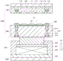
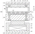
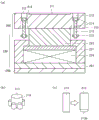
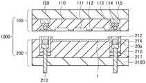
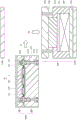
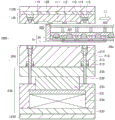
Fig. 21 is a sectional view schematically showing a modification of the molding die. As shown in the drawing, the mold 1000 is the same as the mold 1000 shown in fig. 1 to 20 except that the lower mold 200 includes the excess resin separating member (excess resin separating block) 216, the elastic member 217 for the excess resin separating member, and the lower mold base 210B, and does not include the ring 214. In this figure, lower mold cavity block 210 is secured to the upper surface of lower mold base block 210B. Plunger 213 penetrates lower die base block 210B. Excess resin separating member 216 is disposed so as to surround the outer periphery and the lower surface of tank 212, and is elastically supported by lower die block 210B via an elastic member 217 for excess resin separating member. The excess resin separating member 216 is movable up and down by the expansion and contraction of the excess resin separating member elastic member 217. The plunger 213 penetrates the excess resin separating member 216 and the excess resin separating member elastic member 217. The excess resin separating member 216 is disposed directly below the residue part (excess resin accommodating part) 113, and excess resin in the residue part 113 can be pressed by the excess resin separating member 216. As shown in the figure, a protruding portion protruding in the horizontal direction is formed at the substrate-side end portion of the upper portion of the excess resin separating member 216. Thereby, when the upper mold 100 and the lower mold 200 are closed, the end portion of the substrate on the cull portion (excess resin container) 113 side is sandwiched by the mold surface of the lower mold 200 and the end portion of the excess resin separating member 216.
The method of manufacturing a resin molded product using the mold 1000 of fig. 21 can be performed, for example, in the same manner as in fig. 1 to 14. In the case of the mold 1000 of fig. 21, the cured resin of the resin molded product and the excess resin in the residue portion 113 can be separated by opening the mold after the curing of the resin. An outline of a method for manufacturing a resin molded product using the mold 1000 of fig. 21 can be shown in a process sectional view of fig. 22 to 24, for example. First, as shown in fig. 22, the substrate 1 is supplied (placed) to the substrate placing portion 211 of the lower die 200, and the plate (resin material) 20a is supplied to the pot 212. Then, the mold is heated and closed in the same manner as in fig. 2 to 5. Thereby, as shown in fig. 23, the plunger 213 is pushed into the can 212 in a state where the mold surface of the lower mold 200 and the mold surface of the upper mold 100 are in contact (mold closed). As shown in fig. 23, the molten resin 20b obtained by melting the resin material 20a is filled into the cull portion 113, the runner 112, and the cavity 111. Thereafter, similarly to fig. 6 to 8, the resin in the cavity 111 and the remaining resin in the cull portion 113 are cured, and then the mold is opened to release the mold. When the mold is opened and the mold is released, as shown in fig. 24, the excess resin separating member 216 is lifted relative to the lower mold 200 by the extension of the excess resin separating member elastic member 217 in a state where the resin molded article 1b is fixed to the lower mold 200. Thereby, since the excess resin 20d solidified in the cull portion 113 is pushed up by the excess resin separation member 216, the resin 20 solidified in the cavity 111 and the excess resin 20d solidified in the cull portion 113 can be separated as shown in the drawing.
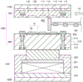
Fig. 25 is a sectional view schematically showing another embodiment of the molding die. As shown in the drawing, the upper die 100 does not have the cull portion 113 in the molding die 1000. A cull portion 113B communicating with the runner 112 of the upper mold 100 is formed at an upper portion of the can 212 of the lower mold 200. Further, the lower surface of the substrate mounting portion 211 of the lower die 200 is recessed at a position corresponding to the upper die cavity 111, and a lower die cavity 111B is formed. The mold 1000 of fig. 25 is the same as the mold 1000 shown in fig. 1 to 20 except that these and other mold parts do not have the ring 214.
The method of manufacturing a resin molded product using the mold 1000 of fig. 25 can be performed, for example, in the same manner as in fig. 1 to 14. The mold 1000 of fig. 25 can inject the flowable resin injected into the upper mold cavity 111 into the lower mold cavity 111B from the hole of the substrate by using a perforated substrate, for example.
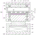
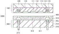
Fig. 26 is a cross-sectional view schematically showing still another modification of the molding die. As shown in the drawing, the intermediate die 400 is disposed between the upper die 100 and the lower die 200 in the molding die 1000. The intermediate mold 400 includes an intermediate mold resin material accommodating portion 413 at a position directly above the tank (resin material accommodating portion) 212. The intermediate mold resin material accommodating portion 413 can accommodate the resin material (plate) 20a, communicate with the residue portion 113 at the time of mold closing, and can inject the molten (fluidized) resin material (flowable resin) into the residue portion 113. That is, the intermediate mold resin material accommodating portion 413 doubles as an intermediate mold resin passage. The lower die 200 in fig. 26 does not include the substrate mounting portion 211. Instead, in fig. 26, the intermediate mold 400 includes a substrate mounting portion 411 on a surface on a side opposite to the upper mold 100. The lower surface of the substrate mounting portion 411 of the intermediate mold 400 is recessed at a position corresponding to the upper mold cavity 111, and an intermediate mold cavity 412 is formed. The mold 1000 of fig. 26 is the same as the mold 1000 of fig. 1 to 20 except that the ring 214 is not provided.
Fig. 27 is a plan view of the upper cavity block 110 and the intermediate mold 400 of fig. 26, respectively, as viewed from the mold surface side. As described above, the intermediate mold resin material accommodating portion (intermediate mold resin passage) 413 corresponds to the position of the cull portion 113 of the upper mold cavity block 110, and the intermediate mold cavity 412 corresponds to the position of the cavity 111 of the upper mold cavity block 110.
The method of manufacturing the resin molding apparatus using the mold 1000 of fig. 26 can be performed, for example, in the same manner as in fig. 1 to 14. Fig. 28(a) to (b) are schematic process cross-sectional views. Fig. 28(a) shows a state where the plate 20a is accommodated in the tank 212. After the substrate is further placed on the substrate placing portion 411 of the intermediate mold from this state, the plate 20a is melted (fluidized) and then the mold is closed in the same manner as in fig. 3 to 5, and the molten material is injected into the cull portion 113, the runner 112, and the cavity 111. In the case of the mold 1000 shown in fig. 26, the flowable resin injected into the upper mold cavity 111 can be injected into the intermediate mold cavity 412 from the hole of the substrate by using a perforated substrate, for example. Thereafter, if the fluid resin is cured, the fluid resin becomes the cured resin 20 and the excess resin (unnecessary resin portion) 20d as shown in fig. 28 (b). Other steps can be performed in the same manner as in fig. 1 to 14, as described above.
The mold 1000 of fig. 21 to 28 can be further arbitrarily deformed. For example, although the ring 214 is omitted in fig. 21 to 28, the ring 214 may be provided in the same manner as in fig. 1 to 20. For example, as shown in fig. 16(a) to (c), the lower die may include a through hole (residual resin drain hole) 218, and the lower end of the plunger 213 (the portion in contact with the holder a block 221) may have a circular shape. Further, in the present invention, the mold is not limited to the structure of the mold 1000 shown in fig. 1 to 28, and any mold can be used. For example, in the mold 1000 shown in fig. 1 to 28, the substrate 1 is provided (placed) on the substrate placing portion 211 of the lower mold 200, but the present invention is not limited thereto, and the substrate may be provided on the upper mold. For example, in the mold 1000 of fig. 1 to 24, only the upper mold includes the cavity 111, and in the mold of fig. 25 to 28, both the upper mold and the lower mold include the cavity, but the present invention is not limited thereto, and only the lower mold may include the cavity.
Next, another example of the step of releasing the resin molded product from the mold 1000 in the ejection stage will be described with reference to fig. 29 to 43. In FIGS. 29 to 43, the same members as those in FIGS. 20(a) to (f) are denoted by the same reference numerals. In the ejection stage of fig. 29 to 43, a fixed platen 1100 is provided instead of the movable platen 1120.
First, as shown in fig. 29, the mold 1000 holding the resin molded article 1b after resin molding and the excess resin 20d is conveyed to the discharge stage. Specifically, as shown in the drawing, the molding die 1000 is first conveyed (moved) in the direction of arrow E1 (the direction from the outside toward the inside of the ejection section) and positioned between the fixed platen 1100 and the holder 230. Thereafter, the mold 1000 is moved in the direction of arrow E2 (downward), and is placed on and fixed to the discharge plate 235. The fixing method is not particularly limited, and for example, an electrostatic chuck, a mechanical chuck, or the like can be used. At this time, for example, the mold 1000 may be subjected to vibration, heat (linear expansion due to temperature rise), or the like to assist mold release.
Next, as shown in fig. 30, movable platen 1220 is raised in the direction of arrow F1 together with holder 230 and molding die 1000, and upper die 100 is fixed to the lower surface of fixed platen 1100. The fixing method is not particularly limited, and for example, an electrostatic chuck, a mechanical chuck, or the like can be used.
Next, as shown in fig. 31, movable platen 1220 is lowered in the direction of arrow G1 together with holder 230 and lower die 200. Thereby, the upper mold 100 and the lower mold 200 are opened. Thus, as shown in the drawing, the resin molded product 1b (cured resin 20) and the excess resin (unnecessary resin portion) 20d are released from the mold surface of the upper mold 100 while being held on the upper surface of the lower mold 200.
Next, in a state where the upper mold 100 and the lower mold 200 are opened as shown in fig. 31, the unloader 300 is conveyed (moved) in the direction of an arrow H1 (a direction from the outside to the inside of the mold 1000) as shown in fig. 32. Thereby, as shown in fig. 33, the unloader 300 is brought between the upper mold 100 and the lower mold 200. The unloader 300 includes a suction pad 301 for sucking the cured resin 20 and the excess resin 20d, similarly to the unloader 300 of embodiment 1 shown in fig. 9 to 14. Further, as shown in the figure, the unloader 300 shown in fig. 32 and 33 includes a packaged substrate holding member (resin molded product holding member) 302.
Next, as shown in fig. 34, movable platen 1220 is raised in the direction of arrow F2 together with holder 230 and lower die 200. Thus, as shown in the drawing, the unloader is clamped and fixed (clamped) by using the upper mold 100 and the lower mold 200.
Next, as shown in fig. 35, the resin molded article holding member 302 is lowered in the direction of arrow I1 to hold the resin molded article (packaged substrate) 1 b. As shown in the figure, the resin molded article holding member 302 holds the resin molded article 1b by pressing the portion of the cured resin 20 cured in the flow path 112 from above. Further, for example, instead of a portion of the cured resin 20 that is cured in the runner 112, a portion that is cured in the cavity 111 may be pressed from above using the resin molded article holding member 302.
Next, as shown in fig. 36, the movable platen 1220 and the holder blocks (holder a block 231 and holder B block 232) are raised in the direction of arrow F3. At this time, as shown in the drawing, a part of the discharge rod 236 is pushed out from the upper surface of the discharge plate 235 by the rising of the holder a block 231. Thereby, a part of the plunger 213 of the lower mold 200 is pushed out from the upper surface of the lower mold 200 by the discharge rod 236, and the remaining resin 20d that has been cured is separated from the resin molded article 1b as shown in the drawing.
Next, as shown in fig. 37, movable platen 1220 is lowered in the direction of arrow G2 together with holder 230 and lower die 200. Thereby, the clamp of the unloader 300 is released.
Next, as shown in fig. 38, the suction pad 301 of the unloader 300 is lowered in the direction of arrow J1. As a result, as shown in the drawing, the suction pad 301 is brought into contact with and sucked to the portion solidified in the cavity 111 of the solidified resin 20 and the excess resin 20d separated from the resin molded article 1 b.
Next, as shown in fig. 39, the suction pad 301 is raised in the direction of arrow K1. Then, as shown in fig. 40, the suction pad 301 is further raised in the direction of the arrow K2. Thereby, as shown in the drawing, the resin molded product 1b and the excess resin 20d adsorbed on the suction pad 301 are separated from the lower mold 200.
Thereafter, as shown in fig. 41, the unloader 300 is moved (conveyed) in the direction of an arrow L1 (a direction from the inside of the discharge section to the outside) together with the resin molded article 1b and the excess resin 20d, and is withdrawn out of the discharge section.
Then, as shown in fig. 42, movable platen 1220 is raised in the direction of arrow F4 together with holder 230 and lower die 200, and mold 1000 is closed. Then, in this state, the fixing of the fixed platen 1100 and the molding die 1000 is released.
Further, as shown in fig. 43, the movable platen 1220 is lowered in the direction of arrow G3 together with the holder 230 and the mold 1000, and the mold 1000 is separated from the fixed platen 1100. Thereafter, the mold 1000 is separated from the holder 230, moved (conveyed) in the direction of the arrow M1 (the direction from the inside of the ejection section to the outside), and withdrawn out of the ejection section. The mold 1000 can be transported again into the temperature raising stage, for example, and the method of manufacturing the resin molded product can be performed again.
In the present embodiment, the description has been given mainly of an example of a resin molding apparatus including each of a temperature raising stage, a resin molding stage, a curing stage, and a discharging stage. However, the present invention is not limited thereto. For example, the resin molding apparatus of the present invention may include a plurality of at least 1 functional stage among the temperature raising stage, the resin molding stage, the curing stage, and the discharging stage. This can improve the efficiency of manufacturing the resin molded product, for example. For example, a specific 1 segment may have 2 or more functions in each segment. For example, in example 1, as described above, 1 stage of the resin molding apparatus has all 4 functions of the temperature raising stage, the resin molding stage, the curing stage, and the discharging stage. The resin molding apparatus of the present invention is not limited thereto, and for example, a specific 1 stage may have 2 or 3 functions among the 4 stages, and a stage different from the specific 1 stage may have other functions. For example, as described above, the same stage may have both the functions of the temperature raising stage and the curing stage.
The present invention is not limited to the above-described embodiments, and can be arbitrarily and appropriately combined, changed, or selectively used as needed within a range not departing from the gist of the present invention.
The present application claims priority based on the japanese application laid-open at 8/10 of 2017, the disclosure of which is incorporated in its entirety in the present specification.
Description of the reference numerals
1 substrate
1b resin molded article (substrate after encapsulation)
20 curing the resin
20a plate (resin material)
20b molten resin (flowable resin)
20d excess resin (useless resin portion)
100 Upper mould (one mould)
110 upper mould cavity block
111 type cavity
112 flow passage (resin flow path)
113 residual material part (residual resin container)
113B remnant (remnant resin container)
114 adjusting component (plate height adjusting component)
115 elastic member for adjusting member
120 upper die base block
200 lower die (another die)
210 lower die cavity block
211 substrate mounting part
212 tank (resin material container)
213 plunger
213a convex part
214 Ring (Ring component)
215 flange portion
216 residual resin separating member
217 residual resin separating member elastic member
218 through hole (residual resin leak hole)
220 closed mould part
221 holder A block (holder block)
222 holder B block (holder block)
223 lower die carrier block (forming die mounting component)
224 resilient member
228 hydraulic mechanism
230 holder
231 holder A block (holder block)
232 holder B block (holder block)
233 exhaust board carrying block
234 elastic member
235 discharge plate
236 discharge rod
300 unloader
301 suction pad
302 resin molded article holding member (substrate holding member after encapsulation)
400 middle die
411 substrate mounting part
412 intermediate model cavity
413 middle mold resin material holding part (middle mold resin passage)
1000 forming die
1100 fixed pressing board (1 st pressing board)
1110 fixed pressing plate
1111 heater
1120 Movable pressure plate
1200 Movable press plate (No. 2 press plate)
1210 movable press plate
1211 heater
1212 temperature raising table
1220 movable pressure plate
A1 denotes the arrow of the entering direction of the unloader 300
B1 represents an arrow indicating the descending direction of the suction pad 301
C1-C2 show arrows indicating the ascending direction of the suction pad 301
D1 denotes an arrow indicating the exit direction of the unloader 300
E1-E2 show arrows indicating the moving direction of the molding die 1000
F1-F4 show arrows indicating the ascending direction of the movable platen 1220
G1-G3 show arrows indicating the descending direction of the movable platen 1220
H1 denotes an arrow indicating the direction of entry of the unloader 300
I1 represents an arrow in the descending direction of the resin molded article holding member 302
J1 represents an arrow indicating the descending direction of the suction pad 301
K1-K2 show arrows indicating the ascending direction of the suction pad 301
L1 denotes an arrow indicating the exit direction of the unloader 300
M1 denotes an arrow indicating the exit direction of the molding die 1000
X1-X3 arrows indicating the ascending direction of the movable platen 1200
Y1-Y3 show arrows indicating the descending direction of the movable platen 1200
S1 temperature rising section
S2 resin molding segment
S3 curing stage
S4 discharge stage
Claims (13)
1. A resin molding apparatus comprising a molding die and a mold closing part,
the molding die is provided with one die and the other die,
the one mold and the other mold are opposed to each other,
the other mold is mounted on the mold closing part on the opposite side to the one mold-opposing side,
the other mold includes a resin material accommodating portion and a plunger,
the plunger is movable in an opening/closing direction of the molding die with respect to the resin material accommodating portion,
the mold closing part comprises a plunger pushing member, an elastic member and a molding die mounting member,
the other mold is provided with the molding die attaching member on the opposite side to the one mold facing surface,
the elastic member is disposed on the opposite side of the mold mounting member from the other mold opposing surface and elastically supports the mold mounting member,
the plunger pushing member is movable in the opening/closing direction of the molding die relative to the molding die by the expansion/contraction of the elastic member,
by moving the mold closing portion in the mold closing direction of the molding die, the plunger can be pushed in the direction of the one mold by the plunger pushing member while the molding die is closed, and the resin material contained in the resin material containing portion can be extruded to the die surface of the molding die by the plunger.
2. The resin molding apparatus according to claim 1,
the plunger push-in member is a retainer block,
the holder block may hold the molding die mounting member.
3. The resin molding apparatus according to any one of claims 1 to 2,
the single mold includes a cavity, an adjustment member, and an elastic member for the adjustment member that elastically supports the adjustment member,
the adjusting member is movable in the opening/closing direction of the molding die by the expansion/contraction of the elastic member for adjusting member,
by the movement of the adjusting member, the resin pressure in the cavity can be adjusted.
4. The resin molding apparatus according to claim 3,
the one mold is further provided with a surplus resin accommodating portion,
the residual resin containing portion communicates with the cavity and contains at least a part of residual resin that is not contained in the cavity when the mold is closed.
5. The resin molding apparatus according to claim 4,
at least a part of the regulating member is disposed in the remaining resin containing portion,
the capacity of the excess resin container is adjusted by the movement of the adjustment member, and the resin pressure in the cavity can be adjusted.
6. The resin molding apparatus according to any one of claims 1 to 2, further comprising a1 st platen and a 2 nd platen,
said one mold is mounted on said 1 st platen,
the mold closing part is installed on the 2 nd pressing plate.
7. The resin molding apparatus according to any one of claims 1 to 2,
the molding die is further provided with an intermediate die,
the intermediate mold is disposed between the one mold and the other mold,
the intermediate mold includes an intermediate mold resin material accommodating portion and an intermediate mold resin passage.
8. The resin molding apparatus according to any one of claims 1 to 2,
the molding die comprises a cavity, a residual resin accommodating part and a residual resin separating component,
the remaining resin containing portion communicates with the cavity and contains at least a part of remaining resin that is not contained in the cavity when the mold is closed,
after the resin in the cavity and the excess resin are cured, the excess resin separating member is moved up or down relative to one or both of the one mold and the other mold, thereby separating the resin cured in the cavity and the excess resin cured in the excess resin accommodating portion.
9. The resin molding apparatus according to claim 8,
the resin molding device is a device for resin molding a substrate,
when the one mold and the other mold are closed, an end portion of the substrate on the remaining resin containing portion side is sandwiched by a mold surface of the other mold and an end portion of the remaining resin separating member.
10. The resin molding apparatus according to any one of claims 1 to 2,
the other mold is provided with a through hole,
the through hole penetrates from the resin material accommodating portion to the opposite side of the one mold facing surface,
after the resin molding, the residual resin in the resin material accommodating portion can be discharged from the through hole.
11. The resin molding apparatus according to any one of claims 1 to 2,
the resin molding device is provided with a temperature rising section, a resin molding section, a curing section and a discharging section,
the forming die can be assembled and disassembled relative to the sections and can move among the sections,
the temperature raising section raises the temperature of the forming die,
the resin molding section is provided with the mold closing part and performs resin molding,
the curing section cures the resin in the molding die,
the ejection section ejects the resin molded product from the molding die.
12. A method for producing a resin molded article, wherein the resin molding apparatus according to any one of claims 1 to 11 is used, the method comprising,
a resin material accommodating step of accommodating a resin material in a resin material accommodating portion of a mold; and
a mold closing step of closing the molding die,
in the mold closing step, the mold closing portion is moved in a mold closing direction of the mold, and the plunger is pushed in a direction of the one mold while the mold is closed, and the resin material accommodated in the resin material accommodating portion is extruded to a mold surface of the mold by using the plunger.
13. The method for producing a resin molded article according to claim 12,
the resin molding apparatus as set forth in claim 11,
the resin molding method may further include the step of,
a mold-heating step of heating the mold in the heating section; and
a resin curing step of curing the resin in the mold in the curing stage; and
a mold releasing step of releasing the resin molded product from the molding die in the ejection stage,
the resin material accommodating step and the mold closing step are performed in the resin molding section.
Applications Claiming Priority (2)
| Application Number | Priority Date | Filing Date | Title |
|---|---|---|---|
| JP2017155867A JP2019034445A (en) | 2017-08-10 | 2017-08-10 | Resin molding apparatus, and manufacturing method of resin molded product |
| JP2017-155867 | 2017-08-10 |
Publications (2)
| Publication Number | Publication Date |
|---|---|
| CN109383047A CN109383047A (en) | 2019-02-26 |
| CN109383047B true CN109383047B (en) | 2021-02-26 |
Family
ID=65417519
Family Applications (1)
| Application Number | Title | Priority Date | Filing Date |
|---|---|---|---|
| CN201810886070.XA Active CN109383047B (en) | 2017-08-10 | 2018-08-06 | Resin molding device and method for manufacturing resin molded product |
Country Status (4)
| Country | Link |
|---|---|
| JP (1) | JP2019034445A (en) |
| KR (1) | KR102158909B1 (en) |
| CN (1) | CN109383047B (en) |
| TW (1) | TWI689400B (en) |
Families Citing this family (4)
| Publication number | Priority date | Publication date | Assignee | Title |
|---|---|---|---|---|
| JP7417496B2 (en) | 2020-08-28 | 2024-01-18 | Towa株式会社 | Resin molding equipment and method for manufacturing resin molded products |
| JP7341105B2 (en) * | 2020-08-28 | 2023-09-08 | Towa株式会社 | Resin molding equipment and method for manufacturing resin molded products |
| JP7447050B2 (en) * | 2021-04-21 | 2024-03-11 | Towa株式会社 | Molding mold, resin molding equipment, and method for manufacturing resin molded products |
| CN115214164B (en) * | 2022-07-22 | 2023-05-26 | 哈尔滨工程大学 | Bean pod rod preparation device capable of adjusting resin content and preparation method |
Citations (2)
| Publication number | Priority date | Publication date | Assignee | Title |
|---|---|---|---|---|
| JP2004276352A (en) * | 2003-03-14 | 2004-10-07 | Towa Corp | Resin molding machine |
| JP2012166432A (en) * | 2011-02-14 | 2012-09-06 | Apic Yamada Corp | Resin molding method, and resin molding apparatus |
Family Cites Families (10)
| Publication number | Priority date | Publication date | Assignee | Title |
|---|---|---|---|---|
| JPH0584765A (en) | 1991-09-25 | 1993-04-06 | Mitsubishi Materials Corp | Mold clamping device of transfer molding machine |
| CA2098409A1 (en) * | 1992-06-22 | 1993-12-23 | Chun P. Lau | Automatic molding system |
| JP3542177B2 (en) * | 1994-10-07 | 2004-07-14 | 株式会社秩父富士 | Resin mold manufacturing equipment |
| JP2010153497A (en) * | 2008-12-24 | 2010-07-08 | Shinko Electric Ind Co Ltd | Molding method and molding apparatus |
| JP2010165938A (en) * | 2009-01-16 | 2010-07-29 | Sony Corp | Resin sealing apparatus |
| JP6084502B2 (en) * | 2013-03-28 | 2017-02-22 | 日本バルカー工業株式会社 | Mold molded product take-out device and mold molded product manufacturing device |
| JP6137679B2 (en) * | 2013-05-13 | 2017-05-31 | アピックヤマダ株式会社 | Resin molding apparatus and resin molding method |
| JP6339408B2 (en) * | 2014-05-12 | 2018-06-06 | Towa株式会社 | Mold apparatus, compression molding apparatus and compression molding method |
| WO2016125571A1 (en) * | 2015-02-04 | 2016-08-11 | アピックヤマダ株式会社 | Resin molding die, resin molding method, and method for producing resin molded article |
| JP6598642B2 (en) * | 2015-11-09 | 2019-10-30 | Towa株式会社 | Resin sealing device and resin sealing method |
-
2017
- 2017-08-10 JP JP2017155867A patent/JP2019034445A/en active Pending
-
2018
- 2018-07-02 TW TW107122796A patent/TWI689400B/en active
- 2018-08-06 CN CN201810886070.XA patent/CN109383047B/en active Active
- 2018-08-09 KR KR1020180093171A patent/KR102158909B1/en active IP Right Grant
Patent Citations (2)
| Publication number | Priority date | Publication date | Assignee | Title |
|---|---|---|---|---|
| JP2004276352A (en) * | 2003-03-14 | 2004-10-07 | Towa Corp | Resin molding machine |
| JP2012166432A (en) * | 2011-02-14 | 2012-09-06 | Apic Yamada Corp | Resin molding method, and resin molding apparatus |
Also Published As
| Publication number | Publication date |
|---|---|
| TWI689400B (en) | 2020-04-01 |
| TW201910091A (en) | 2019-03-16 |
| CN109383047A (en) | 2019-02-26 |
| KR102158909B1 (en) | 2020-09-22 |
| KR20190017683A (en) | 2019-02-20 |
| JP2019034445A (en) | 2019-03-07 |
Similar Documents
| Publication | Publication Date | Title |
|---|---|---|
| CN109383047B (en) | Resin molding device and method for manufacturing resin molded product | |
| KR101832597B1 (en) | Resin Sealing Apparatus and Resin Sealing Method | |
| CN108688050B (en) | Molding die, resin molding device, resin molding method, and method for manufacturing resin molded article | |
| KR102192241B1 (en) | Transportation device, resin molding device, method for delivering molding target to molding die, and method for preparing resin molding product | |
| CN107424939B (en) | Compression molding device, resin package manufacturing device, compression molding method, and resin package manufacturing method | |
| CN108028236B (en) | Resin sealing device and resin sealing method | |
| CN108028235B (en) | Resin sealing device and resin sealing method | |
| CN109719898B (en) | Resin molding apparatus and method for manufacturing resin molded product | |
| KR20190017684A (en) | Resin molding product transportation device, resin molding device and method for preparing resin molding product | |
| CN113597365B (en) | Method for producing resin molded article | |
| CN108568929B (en) | Resin molding apparatus, resin molding method, and method for manufacturing resin molded article | |
| CN111216301B (en) | Molding die, resin molding device, and method for manufacturing resin molded article | |
| CN109689330B (en) | Compression molding device, compression molding method, and method for manufacturing compression molded product | |
| CN110065191B (en) | Molding die, resin molding apparatus, and method for manufacturing resin molded product | |
| JP2022039811A (en) | Resin molding device and manufacturing method of the resin molding | |
| JP7034702B2 (en) | Resin molding equipment and manufacturing method of resin molded products | |
| KR20190090778A (en) | Compression Molding Apparatus, Compression Molding Method and Manufacturing Method of Compression Molded Article | |
| CN113573867B (en) | Resin molding device and method for manufacturing resin molded product | |
| JP7430125B2 (en) | Molding mold, resin molding equipment, and method for manufacturing resin molded products |
Legal Events
| Date | Code | Title | Description |
|---|---|---|---|
| PB01 | Publication | ||
| PB01 | Publication | ||
| SE01 | Entry into force of request for substantive examination | ||
| SE01 | Entry into force of request for substantive examination | ||
| GR01 | Patent grant | ||
| GR01 | Patent grant |