CN109311095B - Micro-machining method, mold manufacturing method, and micro-machining apparatus - Google Patents
Micro-machining method, mold manufacturing method, and micro-machining apparatus Download PDFInfo
- Publication number
- CN109311095B CN109311095B CN201780034679.8A CN201780034679A CN109311095B CN 109311095 B CN109311095 B CN 109311095B CN 201780034679 A CN201780034679 A CN 201780034679A CN 109311095 B CN109311095 B CN 109311095B
- Authority
- CN
- China
- Prior art keywords
- cutting tool
- cutting
- average
- machining
- rake angle
- Prior art date
- Legal status (The legal status is an assumption and is not a legal conclusion. Google has not performed a legal analysis and makes no representation as to the accuracy of the status listed.)
- Active
Links
Images


Classifications
-
- B—PERFORMING OPERATIONS; TRANSPORTING
- B23—MACHINE TOOLS; METAL-WORKING NOT OTHERWISE PROVIDED FOR
- B23B—TURNING; BORING
- B23B1/00—Methods for turning or working essentially requiring the use of turning-machines; Use of auxiliary equipment in connection with such methods
-
- B—PERFORMING OPERATIONS; TRANSPORTING
- B23—MACHINE TOOLS; METAL-WORKING NOT OTHERWISE PROVIDED FOR
- B23B—TURNING; BORING
- B23B29/00—Holders for non-rotary cutting tools; Boring bars or boring heads; Accessories for tool holders
- B23B29/04—Tool holders for a single cutting tool
- B23B29/12—Special arrangements on tool holders
- B23B29/125—Vibratory toolholders
-
- B—PERFORMING OPERATIONS; TRANSPORTING
- B26—HAND CUTTING TOOLS; CUTTING; SEVERING
- B26D—CUTTING; DETAILS COMMON TO MACHINES FOR PERFORATING, PUNCHING, CUTTING-OUT, STAMPING-OUT OR SEVERING
- B26D1/00—Cutting through work characterised by the nature or movement of the cutting member or particular materials not otherwise provided for; Apparatus or machines therefor; Cutting members therefor
- B26D1/01—Cutting through work characterised by the nature or movement of the cutting member or particular materials not otherwise provided for; Apparatus or machines therefor; Cutting members therefor involving a cutting member which does not travel with the work
- B26D1/45—Cutting through work characterised by the nature or movement of the cutting member or particular materials not otherwise provided for; Apparatus or machines therefor; Cutting members therefor involving a cutting member which does not travel with the work having a cutting member the movement of which is not covered by any preceding group
-
- B—PERFORMING OPERATIONS; TRANSPORTING
- B26—HAND CUTTING TOOLS; CUTTING; SEVERING
- B26D—CUTTING; DETAILS COMMON TO MACHINES FOR PERFORATING, PUNCHING, CUTTING-OUT, STAMPING-OUT OR SEVERING
- B26D5/00—Arrangements for operating and controlling machines or devices for cutting, cutting-out, stamping-out, punching, perforating, or severing by means other than cutting
- B26D5/005—Computer numerical control means
-
- B—PERFORMING OPERATIONS; TRANSPORTING
- B29—WORKING OF PLASTICS; WORKING OF SUBSTANCES IN A PLASTIC STATE IN GENERAL
- B29C—SHAPING OR JOINING OF PLASTICS; SHAPING OF MATERIAL IN A PLASTIC STATE, NOT OTHERWISE PROVIDED FOR; AFTER-TREATMENT OF THE SHAPED PRODUCTS, e.g. REPAIRING
- B29C33/00—Moulds or cores; Details thereof or accessories therefor
- B29C33/38—Moulds or cores; Details thereof or accessories therefor characterised by the material or the manufacturing process
-
- B—PERFORMING OPERATIONS; TRANSPORTING
- B23—MACHINE TOOLS; METAL-WORKING NOT OTHERWISE PROVIDED FOR
- B23B—TURNING; BORING
- B23B2270/00—Details of turning, boring or drilling machines, processes or tools not otherwise provided for
- B23B2270/10—Use of ultrasound
Abstract
[ problem ] to provide a micromachining method, a mold manufacturing method, and a micromachining apparatus that can perform micromachining on a surface of a workpiece at high speed and with high accuracy. [ solution ] the following microfabrication apparatus 100 is used: the micro-machining apparatus 100 includes a cutting edge 110 and a swing unit 120 for swinging the cutting edge 110 in a first direction K1. Such that an angle formed between the average cutting direction J1 of the cutting edge 110 and the first direction K1 is in the range of 20 ° to 120 °. Such that the recesses and projections are machined in the surface of the work piece WP1 as a result of the cutting edge 110 oscillating in the first direction K1.
Description
Technical Field
The technology of the present specification relates to a micromachining method, a mold manufacturing method, and a micromachining apparatus suitable for forming minute concave portions and convex portions on a surface of a workpiece.
Background
The ultra-fine surface structure can be used for (1) wettability control technology, (2) antireflection technology, and (3) friction reduction technology. That is, the hydrophobic member, the antireflection member, or the sliding member may be manufactured by forming minute concave and convex portions on the surface of the material.
For example, patent document 1 discloses the following technique: the method includes the steps of forming a thin film on a substrate, forming island-shaped fine particles of a metal on the thin film, and etching a region where the island-shaped fine particles are not present, by using an active gas and using the island-shaped fine particles as a mask (paragraphs [0023] to [0026], [0030] to [0034], and fig. 1 of patent document 1).
Documents of the prior art
Patent document
Patent document 1:
japanese patent application laid-open (patent publication) No.2008-143162
Disclosure of Invention
Problems to be solved by the invention
However, the technique of patent document 1 has the following problems. As shown in fig. 2(b) of patent document 1, the island-shaped fine particles are not uniform in size. In addition, the size of the gaps between the fine particles is also uneven. Therefore, in some cases, control of the minute concave and convex portions may be difficult. This will result in a product that does not exhibit the desired properties. I.e. the yield of product is not very high.
In view of the above problems, a technique of forming periodic grooves by using a cutting tool has been developed. However, in this case, the trough is typically formed next to the base of the trough. Therefore, a large number of man-hours are required to form the minute concave portions and the convex portions.
The technology disclosed in the present specification has been implemented to solve the above-mentioned problems of the conventional technology. An object of the technology disclosed in the present specification is to provide a micromachining method, a mold manufacturing method, and a micromachining apparatus that can perform precise micromachining on a surface of a workpiece at high speed.
Means for solving the problems
The micromachining method according to the first aspect uses machining equipment including a cutting tool and an ultrasonic vibration unit for vibrating the cutting tool in a first direction. In addition, an angle formed between the average cutting direction of the cutting tool and the first direction is set to fall within a range of 20 ° to 120 °. The concave portion and the convex portion are formed on the surface of the workpiece due to machining by the cutting tool that is vibrating.
This machining method can form regular recesses and protrusions on the surface of the workpiece. In addition, the speed of machining is sufficiently high. Therefore, a water-repellent member, an antireflection member, a sliding member, and the like can be appropriately manufactured.
Effects of the invention
In the present specification, a micro-machining method, a mold manufacturing method, and a micro-machining apparatus that can perform precise micro-machining on a surface of a workpiece at high speed are provided.
Drawings
Fig. 1 schematically shows the structure of a micro-machining apparatus according to a first embodiment.
Fig. 2 shows the relationship between the cutting tool and the vibration direction (first direction K1).
Fig. 3 shows a first view of the relationship between the cutting tool and the surface of the workpiece.
Fig. 4 shows a second view of the relationship between the cutting tool and the surface of the workpiece.
Fig. 5 is a view showing a case where a surface of a work is machined in one direction by a cutting tool.
Fig. 6 shows a first view of a cutting tool of a micro-machining apparatus according to a modification of the first embodiment.
Fig. 7 shows a second view of a cutting tool of a micro-machining apparatus according to another modification of the first embodiment.
Fig. 8 shows a micrograph of the surface of the workpiece after machining.
Fig. 9 shows a photograph of the surface of the workpiece after machining.
Modes for carrying out the invention
Specific embodiments will now be described by way of example of a micro-machining method, a mold manufacturing method, and a micro-machining apparatus with reference to the accompanying drawings.
(first embodiment)
1. Micro-machining equipment
1-1. basic structure of micro-machining equipment
Fig. 1 is a view schematically showing the structure of a micro-machining apparatus 100 of the present embodiment. As shown in fig. 1, the micro-machining apparatus 100 includes a cutting tool 110, a vibration unit 120, and a table 130. The micro-machining apparatus 100 machines the work piece WP1 in the average cutting direction J1 while vibrating the cutting tool 110 in the first direction K1 using the vibration unit 120.
The average cutting direction J1 is the direction in which the average position of the oscillating cutting tool 110 is moved relative to the work piece WP 1. The average position of the vibrating cutting tool 110 is the center of the amplitude of the vibration of the cutting tool 110. As will be described later, when the first direction (vibration direction) K1 is projected on the work WP1, the projected first direction K1 is parallel to the average cutting direction J1.
The vibration unit 120 is an ultrasonic vibration unit for vibrating the cutting tool 110 in the first direction K1. As shown in fig. 1, the vibration unit 120 reciprocates the cutting tool 110 in the first direction K1. That is, the vibration unit 120 oscillates in the longitudinal direction. For example, the vibration unit 120 is a bolt-clamped langevin-type transducer (BLT). The vibration unit 120 may be a horn coupled to the BLT for expanding an amplitude. The vibration unit 120 may be any other type of vibration device.
Work piece WP1 is conveyed by table 130 as cutting tool 110 machines work piece WP 1. Work piece WP1 is moved by stage 130 in a direction opposite to average cut direction J1. Accordingly, work piece WP1 is progressively machined by cutting tool 110 in average cutting direction J1.
1-2. interrelationship of the Components
Here, for convenience of description, the average cutting direction J1 is defined as a positive direction on the x-axis. In practice, work piece WP1 is conveyed in the negative direction on the x-axis because the average position of vibration unit 120 is fixed for the apparatus. In the present embodiment, when the direction of the cutting edge width of the cutting tool 110 is projected on the x-y plane, the direction of the cutting edge width of the cutting tool 110 projected on the x-y plane is parallel to the direction of the y-axis, i.e., parallel to the y-axis direction. In this embodiment, the first direction K1 is in the x-z plane. That is, when the first direction K1 is projected on the x-y plane, the first direction K1 projected on the x-y plane is parallel to the direction of the x-axis, that is, parallel to the x-axis direction (average cutting direction J1).
As shown in fig. 1, the average cutting direction J1 of the cutting tool 110 intersects the first direction (vibration direction) K1 at an angle θ. That is, the angle formed between the first direction K1 and the x-axis direction is θ. The first direction K1 forms an angle with the direction of the z-axis (i.e., the z-axis direction) of 90 deg. -theta. Both the average cutting direction J1 and the first direction K1 are in the x-z plane.
In the micro-machining apparatus 100, an angle θ formed between the average cutting direction J1 of the cutting tool 110 and the first direction K1 is 20 ° to 120 °. Preferably, the angle θ is 35 ° to 85 °. More preferably, the angle θ is 45 ° to 70 °.
2. Machining method
Next, a method of machining a workpiece by using the micro-machining apparatus 100 will be described.
Fig. 2 is a view showing the relationship between the cutting tool 110 and the vibration direction thereof. The average cutting speed of the micro-machining apparatus 100 satisfies the following expression:
v·cosα<2πaf·cos(θ+α) (1)
wherein the content of the first and second substances,
v: average cutting speed
a: half amplitude of ultrasonic vibration
f: frequency of ultrasonic vibration
θ: an angle formed between an average cutting direction of the cutting tool and the first direction
α: a rake angle of the cutting tool as seen in a plane including the average cutting direction and the first direction of the cutting tool (the cutting edge is sharp when the rake angle is positive, and the cutting edge is blunt when the rake angle is negative).
In particular, the rake angle α in fig. 2 is negative.
In addition, the average cutting speed satisfies the following expression:
λ=v/f (2)
wherein, λ: the spacing of the recessed portion from the protruding portion. Here, the average cutting speed refers to a speed at which the center of the amplitude of the vibration of the cutting tool 110 moves.
It is desirable that the half-amplitude of the vibration unit 120 is large enough to satisfy expression (1). It is preferable that the vibration unit 120 has a high vibration frequency in a range where no problem occurs in the apparatus. This is because as shown by expression (2): the higher the vibration frequency of the vibration unit 120, the higher the average cutting speed can be set. Preferably, the vibration frequency of the vibration unit 120 falls within a range of, for example, 100Hz to 100 MHz. More preferably, the vibration frequency of the vibration unit 120 is equal to or greater than 17kHz, which is greater than the audible range.
2 pi af cos (θ + α) represents the speed at which the vibration unit 120 swings the cutting tool 110 in the direction orthogonal to the rake face. v · cos α represents a component of the average cutting speed v in the direction orthogonal to the rake face. Under such machining conditions, minute recessed portions and protruding portions are formed on the surface of the work piece WP1 by using the vibrating cutting tool 110.
In particular, the angle θ may be greater than 90 °. In the case where the angle θ is larger than the relief angle ξ, the inclined surface to which the rake face is transferred due to the previous vibration may be distorted. However, the amount of plastic deformation is very small. Thus, the angle θ may be greater than 90 ° and may increase to 120 °.
In addition, it is preferable that the following expression is satisfied.
3v·cosα<2πaf·cos(θ+α) (3)
More preferably, the following expression is satisfied.
10v·cosα<2πaf·cos(θ+α) (4)
This is because it is considered that when the value on the right side of expression (1) is sufficiently larger than the value on the left side thereof, the rake face of the cutting tool 110 is appropriately transferred to the surface of the work WP 1.
Fig. 3 is a view showing the surface of the work WP1 when expression (1) is sufficiently satisfied. In this case, at some point, the micro-machining apparatus 100 pulls the cutting tool 110 at a sufficiently high speed. Thus, the cutting tool 110 is temporarily separated from the work piece WP 1. Therefore, in the case where the expression (1) is sufficiently satisfied, the interrupted cutting is performed. In this case, at least a portion of the following surfaces remain on work piece WP 1: the rake face has moved to the surface. Further, in the case where the value on the right side of expression (1) is sufficiently large compared with the value on the left side thereof, a surface having an angle equal to the rake angle reaches each of the top portions WP1a of the projection. Thus, as shown in FIG. 3, the recesses and projections can be formed on the surface of work piece WP1 such that the projections have a pointed top portion WP1 a.
Fig. 4 is a view showing the surface of work WP1 when expression (1) is not satisfied. In this case, the speed at which the micro-machining apparatus 100 pulls the cutting tool 110 is not large enough. Thus, cutting tool 110 is continuously cutting work piece WP1 without separating from work piece WP 1. Therefore, as shown in fig. 4, the rake face cannot be transferred to the protruding portion and the recessed portion of the work WP1, and only the moving portion (locus) of the tool cutting edge is transferred to the protruding portion and the recessed portion of the work WP 1. Thus, work piece WP1 has a rounded top portion WP1 b. In this case, the tip of cutting tool 110 is in continuous contact with the freshly created and active fresh surface of work piece WP 1. For example, in the case where the cutting tool 110 is a diamond cutter and the work piece WP1 is formed of an iron-based material, carbon atoms diffuse into the active nascent surface due to the formation of a solid solution. Therefore, the cutting tool 110 may wear faster.
3. Machined workpiece
Fig. 5 is a view schematically showing the surface of workpiece WP1 after being machined by micro-machining apparatus 100. The surface of machined work piece WP1 has a top portion D1, a slot D2, an inclined surface D3, and an inclined surface D4. Each of the top portions D1 is formed to have a stripe shape. Each top portion D1 has a shape similar to a ridge. Each top portion D1 is sandwiched between inclined surface D3 and inclined surface D4 adjacent to inclined surface D3. Each slot D2 has the shape of a single slot. Each groove D2 is sandwiched between the inclined surface D3 and the inclined surface D4 adjacent to the inclined surface D3.
The top D1 and the groove D2 are periodically formed. The depth of the groove D2 is about 0.1 μm to 0.5. mu.m. The pitch λ of the grooves D2 is about 0.1 μm to 0.5. mu.m. As shown in expression (2), the value of the pitch λ can be set by adjusting the frequency f of the ultrasonic vibration and the average cutting speed v. Further, the depth of the groove D2 can be set by adjusting the rake angle α, the angle θ, and the half amplitude a of the ultrasonic vibration.
4. Effects of the present embodiment
As shown in fig. 5, the micro-machining apparatus 100 of the present embodiment forms periodic and minute grooves D2 on the surface of the work WP 1. Thus, the surface of work piece WP1 appears hydrophilic or hydrophobic. The surface of work piece WP1 appears to be hydrophilic or hydrophobic depending on the material of work piece WP1 and the shape and size of its surface. In the case where the groove D2 is formed on a hydrophilic material, the surface of the material tends to exhibit a greater degree of hydrophilicity. In the case where the groove D2 is formed on a hydrophobic material, the surface of the material tends to exhibit a greater degree of hydrophobicity. In addition, in the case where the work WP1 is a lens or the like, the lens has an antireflection function. Additionally, the surface of the sliding element, such as a bearing, may be machined.
The micro-machining apparatus 100 of the present embodiment can form the top portion D1 and the groove D2 by machining in one pass, and the length of the top portion D1 and the length of the groove D2 are substantially equal to the width of the cutting tool 110. A top portion D1 and a groove D2 are formed during one cycle of vibration of the cutting tool 110. Therefore, the machining efficiency of the micro-machining apparatus 110 is sufficiently high. In particular, when the width of the cutting tool 110 is increased, the machining efficiency is increased accordingly. As described above, the micro-machining apparatus 100 can perform efficient and precise micro-machining on the surface of the work piece WP 1. In the case where the width of work piece WP1 is greater than the width of cutting tool 110, the above-described micro-machining is performed along multiple machining paths.
5. Modifications of the type
5-1 machining in two directions
Fig. 5 is a view showing the surface of a work piece WP1 machined in one direction by cutting tool 110. However, the surface of work piece WP1 may be machined in two or more directions without changing the depth of cut. For example, when machining the surface of work piece WP1 in two directions, rectangular pyramid-shaped protrusions each having a rectangular bottom surface may be formed on the surface of work piece WP 1. For example, when machining the surface of work piece WP1 in three directions, triangular pyramidal projections may be formed on the surface of work piece WP 1.
5-2 concave-convex shape of cutting tool
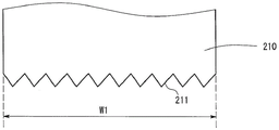
A cutting tool 210 as shown in fig. 6 may be used. A concave-convex portion 211 is formed at the distal end portion of the cutting tool 210. The concave-convex portion 211 is formed to extend in the direction of the width W1 of the cutting tool 210. Therefore, when the surface of the work piece WP1 is machined in one direction by using the cutting tool 210, a plurality of concave portions corresponding in number to the number of convex portions of the concave-convex portion 211 are formed on the surface of the work piece WP 1. Needless to say, the micromachining is performed on the surface of the work WP1 at the same time by the vibration of the vibration unit 120.
As shown in fig. 7, a cutting tool 310 having a very small flat surface 311 may be used. A very small flat surface 311 is formed at the distal end of the cutting tool 310. When such a cutting tool 310 is used, the microstructure having the bottom surface WP1c and the convex portion is transferred (transferred) to the surface of the work piece WP 1. During machining, planar surface 311 of cutting tool 310 presses against work piece WP1 at its contact area without removing work piece WP1 due to the creation of debris. Thus, the machining force acting on work piece WP1 increases slightly. However, since the width of the flat surface 311 of the cutting tool 310 is very small, a portion of the work piece WP1 in contact with the cutting tool 310 (the portion corresponding to the bottom surface WP1c) is plastically deformed without any problem.
5-3 machining of curved surfaces
In this embodiment, the surface of work piece WP1 is flat. However, even when work WP1 has a curved surface, minute concave portions and convex portions may be formed on the curved surface by micromachining. For example, the table 130 may be moved to trace a curved surface.
5-4. polishing
The micro-machining apparatus 100 of the present embodiment can perform the polishing process of removing the surface layer of the work WP1 while forming minute concave portions and convex portions on the surface of the work WP 1. Even when the work piece WP1 has a slightly rough surface due to cutting or grinding, the surface of the work piece WP1 can be polished to a mirror surface or an iridescent surface by using the machining method of the present embodiment.
5-5 in the first direction
In the present embodiment, when the first direction K1 is projected onto the x-y plane, the first direction K1 projected onto the x-y plane is parallel to the x-axis direction (average cutting direction J1). However, the first direction K1 projected onto the x-y plane may be inclined at a predetermined angle with respect to the x-axis direction. However, when the angle is 0 ° as in the present embodiment, a deeper concave-convex shape can be formed. In particular, when the angle is other than 0 °, the angle θ may be defined by using the first direction K1 projected onto the x-z plane.
5-6 in the width direction of the cutting edge
The present embodiment has been described under the following assumptions: when the direction of the cutting edge width of the cutting tool 110 is projected on the x-y plane, the direction of the cutting edge width of the cutting tool 110 projected on the x-y plane is parallel to the y-axis direction. However, the direction of the cutting edge width of the cutting tool 110 may be set to be not parallel to the y-axis direction. That is, when the direction of the cutting edge width of the cutting tool 110 is projected onto the x-y plane, the direction of the cutting edge width of the cutting tool 110 projected onto the x-y plane may form a predetermined angle γ with respect to the y-axis. In this case, the pitch of the grooves formed on the surface of work piece WP1 is represented by λ cos γ.
5-7 attachment of cutting tools
In fig. 1, the cutting tool 110 is attached to the vibration unit 120 at a predetermined angle. However, it is preferable that the angle of the cutting tool 110 with respect to the vibration unit 120 may be freely changed according to the shapes of the concave portion and the convex portion to be formed. Preferably, the micro-machining apparatus 100 has a connection portion that allows an operator to freely change an angle at which the cutting tool 110 is attached to the vibration unit 120. As the attachment angle of the cutting tool 110 changes, the rake angle changes.
5-8. other modifications
The above modifications can be freely combined.
6. Brief description of the embodiments
The micro-machining apparatus 100 of the present embodiment has a cutting tool 110 and a vibration unit 120. Since the vibration unit 120 oscillates periodically, the cutting tool 110 can perform micromachining on the surface of the work piece WP 1. In addition, as shown in expression (2), when the vibration unit 120 having a high vibration frequency is used, a sufficiently large cutting speed v can be set in relation to the pitch λ of the concave portion and the convex portion.
(second embodiment)
A second embodiment will be described. The workpiece of the second embodiment is a mold.
1. Method for manufacturing mold
1-1. Forming Process of mold parts
First, a mold part is formed. For this purpose, a machining apparatus such as a machining center or an ultra-precision machining apparatus may be used.
1-2. micro-machining Process
Next, micromachining is performed on the inner side of the mold member by using the micromachining apparatus 100. The specific conditions of the machining are the same as those already described in the first embodiment. That is, minute concave portions and convex portions are formed on the surface of the mold by using the vibrating cutting tool 110 under the machining conditions that have been described in the first embodiment.
1-3 other procedures
In addition, the following members may be used as the mold: the shapes of the concave portions and the convex portions formed by micromachining are transferred on the member by electroforming or a similar process. The heat treatment process or the like for heat treating the mold member may be performed as needed. In addition, a grinding process for grinding the mold part may be performed. In addition, other processes may be performed.
2. Modifications of the type
2-1. concave-convex shape of cutting tool
As shown in fig. 7, a cutting tool 310 having a flat surface 311 at a distal end portion of the cutting tool 310 may be used. In this case, a flat bottom surface WP1c is formed in each of the minute grooves of the mold. The bottom surface WP1c of the mold is used to form the convex portion by transfer on the product molded by using the mold. Since the bottom surface WP1c is formed on the mold, the top portion of the convex portion of the product is flat to some extent. Therefore, the surface of the product is less likely to be damaged. In addition, a cutting tool having a circular surface instead of the flat surface 311 may be used. In this case, the convex portion of the molded product has a rounded top portion. Therefore, the surface of the product is less likely to be damaged.
2-2. other modifications
The second embodiment and its modifications may be freely combined with the first embodiment and its modifications. Examples of the invention
1. Setting up of devices
An angle θ formed between the first direction K1 and the average cutting direction J1 was set to 45 °. The cutting tool 110 is a diamond cutter. The vibration frequency of the vibration unit 120 is 35kHz and the total amplitude is about 5 μm. The feed rate (cutting speed) was 1 m/min.
2. Other machining conditions
Work piece WP1 is formed from a copper alloy. The pitch is about 0.5 μm.
3. Results
FIG. 8 is a photomicrograph of the surface of work piece WP 1. As shown in fig. 8, periodic depressions and projections are formed on the surface of work piece WP 1.
FIG. 9 is a photograph showing the surface of work piece WP 1. As shown in FIG. 9, the surface has an iridescent luster when work piece WP1 is viewed from an appropriate angle. Alternatively, the surface of work piece WP1 may be a mirror-finished surface.
Description of reference numerals and symbols
100: micro-machining equipment
110: cutting tool
120: vibration unit
130: working table
WP 1: workpiece
Claims (3)
1. A method of micromachining comprising:
the following machining equipment was used: the machining apparatus includes a cutting tool and an ultrasonic vibration unit for vibrating the cutting tool in a first direction;
setting an angle formed between an average cutting direction of the cutting tool and the first direction to fall within a range of 20 ° to 120 °;
causing a concave portion and a convex portion to be formed on a surface of a workpiece due to machining by the cutting tool that is vibrating; and
allowing the average cutting speed of the cutting tool to satisfy the following expression:
v·cosα<2πaf·cos(θ+α)
λ=v/f
wherein the content of the first and second substances,
v represents the average cutting speed and v represents the average cutting speed,
a represents the half amplitude of the ultrasonic vibration,
f represents the frequency of the ultrasonic vibrations,
theta represents the angle formed between the average cutting direction of the cutting tool and the first direction,
a denotes a rake angle of the cutting tool as viewed in a plane including the average cutting direction and the first direction of the cutting tool, the sign of the rake angle being determined such that: the cutting edge of the cutting tool is sharp when the rake angle is positive and blunt when the rake angle is negative, and
λ represents a distance between the concave portion and the convex portion,
the average cutting direction is the direction in which the average position of the oscillating cutting tool with respect to the workpiece is moved,
the average position of the cutting tool that vibrates is the center of the amplitude of vibration of the cutting tool.
2. A method of manufacturing a mold, comprising:
the following machining equipment was used: the machining apparatus includes a cutting tool and an ultrasonic vibration unit for vibrating the cutting tool in a first direction;
setting an angle formed between an average cutting direction of the cutting tool and the first direction to fall within a range of 20 ° to 120 °;
causing recesses and protrusions to be formed on a surface of a die due to machining by the cutting tool being vibrated; and
allowing the average cutting speed of the cutting tool to satisfy the following expression:
v·cosα<2πaf·cos(θ+α)
λ=v/f
wherein the content of the first and second substances,
v represents the average cutting speed and v represents the average cutting speed,
a represents the half amplitude of the ultrasonic vibration,
f represents the frequency of the ultrasonic vibrations,
theta represents the angle formed between the average cutting direction of the cutting tool and the first direction,
a denotes a rake angle of the cutting tool as viewed in a plane including the average cutting direction and the first direction of the cutting tool, the sign of the rake angle being determined such that: the cutting edge of the cutting tool is sharp when the rake angle is positive and blunt when the rake angle is negative, and
λ represents a distance between the concave portion and the convex portion,
the average cutting direction is the direction in which the average position of the vibrating cutting tool with respect to the mold moves,
the average position of the cutting tool that vibrates is the center of the amplitude of vibration of the cutting tool.
3. A micro-machining apparatus comprising:
a cutting tool and an ultrasonic vibration unit for vibrating the cutting tool in a first direction;
an angle formed between an average cutting direction of the cutting tool and the first direction falls within a range of 20 ° to 120 °; and
the average cutting speed of the cutting tool satisfies the following expression:
v·cosα<2πaf·cos(θ+α)
λ=v/f
wherein the content of the first and second substances,
v represents the average cutting speed and v represents the average cutting speed,
a represents the half amplitude of the ultrasonic vibration,
f represents the frequency of the ultrasonic vibrations,
theta represents the angle formed between the average cutting direction of the cutting tool and the first direction,
a denotes a rake angle of the cutting tool as viewed in a plane including the average cutting direction and the first direction of the cutting tool, the sign of the rake angle being determined such that: the cutting edge of the cutting tool is sharp when the rake angle is positive and blunt when the rake angle is negative, and
λ represents a distance between a concave portion and a convex portion formed on the surface of the workpiece being machined due to machining by the cutting tool being vibrated,
the average cutting direction is the direction in which the average position of the oscillating cutting tool with respect to the workpiece is moved,
the average position of the cutting tool that vibrates is the center of the amplitude of vibration of the cutting tool.
Applications Claiming Priority (3)
| Application Number | Priority Date | Filing Date | Title |
|---|---|---|---|
| JP2016-113065 | 2016-06-06 | ||
| JP2016113065A JP6725917B2 (en) | 2016-06-06 | 2016-06-06 | Fine processing method, mold manufacturing method, and fine processing apparatus |
| PCT/JP2017/020509 WO2017213026A1 (en) | 2016-06-06 | 2017-06-01 | Micromachining method, die manufacturing method, and micromachining apparatus |
Publications (2)
| Publication Number | Publication Date |
|---|---|
| CN109311095A CN109311095A (en) | 2019-02-05 |
| CN109311095B true CN109311095B (en) | 2020-11-10 |
Family
ID=60577817
Family Applications (1)
| Application Number | Title | Priority Date | Filing Date |
|---|---|---|---|
| CN201780034679.8A Active CN109311095B (en) | 2016-06-06 | 2017-06-01 | Micro-machining method, mold manufacturing method, and micro-machining apparatus |
Country Status (5)
| Country | Link |
|---|---|
| US (1) | US20190299480A1 (en) |
| EP (1) | EP3466572A4 (en) |
| JP (1) | JP6725917B2 (en) |
| CN (1) | CN109311095B (en) |
| WO (1) | WO2017213026A1 (en) |
Families Citing this family (3)
| Publication number | Priority date | Publication date | Assignee | Title |
|---|---|---|---|---|
| CN108517477B (en) * | 2018-04-16 | 2020-10-23 | 中国兵器工业第五九研究所 | Deep conical copper liner tissue superfine grain gradient control method |
| JPWO2022269751A1 (en) * | 2021-06-22 | 2022-12-29 | ||
| CN114749992B (en) * | 2022-03-10 | 2023-06-06 | 清华大学 | Processing method and system for micro-texture groove with special-shaped cross section |
Family Cites Families (9)
| Publication number | Priority date | Publication date | Assignee | Title |
|---|---|---|---|---|
| JPS58143901A (en) * | 1982-02-18 | 1983-08-26 | Junichiro Kumabe | Turning and cutting method by fine and high speed oscillation |
| SE520088C2 (en) * | 2000-04-06 | 2003-05-20 | Skf Sverige Ab | Method for chip cutting machining of a workpiece |
| US7628099B2 (en) * | 2000-10-28 | 2009-12-08 | Purdue Research Foundation | Machining method to controllably produce chips with determinable shapes and sizes |
| JP3726091B2 (en) * | 2003-07-31 | 2005-12-14 | テクノダイイチ株式会社 | Cutting method and cutting apparatus for flat plate end face |
| JP4553967B2 (en) * | 2008-03-19 | 2010-09-29 | パナソニック株式会社 | Cutting apparatus, processing method, and mold processed by the processing method |
| CN101284315A (en) * | 2008-05-26 | 2008-10-15 | 刘沛恩 | Cutting process for improving the friction deformation between the chip and the front cutter face and cutter |
| WO2011029079A1 (en) * | 2009-09-05 | 2011-03-10 | M4 Sciences, Llc | Control systems and methods for machining operations |
| CN102049531B (en) * | 2010-11-04 | 2014-07-02 | 北京航空航天大学 | High-speed continuous ultrasonic radial vibration cutting method and realization device thereof |
| JP5464509B2 (en) * | 2011-12-19 | 2014-04-09 | コニカミノルタ株式会社 | Mold manufacturing method |
-
2016
- 2016-06-06 JP JP2016113065A patent/JP6725917B2/en active Active
-
2017
- 2017-06-01 EP EP17810204.2A patent/EP3466572A4/en active Pending
- 2017-06-01 US US16/307,688 patent/US20190299480A1/en not_active Abandoned
- 2017-06-01 CN CN201780034679.8A patent/CN109311095B/en active Active
- 2017-06-01 WO PCT/JP2017/020509 patent/WO2017213026A1/en unknown
Also Published As
| Publication number | Publication date |
|---|---|
| EP3466572A4 (en) | 2020-02-26 |
| JP6725917B2 (en) | 2020-07-22 |
| WO2017213026A1 (en) | 2017-12-14 |
| CN109311095A (en) | 2019-02-05 |
| EP3466572A1 (en) | 2019-04-10 |
| JP2017217720A (en) | 2017-12-14 |
| US20190299480A1 (en) | 2019-10-03 |
Similar Documents
| Publication | Publication Date | Title |
|---|---|---|
| CN109311095B (en) | Micro-machining method, mold manufacturing method, and micro-machining apparatus | |
| Xu et al. | Fabrication of hybrid micro/nano-textured surfaces using rotary ultrasonic machining with one-point diamond tool | |
| Aurich et al. | Abrasive processes for micro parts and structures | |
| CN104117697B (en) | A kind of off-resonance elliptical vibration cutting device | |
| JP2005527394A (en) | Diamond tool with multi-chip diamond | |
| Peng et al. | Effect of vibration on surface and tool wear in ultrasonic vibration-assisted scratching of brittle materials | |
| Liu et al. | Fabrication of micro-textured surface using feed-direction ultrasonic vibration-assisted turning | |
| JP3500434B2 (en) | Vibration cutting method and vibration cutting device | |
| JP2017217720A5 (en) | ||
| Kim et al. | Cutting force variation with respect to tilt angle of trajectory in elliptical vibration V-grooving | |
| JP6006959B2 (en) | Method for forming recess, corner corner finishing method and mold manufacturing method | |
| Xu et al. | Development of a novel 2D rotary ultrasonic texturing technique for fabricating tailored structures | |
| CN110090967A (en) | Great surface quality ultra precision cutting manufacturing process based on multi-freedom-degree vibration | |
| CN105458902B (en) | A kind of micro-structure surface three-dimensional elliptical vibrates Ultraprecise polished method | |
| JP4973827B2 (en) | Elliptical vibration cutting method | |
| US8122584B2 (en) | Method of producing honeycomb structure molding die | |
| CN103418848A (en) | Cutting technology with micromachining achieved with particulate knife | |
| Yan et al. | Machining slight burr formed micro-channels with different moving trajectories of a pyramidal diamond tip | |
| Lin et al. | Study on the tool wear of 3-D elliptical vibration cutting | |
| Hassan et al. | A review of the milling process to fabricate a dimple structure | |
| EP1382414B1 (en) | Method of making a cutting tool blade | |
| JP6793912B2 (en) | Vibration processing equipment and vibration processing method | |
| JPS58196934A (en) | Precision oscillation cutting method for ceramics | |
| JP2024025598A (en) | A device for cutting a workpiece in straight lines and arbitrary curves using a wire mesh grindstone of a micro-vibrating tool holder provided on the main axis of an NC-controlled machine tool, and a method for cutting straight lines and arbitrary curves using the wire mesh grindstone provided in the micro-vibrating tool holder. | |
| RU2221686C1 (en) | Method for working cylindrical parts |
Legal Events
| Date | Code | Title | Description |
|---|---|---|---|
| PB01 | Publication | ||
| PB01 | Publication | ||
| SE01 | Entry into force of request for substantive examination | ||
| SE01 | Entry into force of request for substantive examination | ||
| GR01 | Patent grant | ||
| GR01 | Patent grant |